EEE_30
GPS TRACKING SYSTEM FOR AIRSHIP
Ignatius Agung Wibowo, Darwin Sebayang and Chee Chia Loon
Faculty of Electrical and Electronics Engineering, Universiti Tun Hussein Onn, Johor, Malaysia Email: [email protected]
ABSTRACT
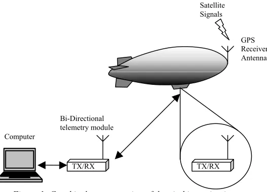
An airship is a lighter-than-air aircraft that can be controlled and propelled through the air. The airship has been widely used today whether for commercial purposes, experimental purposes, or individual leisure pursuit purpose. The factor of low cost and easy in fabrication made it a popular airmobile unit. A team in Universiti Tun Hussein Onn Malaysia (UTHM) has developed an airship with 8 meters length. The team is developing the structure, envelope, gondola, fins, powerplant, flight control, navigation, telemetry, and video monitoring systems of the airship. This paper presents the research on the development of the navigation system especially the tracking system for the airship. At the first stage of the development, the airship will be steered through a radio control. Since the airship can moves around freely in the air, it is appropriate for it to have a tracking system so that the position of the airship can be monitored or even recorded at anytime or anywhere. The prototype of a GPS based navigation system for the airship has been developed. The GPS receiver chosen is Lassen iQ by Trimble. A pair of RF circuits is included to provide wireless data transmission from the GPS receiver to the ground station. An interface circuit is created to connect the RF receiver to a computer. Software is also written to parse the GPS data so that relevant information can be extracted. A visual display of the position of the airship has also being implemented in the user interface software. The system has been successfully tested and able to provide and update position data continuously.
Keywords: airship, navigation, global positioning system, tracking.
INTRODUCTION
An airship is a buoyant ("lighter-than-air") aircraft that can be steered and propelled through the air. The popularity of the airship can be easily traced by various names given to it. It has been known as airship, blimp and lighter than-air craft (LTA). There are plenty of autonomous airship in various sizes that have been built by academic organizations, commercial organizations and personal individuals.
An airship with 8 meters length is being developed by a team in Universiti Tun Hussein Onn Malaysia (UTHM). The team is developing the structure, envelope, gondola, fins, powerplant, flight control, navigation, telemetry, and video monitoring systems of the airship. The airship is intended to be built as an unmanned autonomous vehicle for surveillance purposes therefore a appropriate navigation system which is able to track the position of the airship should be considered. This paper presents the design and development of the navigation system of the airship.
Several types of navigation system have been tried out by other airship builders. Those include INS-GPS, AHRS and some as simple as GPS tracking navigation. The high level navigation system such as INS-GPS and AHRS require considerable superior knowledge in aerospace engineering due to the complicated mathematical models applied such as the Kalman Filtering. In addition to that, the high orders mathematical models require excellent programming sequences that must be processed by a single-board computer.
Figure 1: Graphical representation of the airship navigation system
A literature review has been done in order to design and develop the navigation system of the airship. The literatures include GPS-GSM Mobile Navigator[1] and Autonomous GPS Controlled Vehicle[2].
GPS-GSM Mobile Navigator Project which was done by Ma and Lin combines the Global Positioning System (GPS) and the Global System for Mobile Communication (GSM) for the purpose of ships tracking at ports[1]. The system equipped all ships with a mobile unit that communicates with a base station. The mobile navigator is based on a microcontroller that manipulates the GPS receiver and a GSM module operating in 900MHz band. The microcontroller used is a low power CMOS 8-bit microcontroller by Atmel Corporation. It serves at the processing unit of the system as well as the controller of the system. The microcontroller receives data from GPS receiver and processes them to make decision whether to send the data to base station (user defined or by requirements) or stored in on-board flash memories (every 20 seconds).
The GPS data is formatted into a standard fixed-length packet (42 byte data package) with some useful information by the microcontroller to be stored into the flash memory or transmitted to the base station. The GPS receiver used is Sandpiper OEM GPS module from Axiom that supports DGPS. DGPS is not utilized in this project causing poor accuracy in about 25m.
The communication between the mobile navigator and the base station is based on GSM900 network. The position and other important information are sent to the base station via SMS at user defined time interval. AT commands is used to send the SMS in GSM 07.07 protocol. A stand alone GSM OEM module, FALCOMA2D from Wavecom is used.
In Autonomous GPS Controlled Vehicle Project developed by Rudy Manzano and Kelly Matsumo[2] a device that will move to a specified waypoint guided by a GPS receiver was built. The project is broken into several parts including GPS module, Microcontroller module, C Code module and Remote Control Car module.
The GPS receiver provides a lot of information to user in several protocols. The most widely used protocol is the NMEA (National Marine Electronics Association) protocol. There are also many standards in this protocol itself. Only two of the standards are used in this project. The two standards are the RMC and RMB. These two sentences will give the instantaneous position, range and true bearing to the destination. The data that is used to determine the range and true bearing to destination are illustrated in Figure 2 in bold.
RMC - Recommended minimum specific GPS/Transit data
$GPRMC,225446,A,4916.45,N,12311.12,W,000.5,054.7,191194,020.3,E*68
RMB - Recommended minimum navigation information Computer
Bi-Directional telemetry module
GPS Receiver Antenna
TX/RX TX/RX
The GPS module will interact with the microcontroller via the serial port that is compatible with RS232 signal levels. The serial ports are also used as terminals to transfer files to or from computer.
The I/O ports that are used are port 1 and port 3 that can carry 8 bits of data each. The special function registers at in the microcontroller is used to manipulate the port pins that will control the Remote Controlled Car Module.
MATERIALS AND METHODS
The development the airship navigation system is divided into 2 phases, i.e.: Phase 1: Development of tracking sub-system
Phase 2: Development of auto-cruise sub-system
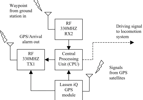
[image:3.595.148.434.242.442.2]The hardware configuration of the system is shown in Figure 3 and Figure 4.
Figure 3: On-vehicle Navigation Hardware block diagram
Figure 4: Ground Station Block Diagram
For easy interfacing purpose, NMEA protocol is used for communication between the GPS receiver,
microcontroller and to the computer. The GPS data is transmitted and received in 8 bit packet in ASCII strings and comma separated fields as illustrated in Figure 5.
RF 330MHz
RX1
Ground Station Computer RS232/TTL
Driver RF
330MHz TX2
RS232/TTL Driver Waypoint
to CPU out
GPS/Arrival alarm in
Central Processing Unit (CPU)
RF 330MHZ
RX2
Lassen iQ GPS module Waypoint
from ground station in
Signals from GPS satellites
Driving signal to locomotion system
RF 330MHZ
TX1 GPS/Arrival
[image:3.595.162.441.475.631.2]Figure 5: NMEA protocol
RESULTS AND DISCUSSIONS
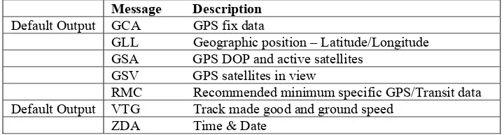
[image:4.595.115.475.327.424.2]The Lassen iQ receiver has 2 I/O ports and is capable of sourcing 3 types of output protocols. They are NMEA, TAIP and TSIP. But, only NMEA protocol is used for this project. The NMEA protocol does provides a wide range of data sentences, but the Lassen iQ only supports some of them. The sentences supported are listed in Table 1 below.
Table 1: Lassen iQ NMEA sentences
Message Description
Default Output GCA GPS fix data
GLL Geographic position – Latitude/Longitude GSA GPS DOP and active satellites
GSV GPS satellites in view
RMC Recommended minimum specific GPS/Transit data Default Output VTG Track made good and ground speed
ZDA Time & Date
The NMEA protocol has standard configuration of 4800 baud rate, 8 bits data bits, no parity and one stop bit. The configuration of the NMEA protocol of Lassen iQ are not limited to the previous configuration as it can be modified to suit the user demand. The manufacturer provided 2 types of interface software for Lassen iQ that is iQ_Chat (DOS application) and iQ_Monitor (Windows application). The data output rate could also being adjusted in the range of 1 second to 20 seconds with 1 second scale. The NMEA sentences are output in ASCII standard so that it can be view with common computer application such as Hyper Terminal.
[image:4.595.143.459.604.679.2]Due to the low baud rate of the RF330MHz wireless link which is capable of operating to the maximum baud rate of 2400 baud, the Lassen iQ has been configured to the baud rate of 2400 baud by using iQ_Chat. RMC and GSV sentences also had been configure to on as factory settings does not display them. During an experiment to operate NMEA data with lower baud rate, some sentences are being discarded. This test is done without the wireless link that limits the baud rate. The settings on the baud rate of Lassen iQ and hyper terminal must also being synchronize. The test result is shown in Table 2 below.
Table 2: Transmitting with different baud rate
Baud Rate Number of character supported every second (1 ASCII char = 8
bit)
Sentence Discarded
2400 300 RMC 4800 600 None 9600 1200 None $GPRMC,161229.487,A,3723.2475,N,12158.3146,W,0.13,309.62,120598,,*10.
Start
Talker Identification
Figure 6: Lassen iQ output data viewed with Hyper Terminal (Notice the V flag in the RMC sentence that indicate invalid data)
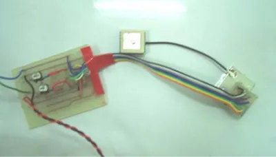
[image:5.595.197.397.340.454.2]A simple evaluation circuit board has also being made to provide power to the Lassen iQ unit as shown in Figure 7. The circuit board also serves as electrical configuration to the Lassen iQ so that it could function properly. The electrical configurations made are with accordance to the Lassen iQ User Manual provided by the manufacturer.
Figure 7: Lassen iQ attached to evaluation board
The ouput of the Lassen iQ is TTL compatible level (0V for 0 logic and 5V for 1 logic). Therefore, a computer interface board is used to convert the voltage level to RS232 protocol level that is understandable by computer. In the interface board, an RS232 driver from Texas Instrument is used. After the GPS is connected to the evaluation board and computer interfacing board, Hyper Terminal is used to view the output of the data of Lassen iQ.
Information extracted from the Lassen iQ will only contain relevant information if the unit is functioning in wide open space. The reason is the Lassen iQ need to track at least four different satellites so that it can calculate its position on earth. The Lassen iQ could support up to 12 satellites at any moment. The more satellites it can reach, the greater the accuracy will be.
A test had been done to verify the accuracy of GPS system using a Garmin© e-Trex Summit Personal Navigator. At a open area, such as the campus car park, the accuracy displayed is around 9m while between building, the accuracy greatly decreases to 49m.
A set of low end RF wireless link is used to transmitting the data wirelessly from Lassen iQ to computer. The RF 330MHz module operates at a maximum baud rate of 2400 baud and has as operating range of 100m. It is capable of transmitting digital data without any extra circuitry or configuration. However, a PCB is fabricated for shield grounding purpose to reduce interference during transmission.
The data is transferred 1 byte at a time which represents an ASCII character. The NMEA protocol sentence start with a talker ID, followed by the message ID, data fields and end with carriage return [CR] and line feed [LF] combination.
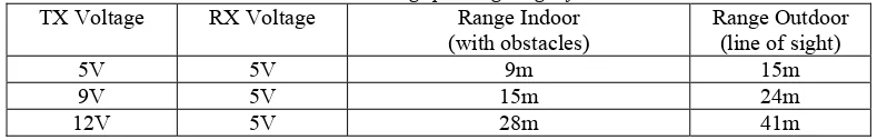
[image:6.595.96.495.196.259.2]A range test had also being conducted and proved that the true practical range for the RF module to operate is only around 20m by using a common omni directional radio antenna in line of sight. By doing some study on the internet, the operating range of the RF module is said can be significantly increase by using a proper antenna for the module. The recommended antenna that can be used is an 8.9 inches 434MHz omni directional whip antenna. Table 3 shows the result of the test.
Table 3: Result in testing operating range of RF 330MHz
TX Voltage RX Voltage Range Indoor
(with obstacles) Range Outdoor (line of sight)
5V 5V 9m 15m
9V 5V 15m 24m
12V 5V 28m 41m
From the result, it is known that the obstacle greatly decreases the transmission of the data because it is blocked by walls. Besides, the voltage supply to the transmitter could cause a big difference to the range performance of the module. The transmitter is capable of operating in the voltage range of 5V to 12V. The greater the voltage, the greater the transmitted signal is. Weak battery could also caused distortion in data received. Therefore, the power supply to the RF module should always being checked to avoid transmission failure.
Due to simplicity and low price of this module, its capability is limited. Two pairs of the module have been bought to be implemented to the system. Somehow, only one set is allowed to operate at one time because of it is single channel and operating at the same frequency. Another disadvantage of this module is when the range between the transmitter and receiver changed drastically, the transmission is interrupted or paused.
As a recommendation, a high frequency wireless link such as 2.4GHz can be used to achieve greater distance and minimize interference. An AeroComm 2.4GHz transceiver even incorporated FSK modulation to help decrease the possibilities of lost of data due to interference. It also capable of operating to more than 9600 baud that is needed to preserve the data output from Lassen iQ.
[image:6.595.79.526.505.667.2]For the convenience of user, the GPS data has to be extracted to display only relevant or desired field of data. In the NMEA data protocol, each sentence may have only one or two desired field of data that is desired to be displayed. Table 4 displays the data field that will be extracted with reference to the NMEA sentence.
Table 4: NMEA sentences with data field parsed
Sentence Data Extracted Field Extracted
$GPGGA Fix data $GPGGA,123519,4807.038,N,01131.324,E,1,08,0.9,545.4,M,46.9,M, , *42
$GPGGL Position $GPGLL,4916.45,N,12311.12,W,225444,A
$GPGSA Active satellites $GPGSA,A,3,04,05,,09,12,,,24,,,,,2.5,1.3,2.1*39
$GPGSV
Satellites in
view $GPGSV,2,1,08,01,40,083,46,02,17,308,41,12,07,344,39,14,22,228,45*75
$GPRMC Position and time $GPRMC,225446,A,4916.45,N,12311.12,W,000.5,054.7,191194,020.3,E*68
receive action. Meanwhile the event driven method will receive data at anytime data is detected in the receive buffer.
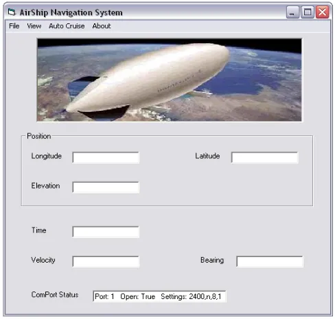
Figure 8: Main window of Airship Navigation User interface
The auto cruising is built up of the connection between the Lassen iQ, a microcontroller (PIC16F877), and a computer. This system requires user to input waypoints via the user interface. Next, the waypoint will be transmitted to the microcontroller using a RF wireless module. The waypoint data will then be extracted by the microcontroller. Then the microcontroller will receive real time GPS data and compare it with the waypoint to select appropriate signal to the locomotion system.
The waypoint data will be inserted by user via the user interface. A protocol is needed in order for the microcontroller to extract, store and compare the data. To avoid confusion between the NMEA sentences and waypoint sentence, a special talker ID is assigned to the waypoint data. The prefix capital “WP” is used.
There are only two fields assigned to the waypoint data. They are the desired longitude and desired latitude. Figure 9 is an example of waypoint data with some explanation of the data fields.
WP Special waypoint talker ID
0151.59,N Latitude 01 degree 51.59 minute North 10305.29,E Longitude 103 degree 05.29 minute West
Figure 9: Waypoint data
A window as shown in Figure 10 has also been included in the user interface software to allow user to input waypoint data. It also serves as the monitor of the auto-cruising process. It has three status indicators indicating Ready (ready to receive waypoint), In Progress (auto-cruising in progress) and Destination Arrived (desired destination achieved).
Figure 10: The Auto-Cruise window
A firmware has been written for the PIC. Firstly it parses the waypoint and GPS real time data and store in buffer and later being compared. The result determines the output of the signal that maneuvers the airship autonomously. A Microchip© PIC16F877 is selected to do the task. To receive both the GPS and the waypoint data, a multiplexer is used. This is because there is only one serial communication port available on PIC16F877. The firmware is written to select multiplexer to receive waypoint data first and followed by GPS data.
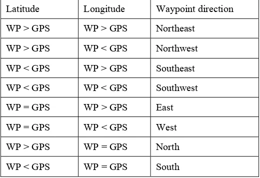
Due to unavailability of RMB sentence in Lassen iQ GPS receiver an alternative method was selected to compare the waypoint latitude and longitude to the instantaneous GPS latitude and longitude. Table 5 illustrates how the comparison works.
Table 5: Determine the direction of waypoint with reference to airship
Latitude Longitude Waypoint direction
WP > GPS WP > GPS Northeast
WP > GPS WP < GPS Northwest
WP < GPS WP > GPS Southeast
WP < GPS WP < GPS Southwest
WP = GPS WP > GPS East
WP = GPS WP < GPS West
WP > GPS WP = GPS North
WP < GPS WP = GPS South
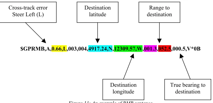
[image:8.595.168.428.378.556.2]Figure 11: An example of RMB sentence
A system board is fabricated to house the microcontroller and provide ports to the GPS receiver and RF link to receive waypoint data. The microcontroller also has six of its parallel I/O configured to send driving signals to locomotion board.
CONCLUSIONS
As the conclusion, the navigation system for position tracking of the UTHM airship using GPS has been successfully designed and developed. The system is ready to be installed to the airship for completing the auto cruise feature of the airship.
REFERENCES
[1] Ma, C. and Lin, M. (2003) GPS-GSM Mobile Navigator.” Feature Article of Circuit Cellar. Issue 151. 1-6. [2] Manzano, R. and Matsumo, K. (Undated) Autonomous GPS Controlled Vehicle Documentation,
http://www-ee.eng.hawaii.edu/%7Emanzano/
[3] Bennett, P. (2003) The NMEA FAQ, http://www.vancouver-webpages.com/peter/nmeafaq.txt
[4] Team Blimpyk (2002) Midterm Project Report: Blimpyk Wireless Sensor Module,
www.ece.osu.edu/ie/main/DesignProjects/Blimpyk/midterm_semi_final.doc
[5] Buschmann, M., Bange, J. and Vörsmann, P. (Undated) MMAV - A Miniature Unmanned Aerial Vehicle (Mini-UAV) For Meteorological Purposes, Technische Universität Braunschweig, Germany
[6] Trimble Navigation Limited (2005) Lassen iQ GPS Receiver: System Designer Reference Manual. [7] Bharat, S. (Undated) A Beginners Tutorial on GPS Serial Communications using Visual Basic, Drexel
University.
[8] Person, J. (Undated) How to Write a GPS Application, http://www.developerfusion.co.uk/show/4634/1/
[9] Farrell, J.A. and Matthew Barth, M. (1999) The global positioning system and inertial navigation, McGraw-Hill, New York.
[10] Grewal, M.S., Weill, L.R., and Andrews, A.P. (2001) Global positioning systems, inertial navigation, and integration, John Wiley, New York.
$GPRMB,A,0.66,L,003,004,4917.24,N,12309.57,W,001.3,052.5,000.5,V*0B
Cross-track error Steer Left (L)
Destination latitude
Destination longitude
Range to destination