CONTROLLER
MOHD EZWAN BIN MAHADAN
A project report submitted in partial fulfillment of the requirement for the award of the degree
Master of Electrical Engineering
Faculty of Electrical and Electronic Engineering University Tun Hussein Onn Malaysia
vi
ABSTRACT
This project presents the employment of a single-phase active power filter (APF) to compensate harmonics generated by battery charger. The presence of the harmonics leads to various problems and poor power quality. The objectives of this project are to reduce the harmonic distortion and improve the power factor of the single-phase system with battery charger load. The operation of APF is verified using the simulations in Matlab/Simulink. Artificial neural network (ANN) control based shunt APF is compared to proportional-integral (PI) controller in order to regulate the DC-bus voltage and hysteresis current controller is employed to generate signal for switching purpose. The process is based on sensing line voltages, line currents, filter currents and DC side capacitor voltage. The error signal caused by the filter has been computed firstly. Then this error signal has been compensated using the controller and generates reference line current. The reference filter currents signal then obtained by subtracts the reference line current with the load current. This reference filter current is feed to the hysteresis current controller and compare with the sensed filter currents to obtain the switching signal for active power filter. Simulation results show that the ANN controller based shunt APF has better performance which has reduced harmonic distortion and improve system performance compared to the use of conventional PI controller.
ABSTRAK
viii
CONTENTS
TITLE i
DECLARATION iii
DEDICATION iv
ACKNOLEDGEMENT v
ABSTRACT vi
ABSTRAK vii
TABLE OF CONTENTS viii
LIST OF FIGURES xi
LIST OF TABLES xiii
CHAPTER 1 INTRODUCTION
1.1 Overview 1
1.2 Problem Statement 3
1.3 Objectives of the project 3
1.4 Scope 4
1.5 Thesis outline 4
1.6 Related work 5
CHAPTER 2 LITERATURE REVIEW
2.1 Introduction 6
2.2 Active filter 7
2.3 Classifications of active power filter 7
2.4 Connection of active power filter 8
2.4.1 Shunt active power filter 8
2.4.2 Series active power filter 9
2.5 Reference signal estimation 10
2.5.1 Frequncy domain 11
2.6 Current control technique 12
2.6.1 Linear control 12
2.6.2 Hysteresis control 13
2.7 DC voltage regulation 14
2.7.1 PI controller 15
2.7.2 ANN controller 15
2.8 Research comparison 16
CHAPTER 3 METHODOLOGY
3.1 System Architecture 18
3.2 Reference compensations current 20
3.3 Control scheme 21
3.3.1 Voltage controller 22
3.3.1.1 PI controller 22
3.3.1.2 ANN controller 23
3.3.2 Hysteresis current controller 26
3.4 Inverter circuits 28
3.5 DC-bus capacitor 29
3.6 Interfacing inductor 29
CHAPTER 4 RESULT AND ANALYSIS
4.1 System modelling 31
4.2 System simulation without APF 32
4.3 System simulation with APF 34
4.3.1 APF based PI controller 35
4.3.2 APF based ANN controller 38
4.4 Performance comparison 41
4.5 Hysteresis current controller 42
CHAPTER 5 CONCLUSION
5.1 Conclusion 44
5.2 Recommendations 45
REFERENCES 46
PUBLICATION 50
VITA 51
APPENDIX A: Power factor calculation 52
x
APPENDIX C: ANN controller coding 58
LIST OF FIGURES
2.1 Configuration of a VSI based shunt APF 8
2.2 Configuration of a VSI based series APF 9
2.3 Operation principle of series APF 10
2.4 Linear control technique 12
2.5 Gating signal for linear control 13
2.6 Hysteresis control technique 14
2.7 Gating signal generation 14
3.1 Flowchart of project activities 18
3.2 System configuration 19
3.3 System architechture 19
3.4 Control scheme of APF 21
3.5 PI control algorithm 23
3.6 Proposed control algorithm 24
3.7 Hysteresis control technique 26
3.8 Hysteresis current control operation waveform 27
3.9 Voltage source inverter circuit 28
3.10 Switching ripple of the compensation current 30
4.1 Single-phase system without shunt APF 32
4.2 Voltage source and current source without shunt APF 33 4.3 THD analysis of the load current without shunt APF 33
4.4 Simulation model of shunt APF 34
4.5 Voltage source and current source with shunt APF
xii
4.6 THD analysis of the load current without shunt APF
based PI controller 35
4.7 DC bus voltage with PI controller 36
4.8 Reference current (IF*) and compensation current (IF)
of APF based PI 37
4.9 Source current and load current after compensation 37 4.10 Voltage source and current source with shunt APF
based ANN controller 38
4.11 THD analysis of the load current with shunt APF
based ANN controller 39
4.12 DC bus voltage with ANN controller 39
4.13 Reference current (IF*) and compensation current (IF)
of APF based ANN 40
4.14 Source current and load current after compensation 41
LIST OF TABLES
2.1 Comparison between each research 16
4.1 Circuit parameters of system 32
CHAPTER 1
INTRODUCTION
This chapter will focus on the brief introduction of the project to be carried out. The important overview or description including the problem statement, project objectives, and project scopes are well emphasized in this part.
1.1 Overview
In recent years, the wide use of electronic devices such as personnel computer, smart phones, tablet, and even electric vehicle leads to employment of battery chargers. Battery charger is a device used to put energy into a battery by forcing current through it. In general, it consists of at least a diode to convert AC source to DC source. Diode is a non-linear device which generates harmonic in the power system line. The presence of harmonics in the system leads to various problems and poor power quality. These harmonics cause an increase in level of rms supply current, which results an increase of power loss, heating of equipment, voltage sags, power factor reduction and also deteriorates the quality of power [1]. The application of passive filter to overcome this problem causes a few problems such as it is large in size and has fixed compensation characteristics and they may fall in series resonance with the source impedance so that voltage distortion produces excessive harmonic currents flowing into the passive filter [1].
connected. Series connected APF can be connect before the load in series with the mains using a matching transformer to eliminate the voltage harmonics and to balance and regulate the terminal voltage of the load. Also it can be used to regulate the negative sequence voltage at the load. So the series APF works as a controllable voltage source. The drawbacks of this series connected APF is, it only compensates the voltage harmonics and another problem is for the short circuit in the load end. This short circuit current passes through the series transformer winding, which may overload the series transformer [1].
For this project, Shunt APF is employing to the system. Generally shunt APF is designed to eliminate the majority of the harmonic current orders and thus prevent significant harmonic voltages. As is defined in IEEE 519-1992, harmonic voltage is created when harmonic current travels through the impedance of the electrical system toward the lowest impedance point [2]. Thus the APF in shunt connected uses power electronic device to produce current with 180 degree phase shift to the harmonic current to eliminate the harmonic current. The shunt APF act as another source which generates harmonic current with the same magnitude but opposite in direction to the system.
3
1.2 Problem statement
Nowadays, AC power supply is used as a main supply for operation system. Therefore it will become a problem if the AC supply is not in its original condition due to the harmonic generated by the load especially a device which attached with the power electronic circuits. This harmonic will lead to the power quality problem which reduces the value of power factor. To solve this problem, harmonic filter is needed in order to remove them from the supply systems.
1.3 Objectives of the project
The main objective in this project is to compare the system response with shunt APF based PI controller and the system with shunt APF based ANN controller in order to reduce harmonic distortions and to improve power factor as well for the system with battery charger load. Therefore by using shunt APF topology the low supply harmonic current will be reduced and thus, power factor will be improved on the supply side as well. This project also aims to control and regulate the DC bus voltage of the single-phase APF and to obtain the switching signal for the APF to generate appropriate current compensations. Other objectives of this project
are:-i. To develop a single-phase system with a battery charger load using Matlab/Simulink software.
ii. To develop a shunt APF based PI controller and implemented in Matlab/Simulink software.
iii. To develop a shunt APF based ANN controller and implemented in Matlab/Simulink software.
1.4 Scope
The scope of this project is to study the characteristic and effect of the harmonics on non-linear load which is battery charger and to evaluate performance of the shunt APF based PI controller and the system with shunt APF based ANN controller in order to suppress the harmonics in the supply side through the simulation. In other words the aim of APF is to produce the harmonics current with the same magnitude but opposite in phase from the load. The simulation of this project is base on single-phase system. Other scopes of this project are:
i. Use sine multiplication method for APF to extract reference supply current. ii. The switching control strategy is hysteresis current controller based on PWM
signals.
iii. The inverter system based on voltage source. iv. Shunt configurations of APF to the system.
v. Using Matlab/Simulink software for system development.
1.5 Thesis outline
The thesis is organized into 5 chapters which are introduction, literature reviews, methodology, simulations and results analysis, conclusion and recommendation.
Chapter I discuss the background and general idea of the proposed project. Besides that, the objective and scope of the project are stated in this chapter.
Chapter II discuss the reviews of the literature which includes the principles of technique implemented in the active harmonic filters. The brief reviews of the control strategy used in the proposed filters also mentioned in this chapter.
5
Chapter IV presents the simulation results and analyse the compensation performance of the proposed filter subject to a battery charger load. The simulation results of the systems performance have been observed.
LITERATURE REVIEW
Literature review has been conducted prior to undertaking this project to obtain the information of the technology available and the method that used by other researchers on the same topic. This chapter provides the summary of literature reviews on key topics related to the active power filter.
2.1 Introduction
7
2.2 Active filter
This chapter reviews the development of APF technologies. The advantage of the active filtering process over the passive filter is a factor of many researches to be performed on active power filters for power conditioning and their practical applications [9]. By implementing the APF for power conditioning, it provides functions such as reactive power compensations, harmonic compensations, harmonic isolation, harmonic damping, harmonic termination, negative-sequence current or voltage compensation and voltage regulation [10]. The main purpose of the APF installation by individual consumers is to compensate current harmonics or current imbalance as well as power factor improvements of their own harmonic-producing loads. Besides that, the purpose of the APF installation by the utilities is to compensate for voltage harmonics, voltage imbalance or provide harmonic damping factor to the power distribution systems [10].
The basic principle of APF is to produce specific currents components that cancel the harmonic components draw by the non linear load. The APF act as a harmonic source which is same in magnitude but opposite in direction to the harmonic caused by the non linear load. Reactive power required by the load also provided by APF and thus improve the power factor of the system. APF consists of an inverter with switching control circuit. The inverter of the APF will generate the desired compensating harmonics based on the switching gates provided by the controller. The crucial parts of this APF are to design the suitable controller and the filters configuration.
2.3 Classifications of active power filter
The most dominant type of active filter is the voltage source inverter-type active filter, which has been designed, improved, and used for many years and is now in the commercial stage [11,12]. Their losses are less than current source active filter and they can be used in multilevel and multistep configurations [11]. It consists of a DC-bus capacitor as energy storage and power electronic switches to generate harmonics currents according to the signal from controller.
2.4 Connections of active power filter
Active harmonic filter can be connected in several power circuit configurations. In general, they are divided into three main groups which are shunt APF, series APF and hybrid APF.
2.4.1 Shunt active power filter
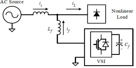
[image:17.612.209.437.518.632.2]This connection is most widely used in active filtering applications [3]-[5], [12]. It consists of a voltage or current source configurations. The voltage source inverter (VSI) based shunt APF is the most common type used today due to its well known topology and straight forward installation procedure [11]-[12].
Figure 2.1: Configuration of a VSI based shunt APF
9
harmonic currents due to nonlinear loads. The operation of shunt APF is based on injection of compensation current which is equals to the distorted current, thus eliminating the original distorted current. This is achieved by generates the compensation current waveform (i
f), using the VSI switches. The shape of compensation current is obtained by measuring the load current (i
L) and subtracting it from a sinusoidal reference. The aim of shunt APF is to obtain a sinusoidal source current (i
s) using the relationship: is=iL- if
2.4.2 Series active power filter
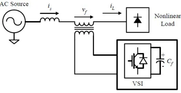
[image:18.612.187.496.391.550.2]The series APF is shown in Figure 2.2. It is connected in series with the distribution line through a matching transformer [13], [14]. VSI is used as the controlled source, thus the principle configuration of series APF is similar to shunt APF, except that the interfacing inductor of shunt APF is replaced with the interfacing transformer.
Figure 2.2: Configuration of a VSI based series APF
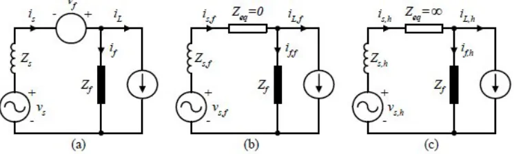
The operation principle of series APF is based on isolation of the harmonics in between the nonlinear load and the source. This is obtained by the injection of harmonic voltages (v
way that it presents zero impedance for the fundamental component, but appears as a resistor with high impedance for harmonic frequencies components. That is, no current harmonics can flow from nonlinear load to source, and vice versa.
Figure 2.3: Operation principle of series APF: (a) single-phase equivalent of series APF, (b) fundamental equivalent circuit, and (c) harmonic equivalent circuit
Series APFs are less common than the shunt APF. This is because they have to handle high load currents. The resulting high capacity of load currents will increase their current rating compared with shunt APF, especially in the secondary side of the interfacing transformer. This will increase the I2R losses [15]. However, the main advantage of series APFs over shunt is that they are ideal for voltage harmonics elimination. It provides the load with a pure sinusoidal waveform, which is important for voltage sensitive devices. With this feature, series APF is suitable for improving the quality of the distribution source voltage [12].
2.5 Reference signal estimations
11
voltage of the APF. Typical current variables are load current, AC source current and compensation current of the APF. Based on these system variables feedbacks, reference signals estimation in terms of voltage/current levels are estimated in frequency-domain or time-domain for example [3]-[5], [12],[15] report on the theories related to detection and measurement of the various system variables for reference signals estimation. These reference signal estimation techniques can divided into two groups which are frequency-domain and time-domain.
2.5.1 Frequency domain
Reference signal estimation in frequency-domain is suitable for single-phase system. They mainly derived from the principle of Fourier analysis which Fast Fourier Transform (FFT) is applied to the captured voltage or current signal. The main drawback of this technique is the accompanying time delay in system variables sampling and computation of Fourier coefficients. This makes it impractical for real-time application with dynamically varying loads. Therefore, this technique is only suitable for slowly varying load conditions [12].
2.5.2 Time domain
Time-domain approaches are based on instantaneous estimation of reference signal in the form of either voltage or current signal from distorted and harmonic-polluted voltage and current signals. These techniques include instantaneous p–q theorem, extension p-q theorem, synchronous d–q reference frame method, synchronous detection method and sine multiplication method [12], [16]. However, synchronous d–q reference frame method and synchronous detection method are only suitable for three-phase system [17]-[19] while instantaneous p–q theorem need some modifications in order to make it applicable for single-phase system [20]
integrating the result to calculate the real fundamental component of nonlinear load current [23]-[25]. The difference between the nonlinear load current and this fundamental component is the command current for the APF.
2.6 Current control techniques
The aim of APF is to generate appropriate harmonic currents compensations. This can be achieved by generate appropriate gating signal for APF’s inverter. The gating signal is based on the estimated compensation reference signals. The performance of an APF is affected significantly by the selection of control techniques [26]. A variety of control techniques, such as linear control, digital deadbeat control, hysteresis control etc., are implemented for the APF applications.
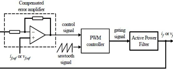
[image:21.612.182.514.409.544.2]2.6.1 Linear control
Figure 2.4: Linear control technique
13
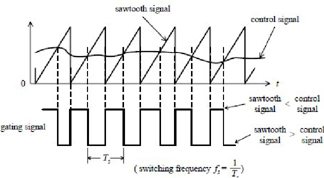
[image:22.612.177.501.132.310.2]transistors [21]-[25], [27]. The switching frequency is kept constant in linear control technique [12].
Figure 2.5: Gating signal for linear control
As shown in Figure 2.5, the gating signal is set high when the control signal has a higher numerical value than the sawtooth signal and low when the control signal has a lower numerical value than the sawtooth signal..
2.6.2 Hysteresis control
Figure 2.6: Hysteresis control technique
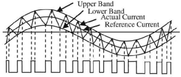
The APF is therefore switched in such a way that the peak-to-peak compensation current/voltage signal is limited to a specified band determined by upper band and lower band as illustrated by Figure 2.7. To obtain a compensation current with switching ripples as small as possible, the value of upper band and lower band can be reduced. However, doing so results in high switching frequency. Thus, increases losses on the switching transistors [12], [28].
Figure 2.7: Gating signal generation
2.7 DC voltage regulation
[image:23.612.175.480.381.511.2]15
power demand of the load decreases. Hence, by monitoring the capacitor voltage, the real power supplied by the APF can be estimated and the amplitude of the fundamental active component of the supply current was estimated indirectly [29].
2.7.1 PI controller
Classically, PI controller has been used widely for shunt APF. The PI controller scheme involves regulation of the DC bus capacitor voltage to set the amplitude of reference current for harmonic and reactive power compensation [29]. However, PI controller approach requires precise linear mathematical model which is difficult to obtain. It is also fails to perform satisfactory under parameter variations, non-linearity and load disturbances [15].
2.7.2 ANN controller
2.8 Research comparison
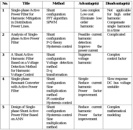
[image:25.612.126.554.225.646.2]The comparison for each of the previous studies regarding the APF is summarized in Table 2.1.
Table 2.1: Comparison of each research
No. Title Method Advantage(s) Disadvantage(s)
1 Single-phase Active Power Filter for Harmonic Mitigation in Distribution Power Lines.
Shunt configuration FFT algorithm SPWM
Less complex Low cost Eliminate low
order harmonic
Not applicable for high order harmonic
Compensate single harmonic in a time
2 Analysis of Single-phase Active Power Filter
Shunt configuration P-Q theory Hysteresis control
Feasible current harmonic detection
Improve the power current
Complicated
3 A Shunt Active Harmonic Filter Based on a Voltage Detection Method for Harmonic Voltage Control
Shunt configuration Voltage detection
method D-q transformation Suppress voltage harmonic Complex control factor 4 Single-phase Resonant Converter with Active Power Filter Shunt configuration Sine multiplication method PI controller Hysteresis control
Simple
Reduce current harmonic
Power factor improvement
Slow response DC bus voltage
unstable
5 Design of Single-phase Shunt Active Power Filter Based on ANN
Shunt configuration Hysteresis control Sine
multiplication method
Reduce current harmonic
Power factor improvement
CHAPTER 3
METHODOLOGY
This chapter will describe the method that will be used for this project in order to achieve the desire objectives. This project development is divided into two parts. The first part represented the development of system based on the PI controller and the second part will reflect to development of system that used ANN controller. Figure 3.1 compressed the project development.
The project developments shown in Figure 3.1 begin by the development of the single-phase system which consists of source and load. Extensive literature reviews were done on related knowledge to assist in any ways that it may. Such reviews are based on international publications, websites, and engineering books. The system requirement for the active power filter was then determined to proceed on this project.
Figure 3.1: Flowchart of project activities.
3.1 System architecture
19
IF
Is
I
LAPF
the load. The shunt APF also maintain the source signal in its original sinusoidal form by providing the reactive power required by the load, thus the source supply only active power to the system.
[image:28.612.133.505.153.328.2]Load
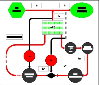
Figure 3.2: System configuration.
[image:28.612.161.496.383.666.2]Figure 3.3 shows the system architecture of this project which the APF is mounted in parallel to the system. The proposed topology is presented in the following sections. It will primarily focus on the operation principle, system configuration and overall control system design. The system configuration and design that was based on pulse-width modulated (PWM) voltage source inverter (VSI). The filter was shunt-connected with the load that being compensated. The figure 3.2 also shows the concept of the harmonic current cancellation so that the current being supplied from the source was sinusoidal. Upon the voltage controller receive the error signal, the source voltage is extracted to generate unity sinusoidal signal to multiply with the peak DC signal from the voltage controller. The output of this operation will generate reference source current, IS*. At this point, the reference source current is removed from the detected load current, ILto extract reference filter current, IF*. This allows the proposed active power filter to produce the output current, IF according to the reference current IF*. These currents are then fed into hysteresis controller to generate the switching pattern of the VSI. Power switches in the inverter will operate according to the signals in order to produce the desired harmonic signals. This inverter uses dc capacitors as the supply and can switch at a high frequency to generate a signal which will cancel the harmonic from the nonlinear load.
3.2 Reference compensations current
The performance of an active power filter depends on many factors, but mainly on the selected reference generation scheme [26]. If the voltage of the line supply is a pure sinusoidal waveform, the instantaneous value of the voltage can be represented as in Equation 1.
= sin ( ) (1)
The unit vector for input voltage, u(t)is generated as in Equation 2.
( ) = (2)
21
is obtained from the line supply voltage at the fundamental frequency as in Equation 3.
∗( ) = ∗ ( ) (3)
Finally, the reference compensation current of the active power filter is calculated by subtracting the instantaneous value of the total active current from the total load current in Equation 4.
∗( ) = ∗( ) − ( ) (4)
3.3 Control scheme
The aim of shunt APF is to obtain a harmonic compensation current (IF) using the relationship as given in Equation 5, where IS is the active component of the load current which is in phase with the source voltage at the fundamental frequency and IL is the load current [12].
IF=IL-IS (5)
Figure 3.4: Control scheme of APF
3.3.1 Voltage controller
Under loss free situation, the shunt APF need not provide any active power to cancel the reactive and harmonic currents from the load. These currents show up as reactive power. Thus, it is indeed possible to make the DC-bus capacitor delivers the reactive power demanded by the proposed shunt APF. As the reactive power comes from the DC-bus capacitor and this reactive energy transfers between the load and the DC-bus capacitor (charging and discharging of the DC-bus capacitor), the average DC-bus voltage can be maintained at a prescribed value. However, due to switching loss, capacitor leakage current, etc., the distribution source must provide not only the active power required by the load but also the additional power required by the VSI to maintain the DC-bus voltage constant. For the successful operation of APF, capacitor voltage should be at least 1.5 times of maximum line-to-line supply voltage [30]. For this project, the line-to-line supply voltage is 240V. Hence the minimum value of capacitor voltage that needs to be regulated is calculated as in Equation 6.
= 1.5 × √2. (6)
= 1.5 × √2. (240) ≈ 510V
In this project, there are two types of voltage controller will be discussed and their performance will be compared. The controllers that being used for this project are proportional-integral (PI) controller and artificial neural network (ANN) controller.
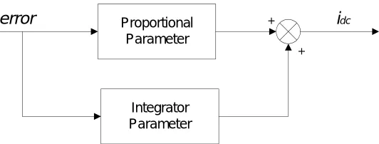
3.3.1.1 PI controller
23
Proportional Parameter
Integrator Parameter
error + idc
[image:32.612.202.468.83.184.2]+
Figure 3.5: PI control algorithm
A PI controller used to control the DC-bus voltage is shown in Figure 3.5. Its transfer function can be represented as:
( ) = + (7)
Where is the proportional constant that determines the dynamic response of the DC-bus voltage control, and is the integration constant that determines the settling time. If and are large, the DC-bus voltage regulation is dominant, and the steady-state DC-bus voltage error is low. The proper selection of and is essentially important to satisfy above mentioned two control performances [31].
3.3.1.2 ANN controller
Figure 3.6: Proposed control algorithm
The controller consists of input layer, hidden layer and output layer. Based on number of the neuron in the layers, the ANN controller is defined as a 1-3-1 network structure. The first neuron of the output layer is used as a voltage reference signal ( = f). The connections weight parameter between jthand ithneuron at mth layer is given by wmij, while bias parameter of this layer at ith neuron is given by bmi. Transfer function of the network at ithneuron in mthlayer is defined by [32]:
1 1 1 m S j m i m j m ij mi w a b
n
(8) The output function of neuron at mthlayer is given by:
)
(
mi m m
i
f
n
a
(9)Where fis activation function of the neuron. In this design the activation function of the output layer is unity and for the hidden layer is a tangent hyperbolic function given by:
1
1
2
)
(
2
mi n m i m
e
n
f
(10) Updating of the connection weight and bias parameters are given by:m ij m ij m ij
w
k
F
k
w
k
w
1
)
(
)
(
)
(
(11) m i m i m ib
k
F
k
b
k
b
1
)
(
)
(
)
(
46
REFERENCES
1. N. A. Rahim Member, IEEE, S. Mekhilef, and Z. Islam. “A New Approach
for Harmonic Compensation Using Single- phase Hybrid Active Power Filter A New Approach for Harmonic Compensation Using Single- phase Hybrid Active Power Filter”. Institute of Research Management and Consultancy, University of Malaya. April 30, 2005.
2. Raymond E. Beighley, Charles A. Gougler, James R. Johnson. “Application of Active Harmonic Filters for Power Quality Improvement”. IEEE 519-1992. 3. M. A. Chaudhari, H. M. Suryawanshi. “Single-Phase Resonant Converter
with Active Power Filter”. IEEE 2006.
4. Ilhami Colak, Ramazan Bayindir, Orhan Kaplan, Ferhat Tas. “DC Bus
Voltage Regulation of an Active Power Filter Using a Fuzzy Logic Controller”. 2010 Ninth International Conference on Machine Learning and Applications.
5. P. Rathika, D. Devaraj. “Fuzzy Logic-Based Approach for Adaptive Hysteresis Band and Dc Voltage Control in Shunt Active Filter”. International Journal of Computer and Electrical Engineering, Vol. 2, No. 3, June, 2010.
6. IEEE standard dictionary of electrical and electronic terms, IEEE Standard 100, 1984.
7. Peng, F.Z., Akagi, H. and Nabae, A. “Compensation characteristics of the combined system of shunt passive and series active filters”, in Proceedings of the IEEE Industry Applications Society Annual Meeting, 1989.
9. Hirofumi Akagi, (MAY 1994). “Trends in Active Power Line Conditioners”,IEEE Transactions on Power Electronic, VOL. 9, NO. 3, 9 (3): pp. 263-268.
10. Akagi, Hirofumi. “New Trends in Active Filters for Power Conditioning”. IEEE Transactions on Industry Application. 1996. 32 (6): pp.1312-1322. 11. Singh, B., Al-Haddad, K. and Chandra, A., “A review of active filters for
power quality improvement”, IEEE Transactions on Industrial Electronics, 46 (5), 960–971, 1999.
12. Zainal Salam, Tan Perng Cheng and Awang Jusoh. “Harmonics Mitigation Using Active Power Filter: A Technological Review”, Elektrika, VOL. 8, NO. 2, 2006, 17‐26
13. G. Blajszczak, “Direct Method for Voltage Distortion Compensation in Power Networks by Series Converter Filter,” Proc. IEE Electric Power Applications, vol. 142, no. 5, pp. 308-312, 1995.
14. B. S. Rigby and R. G. Harley, “The Design and Control of an Inverter-Based Series Compensator for Dynamic Performance,” Proceedings of the IEEE Power Engineering Society Summer Meeting, Alberta, Canada, 1999, pp. 1146-1151.
15. M. El-Habrouk, M. K. Darwish and P. Mehta, “Active Power Filters: A Review,” Proc. IEE Electric Power Applications, vol. 147, no. 5, pp. 403-413, 2000.
16. S. Buso, L. Malesani and P. Mattavelli, “Comparison of Current Control Techniques for Active Filter Applications,” IEEE Trans. on Industrial Electronics, vol. 45, no. 5, pp. 722-729, 1998.
17. T. –F. Wu, C. –L. Shen, J. –Y. Chiu and C. –C. Chen, “An APF with MAPPT Scheme to Improve Power Quality,” Proceedings of the IEEE International Conference on Electrical and Electronic Technology, Singapore, 2001, pp. 620-626.
18. S. Bhattacharya and D. Divan, “Synchronous Frame Based Controller Implementation for a Hybrid Series Active Filter System,” Proceedings of the IEEE Industry Applications Conference, Florida, USA, 1995, pp. 2531-2540. 19. S. J. Chiang, K. T. Chang and C. Y. Yen, “Residential Photovoltaic Energy
48
20. B. Dobrucky, H. Kim, V. Racek, M. Roch and M. Pokorny, “Single-Phase Power Active Filter and Compensator using Instantaneous Reactive Power Method,” Proceedings of the Power Conversion Conference (PCC), Osaka, Japan, 2002, pp. 167-171.
21. T. –F. Wu, C. –L. Shen, C. H. Chang and J. –Y. Chiu, “1/spl phi/ 3W Grid-Connection PV Power Inverter with Partial Active Power Filter,” IEEE Trans. on Aerospace and Electronic Systems, vol. 39, no. 2, pp. 635-646, 2003.
22. B. Dobrucky, H. Kim, V. Racek, M. Roch and M. Pokorny, “Single-Phase
Power Active Filter and Compensator using Instantaneous Reactive Power Method,” Proceedings of the Power Conversion Conference (PCC), Osaka, Japan, 2002, pp. 167-171.
23. H. L. Jou and H. –Y. Wu, “New Single-Phase Active Power Filter,” Proc. IEE Electric Power Applications, vol. 141, no. 3, pp. 129-134, 1994.
24. C. Y. Hsu and H. –Y. Wu, “A New Single-Phase Active Power Filter with Reduced Energy-Storage Capacity,” Proc. IEE Electric Power Applications, vol. 143, no. 1, pp. 25-30, 1996.
25. J. Perez, V. Cardenas, F. Pazos and S. Ramirez, “Voltage Harmonic
Cancellation in Single-Phase Systems using a Series Active Filter with Low-Order Controller,” Proceedings of the IEEE International Power Electronics Congress (CIEP), Guadalajara, Mexico, 2002, pp. 270-274.
26. Donghua Chen, Shaojun Xie, “Review of the control strategies applied to active power filters,” IEEE International Conference on Electric Utility Deregulation, Restructuring and Power Technologies (DRPT2004), Hong Kong, April 2004
27. J. C. Das, “Passive Filters – Potentialities and Limitations,” IEEE Trans. on Industry Applications, vol. 40, no. 1, pp. 232-241, 2004.
28. H. Doğan, R. Akkaya, “A Simple Control Scheme for Single-Phase Shunt Active Power Filter with Fuzzy Logic Based DC Bus Voltage Controller,” Proceedings of the International MultiConference of Engineers and Computer Scientists 2009 Vol II IMECS 2009, Hong Kong, March 18 - 20, 2009
30. M. George and K. P. Basu, “Three-Phase Shunt Active Power Filter”, American Journal of Applied Sciences 5 (8) ,(2008): pp.909-916
31. Kim, S., Yoo, G., and Song, J., “Bifunctional Utility Connected Photovoltaic System with Power Factor correction and U.P.S Facility,”Proceedings of the IEEE Conference on Photovoltaic Specialist. May 13-17(1996). Washington, USA:IEEE.pp.1363-1368
32. Yatim, A.H.M. and Utomo, W.M., “On line optimal control of variable speed
compressor motor drive system using neural control model” Proceeding National Power and Energy Conference, PECon 2004, PED-8,pp.83-87 33. P. Salmeron and J. R. Vazquez, “Active Power-line conditioners,” University
of Huelva: pp. 259-262
34. B. Ismail,S.Taib MIEEE, A. R Mohd Saad, M. Isa and C. M. Hadzer. “Development of a Single Phase SPWM Microcontroller-Based Inverter”. First International Power and Energy Conference PECon 2006, November 28-29, 2006, Putrajaya, Malaysia.
35. Mohan,N,Undeland, T and Robbins, W(1995), “Power Electronics-Converters, Application, and Design,”. 2nd.edition. Canada:John Wiley & Sons, Inc