doi: 10.1093/jmicro/dfp055
. . . .
Biological: Full-length
Structural analysis of hydroxyapatite coating on magnetite
nanoparticles using energy filter imaging and electron
tomography
Mitsuhiro Okuda
1,2, Masaki Takeguchi
2, ´
Orla ´
O Ruairc
3, Motohiro Tagaya
1,
Yufang Zhu
4, Ayako Hashimoto
4, Nobutaka Hanagata
1, Wolfgang Schmitt
3and Toshiyuki Ikoma
1∗1Biomaterials Center, National Institute for Materials Science, 1-2-1 Sengen, Tsukuba, Ibaraki, 305-0047,
Japan,2Advanced Nano-Characterization Center, National Institute for Materials Science, 3-13 Sakura,
Tsukuba, Ibaraki, 305-0003, Japan,3School of Chemistry, Trinity College Dublin, Dublin 2, Ireland and
4International Center for Young Scientists, National Institute for Materials Science, 1-2-1 Sengen, Tsukuba,
Ibaraki, 305-0047, Japan
∗To whom correspondence should be addressed. E-mail: [email protected]
. . . . Abstract Magnetic nanoparticle (MNP) composites with a magnetite (Fe3O4) core
and a hydroxyapatite (HAp, Ca10(PO4)6(OH)2) coating were prepared
us-ing a precipitation method and a subsequent hydrothermal treatment. The hydrothermal treatment diminished the lepidocrocite layer on the mag-netite, enhanced the crystal growth of HAp and dissolved the MNPs. The divalent iron ions dissolved into solvent were not substituted for the HAp lattice. The three-dimensional (3D) nanostructure, the crystal morphology of HAp covered with the MNPs and the interfacial nanostructure of mag-netite/HAp were analyzed using an energy-filter transmission electron mi-croscopy (EF-TEM) and visualized by computer tomography in transmis-sion electron microscopy (TEM). EF-TEM and 3D reconstruction images using a tilted series of high-angle annular dark-field images showed that the needlelike HAp nanocrystals covered with a magnetite core and the crystal growth of HAp attached to the magnetite surface was inhibited as a result of the lower density of the nucleation site of the lepidocrocite layer. The dissolution of iron ion from MNPs and the interfacial interac-tion of HAp and magnetite could cause the needlelike morphology of HAp nanocrystals.
. . . . Keywords electron tomography, magnetite, hydroxyapatite, magnetic nanoparticle,
hyperthermia, MRI
. . . . Received 27 August 2009, accepted 29 September 2009, online 6 November 2009
. . . .
Introduction
Magnetic nanoparticles (MNPs) have attracted a great deal of attention in biomedical applications such as biomolecular separation, targeted drug deliv-ery, a contrast agent for magnetic resonance imaging (MRI) and cancer diagnosis on hyperthermia [1]. In particular, magnetite (Fe3O4) and maghematite (γ
-Fe2O3) have been widely investigated, as two of the
most promising MNPs for biomedical materials be-cause of their superior magnetic properties and bio-compatibility with relatively low toxicity and high metabolic characteristics. Furthermore, a short T2 relaxation time and high-saturation magnetization make it possible to enhance the image contrast of MRI and the effectiveness of cancer diagnosis on hyperthermia.
. . . .
c
The Author 2009. Published by Oxford University Press [on behalf of Japanese Society of Microscopy]. All rights reserved. For permissions, please e-mail: [email protected]
at Trinity College Dublin on April 7, 2014
http://jmicro.oxfordjournals.org/
Surface modification of the MNPs, for practical application, is indispensable to improve functions such as biomolecular recognition and stability in tis-sues and cells. Many researchers have explored the coating materials on MNPs by means of the intro-duction of functional groups, ligand–receptor reac-tions and with the improved structural stability and solubility in tissues, such as dextran [2], polyethy-lene glycol [3], silica [4], gold [5] and hydroxyap-atite (HAp, Ca10(PO4)6(OH)2) [6,7]. HAp shows
ex-cellent biocompatibility and has been investigated as a drug delivery carrier [8]. Some researchers have already described ‘Magnetite-HAp composites’ using co-precipitation [6] and hydrothermal methods [7] and have examined their magnetic properties for hy-perthermia applications. However, it has not been made clear whether the composites were mixture-or epitaxially grown on magnetite surfaces, which in-troduce a chemical binding among each other.
Recently, we described how crystalline HAp pre-cipitates grow on magnetite nanoparticles through a biomimetic process—biomineralization; to mimic the tooth of chiton, HAp nanocrystals were formed through a lepidocrocite (γ-FeOOH) intermediate layer on a magnetite layer [9]. Thus, we produced a lepidocrocite layer on the surface of magnetite MNPs like chiton teeth and then formed the HAp us-ing a layer-by-layer technique [10]. However, it was not clear whether HAp directly adhered to the mag-netite surface to form the expected core/shell struc-ture successfully. A detailed understanding of the nu-cleation process and the growth of HAp on magnetite MNPs is needed to optimize the condition of HAp coating.
High-resolution imaging, such as scanning electron microscopy (SEM), atomic force microscopy (AFM) and scanning tunnel microscopy (STM), are useful for the observation of micro- to nano-structures, for which techniques are limited in surface imaging and are unsuitable for characterizing the core/shell in-terface structure. Conventional transmission elec-tron microscopy (TEM) is a powerful tool for imag-ing internal structures but cannot readily distimag-inguish the three-dimensional (3D) features of the inter-facial structure between core and shell materials. On the other hand, computer tomography (CT) in TEM (TEM-CT) has been developed, and thereby 3D analyses with a nanometer scale are
avail-able in high resolution for the complex core/shell structures [11].
This paper aims at revealing the nano-level inter-facial structure of a magnetite core and HAp coat-ing uscoat-ing TEM-CT. The structures of magnetite/HAp MNP composites prepared by biomimetic miner-alization are three-dimensionally reconstructed by TEM-CT, followed by an extraction of images sliced at specific sites with nanometer resolution. Com-bining with elemental imaging by energy-filtered transmission electron microscopy (EF-TEM), the in-terfacial structure of HAp adhesion on magnetite is elucidated, and the process of nucleation and growth of HAp on magnetite MNP are discussed.
Materials and methods
Sample preparation
A method proposed by Denget al.was employed to fabricate a magnetite MNP [12]. FeCl3·6H2O (1.35 g,
5 mmol) was dissolved in ethylene glycol (40 mL), followed by the addition of sodium acetate (3.6 g) and polyethylene glycol (1.0 g). The mixture was stirred vigorously for 30 min and then sealed in a Teflon-lined stainless-steel autoclave (300 mL capac-ity). The autoclave was heated at 200◦C for 8 h in an oven. After cooling to room temperature, the black products were washed several times with ethanol and dried at 60◦C for 6 h and then dispersed in ethanol to form a 1 wt% magnetite suspension.
Magnetite/HAp MNP composites were pre-pared by a precipitation method and the subse-quent hydrothermal method. Hundred milliliter of K2HPO4·3H2O solution (24 mmol L−1) was heated at
80◦C, and the pH was controlled by means of a KOH solution (5 mol L−1), and 1 mL of magnetite
suspen-sion was then added and stirred for 30 min. Hundred milliliter of CaCl2 solution (40 mmol L−1) was added
at the rate of 25 mL min−1 into the high-alkaline
magnetite suspension. The final solution at pH 9.0 was transferred into a Teflon-lined stainless steel autoclave (300 mL, capacity) and heated at 160◦C for 24 h in an oven. This suspension had a Ca/P ratio of 1.67, which is equal to a stoichiometric ratio of HAp. After cooling to room temperature, the resultant suspension was centrifuged at 20 000 g(196 000 m s−2) for 10 min. The collected products were washed
at Trinity College Dublin on April 7, 2014
http://jmicro.oxfordjournals.org/
three times with distilled water and three times with ethanol by centrifuge.
For X-ray powder diffraction (XRD) analysis, magnetite/HAp MNP composites in water were dried in an oven at 60◦C. The crystalline phase of the product was analyzed using an X-ray diffractometer (Rigaku Ultima IIIc) under CuKαradiation at 40 kV
and 40 mA in the 2θrange of 10–75◦.
For TEM and SEM observations, the sample in ethanol was sonicated for 10 min, and 5 μL of the suspension was dropped onto a carbon film on a Cu mesh grid. After drying the mesh in air, the grid was immersed in 3 mL of ethanol for 5 min to completely wash the organic substances and then dried again.
Morphological analyses
Surface morphologies of the magnetite nanoparticles and the magnetite/HAp MNP composites were ob-served with a field emission SEM (FE-SEM, JEOL 7000F) at an accelerating voltage of 30 kV.
Elemental mapping by EF-TEM was performed on a JEOL 3000F filed emission TEM equipped with a Gatan imaging filter (Model 863 GIF Tridiemc) and
a 2 k × 2 k charge-coupled device (CCD) camera (Ultrascanc). EF-TEM images of calcium (L edge,
347 eV), oxygen (K edge, 535 eV) and iron (L edge, 710 eV) maps were obtained by the three-window method.
The tilt series acquisition of high-angle annular dark-field scanning TEM (HAADF-STEM) images was performed on a JEOL 2100F field emission TEM equipped with an ADF detector (EM-24560, JEOL) and a digital image acquisition system (Digiscan IIc,
GATAN). The sample grid was placed in a holder (EM-21311HTR, JEOL), and the tilt series of a mag-netite/HAp MNP composite was recorded from+60◦ to−60◦at 2◦decrements, giving a total of 61 images. The inner and outer semi-angles of the ADF detec-tor for HAADF-STEM imaging were 71 and 190 mrad, respectively. In HAADF-STEM imaging, a 800 × 800 nm2 area was acquired at the size of 1024 ×
1024 pixel2 at an exposure time of 63 s/frame in-cluding a dwell time of 60 μs/pixel. Acquisition of the tilt series was performed by the 3D Tomog-raphy Softwarec (GATAN) with automatic
[image:3.612.331.531.62.230.2]func-tions of stage tracking assist and dynamic focus-ing. In-focusing on acquisition of tilt series was
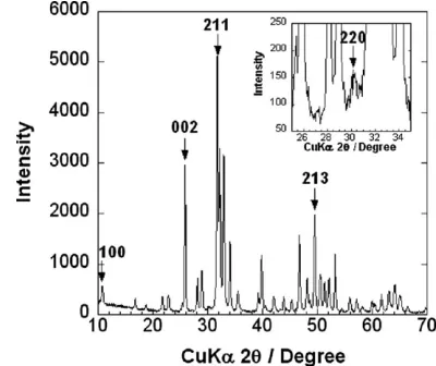
Fig. 1.XRD pattern of magnetite/HAp MNP composites treated with
a hydrothermal treatment. Index of (100), (002), (211) and (213) in the figure indicates Miller’s indices of HAp. The inset figure shows the ex-pansion of the XRD pattern around (220) diffraction of magnetite. All diffraction peaks except (220) at 30.1◦are attributed to HAp (JCPDS 09-0432).
adjusted manually. After extracting selected area tilt series (600 × 600 pixel2 image) from row tilt
se-ries, an image alignment with band pass filter and 3D reconstruction using the simultaneous iterative reconstruction technique (SIRT) with 40 iterations were calculated by the 3D Tomography Softwarec
(GATAN).
Results and discussion
Figure 1 shows the XRD pattern of magnetite/HAp MNP composites treated with hydrothermal treat-ment. These diffractions corresponded to HAp and magnetite. The typical diffractions of (100), (002), (211) and (213) attributed to the HAp phase and the maximum diffraction of (220) at 30.1◦ in 2θ de-gree attributed to the magnetite were detected, re-spectively. It should be noted that the diffractions in the lepidocrocite phase were indistinguishable. As we previously described [10], the magnetite/HAp MNP composites before the hydrothermal treatment showed a XRD diffraction of the lepidocrocite at 26◦ in 2θ degree, and a typical infrared (IR) adsorp-tion peak attributed to the lepidocrocite at 758 cm−1,
suggesting that there was an intermediate layer be-tween the magnetite and HAp [12]. The IR adsorp-tion peak at 758 cm−1 of the magnetite/HAp MNP composites after hydrothermal treatment was in-distinguishable (data not shown). In the hydrother-mal treatment, the lepidocrocite layer in the MNPs
at Trinity College Dublin on April 7, 2014
http://jmicro.oxfordjournals.org/
Fig. 2.FE-SEM images of (a) magnetite spherical MNPs and (b) a magnetite/HAp MNP composite that were covered by needlelike HAp nanocrystals.
composite did not appear because the hydrother-mal treatment can transfer the hydrotherhydrother-mally un-stable lepidocrocite to the magnetite. The amount of magnetite crystals apparently decreased during the hydrothermal process due to the dissolution of the magnetite in an alkaline solution. On the other hand, the crystallinity of HAp in the MNPs hydrother-mally treated was higher than that of the HAp pre-cipitation, indicating that HAp nanocrystals had been grown.
Figure 2 shows FE-SEM images of (a) magnetite MNPs and (b) magnetite/HAp MNP composites. The magnetite spherical MNPs as shown in Fig. 2a were constructed by an aggregation of cuboidal nanocrys-tals, 20–40 nm in size, with a spherical diameter of 100–250 nm. The spherical nanoparticles covered with needlelike crystals are shown in Fig. 2b, and larger platelike crystals were also observed around the spherical nanoparticles. While the platelike crys-tals measured 100–150 nm in length and 15–30 nm in width, the needlelike nanocrystals apparently were of a smaller size, measuring 70–90 nm in length and 5–15 nm in width. From the results of the XRD pat-tern, the platelike and needlelike nanocrystals were HAp, and the morphological differences could be at-tributed to the interaction of magnetite and HAp in the crystal growth. Thus, the interfacial structure of magnetite and HAp in the MNP was of importance to elucidate the mechanism of HAp crystal growth.
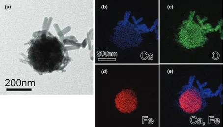
Figure 3 shows (a) TEM and EF-TEM images of a magnetite/HAp MNP composite and the elemental maps of (b) calcium, (c) oxygen, (d) iron, and (e)
superimposed RB map of calcium and iron. There are three different morphologies with a gray contrast with needlelike nanocrystals aggregating around a centered spherical large particle with dark con-trast and platelike nanocrystals. It should be noted that the needlelike nanocrystals cover the magnetite MNP surface, while the platelike nanocrystals are distributed around the spherical particle. Figure 3e is the superimposed image of Fig. 3b and d. It is clear that the spherical large particle is composed of iron and oxygen. On the other hand, the platelike and needlelike crystals contained calcium and oxygen, and the electron energy loss spectra of the platelike and needlelike crystals confirmed the presence of phosphorus. Combining with the results of the XRD pattern, it was identified that the spherical large par-ticle is crystalline magnetite, and both the platelike and needlelike crystals are HAp. The iron exists only in the magnetite spherical MNPs, as shown in Fig. 3e, suggesting that the substitution of iron dissolved in the solvent in the apatite lattice could not occur dur-ing the hydrothermal treatment.
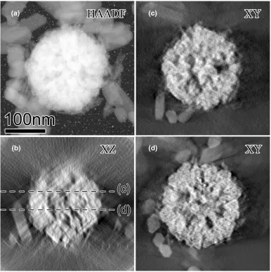
Figure 4 shows (a) HAADF-STEM image at a tilt-ing angle of 0◦ and the sliced HAADF-STEM im-ages of (b)xzand (c and d)xydirections extracted from the 3D reconstructed volume of the magnetite/ HAp MNP composite. HAADF-STEM generally pro-vides the minimization of unfavorable diffraction contrast and the atomic number (Z)-dependent high contrast image, the high contrast of which in a tilt series offers a tremendous advantage to 3D to-mography reconstruction [11]. The Z-contrast of a
at Trinity College Dublin on April 7, 2014
http://jmicro.oxfordjournals.org/
Fig. 3.TEM and EF-TEM images of a magnetite/HAp MNP composite. (a) TEM image, (b) calcium, (c) oxygen, (d) iron and (e) RB map (calcium, blue; and iron, red) maps. The elemental distributions were obtained by the three-window method. Calcium element distribution around the iron-containing particle is clearly observed.
heavy element such as iron shows a bright image. In this study, the sliced images extracted from the 3D reconstructed volume, as shown in Fig. 4b–d, clearly indicate that the internal nanopores in the magnetite spherical nanoparticle and the dimension of magnetite nanocrystals aggregated at 10–20 nm in size.
The sliced images at specific directions of lon-gitudinal and header planes of nanocrystals are also available for length measurement. The platelike nanocrystals had 106.9 ± 33.4 nm and 37.8 ± 5.3 nm with an aspect ratio of 2.8, and the needlelike nanocrystals had 84.8 ± 26.1 nm and 8.6± 1.6 nm with an aspect ratio of 9.9. The hydrothermal treat-ment promotes HAp crystal growth as the platelike morphology; interestingly, the HAp covered with the magnetite spherical MNPs showed a different mor-phology with smaller needlelike crystals of HAp. The inhibition of HAp crystal was attributed to the dis-solved divalent iron ions [13].
Obviously, the needlelike HAp nanocrystals shown in Fig. 4c and d were not evenly covered, with the surfaces of the magnetite spherical nanoparticles in random directions, but HAp crystal growth was ini-tiated on the magnetite surface with tip or side
at-tachments. It is known that the lepidocrocite inter-mediate layer on magnetite spherical MNPs plays an important role as a nucleation site for HAp growth. In our previous report [10], there was a lepidocrocite layer detectable by XRD and IR in the magnetite/ HAp MNP composites prepared using a precipitation method. The hydrothermal treatment reduced the lepidocrocite layer undetectable by XRD and TEM-CT, and thus HAp coverage was limited due to the lower density of the nucleation sites. Both disso-lution of iron ions from magnetite spherical MNPs and the interfacial interaction of HAp and magnetite could strongly affect the crystal growth of HAp.
Concluding remarks
MNP composites with a magnetite core and a HAp coating were successfully prepared using the precip-itation method and subsequent hydrothermal treat-ment. The results of EF-TEM and the 3D recon-structed TEM-CT images showed that the magnetite/ HAp MNP composites were composed only of needlelike HAp nanocrystals covering the magnetite spherical MNPs that had internal nanopores. The crystal growth of needlelike HAp nanocrystals was restricted due to the effects of the dissolved divalent
at Trinity College Dublin on April 7, 2014
http://jmicro.oxfordjournals.org/
Fig. 4.HAADF-STEM images extracted from 3D reconstruction by TEM-CT of a Fe3O4core and HAp coating. (a) HAADF-STEM image, (b)
xzsliced image including the sliced depth ofxyimages as dashed lines, and (c and d)xysliced images at different depths. Supplementary information shows the movie ofxysliced images.
iron as well as the interfacial interaction of HAp and magnetite. The coverage of HAp on the magnetite surface was limited due to the lower density of nu-cleation sites of lepidocrocite for HAp nanocrystals.
Supplementary data
Supplementary data are available at http://jmicro. oxfordjournals.org/.
References
. . . .
1 Mornet S, Vasseur S, Grasset F, and Duguet E (2004) Magnetic nanoparticle design for medical diagnosis and therapy. J. Mater. Chem.14: 2161–2175.
. . . .
2 Berry C C, Wells S, Charles S, and Curtis A S G (2003) Dextran and albumin derivatised iron oxide nanoparticles: influence on fibroblasts
in vitro.Biomaterials24: 4551–4557.
. . . .
3 Inada Y, Ohwada K, Yoshimoto T, Kojima S, Takahashi K, Kodera Y, Matsushima A, and Saito Y (1987) Fibrinolysis by urokinase endowed with magnetic property.Biochem. Biophys. Res. Commun.148: 392– 396.
. . . .
4 Tartaj P, Gonzμlez-Carreæo T, and Serna C J (2001) Single-step nano-engineering of silica coated maghemite hollow spheres with tunable magnetic properties.Adv. Mater.13: 1620–1624.
. . . .
5 Chen M, Yamamuro S, Farrell D, and Majetich S A (2003) Biological applications: particles and sensors.J. Appl. Phys.93: 7551–7553.
. . . .
6 Wu H C, Wang T W, Sun J S, Wang W H, and Lin F H (2007) A novel biomagnetic nanoparticle based on hydroxyapatite.Nanotechnology
18: 165601
. . . .
7 Murakami S, Hosono T, Jeyadevan B, Kamitakahara M, and Ioku K (2008) Hydrothermal synthesis of magnetite/hydroxyapatite compos-ite material for hyperthermia therapy for bone cancer.J. Ceram. Soc. Japan.116: 950–954.
. . . .
8 Ikoma T, Tonegawa R, Watanabe H, Chen G P, Tanaka J, and Mizushima Y J (2007) Drug-supported microparticle of calcium car-bonate nanocrystals and its covering with hydroxyapatiteJ. Nanosci. Nanotechnol.7: 822–827
at Trinity College Dublin on April 7, 2014
http://jmicro.oxfordjournals.org/
. . . .
9 Wealthall R J, Brooker L R, Macey D J, and Griffin B J (2005) Fine structure of the mineralized teeth of the chitonAcanthopleura echi-nata(Mollusca: polyplacophora).J. Morphol.265: 165–175.
. . . .
10 ´O Ruairc ´O, Tonegawa T, Tagaya M, Okuda M, Takeguchi M, Zhu Y, Hanagata H, Schmitt W, Ikoma T (2009) Biomimetic approach to lepidocrocite-mediated magnetite-hydroxyapatite nanocomposites materials letter. Submitted.
. . . .
11 Midgly P A, and Weyland M (2003) 3D electron microscopy in the phys-ical sciences: the development of Z-contrast and EFTEM tomography.
Ultramicoscopy96: 413–431.
. . . .
12 Deng H, Li X, Peng Q, Wang X, Chen J, and Li Y (2005) Monodisperse magnetic single-crystal ferrite microspheres.Angew. Chem. Int. Ed.
44: 2782–2785.
. . . .
13 Morrissey R, Rodriguez-Lorenzo L M, and Gross K A (2005) Influ-ence of ferrous iron incorporation on the structure of hydroxyapatite.
J. Mater. Sci. Mater. Med.16: 387–392.
at Trinity College Dublin on April 7, 2014
http://jmicro.oxfordjournals.org/