Researches for a Decommissioning Device Development
Concept of the Horizontal Fuel Channel in the CANDU 6
Nuclear Reactor: Presentation, Functioning
and Operating
Gabi Rosca-Fartat*, Constantin Popescu, Nicolae Pana
The Faculty of Engineering and Management of Technological Systems, Polytechnic University, Romania
Copyright©2017 by authors, all rights reserved. Authors agree that this article remains permanently open access under the terms of the Creative Commons Attribution License 4.0 International License
Abstract
This paper present a possible method for decommissioning of the horizontal fuel channels in the CANDU 6 nuclear reactor, a new device design concept solution with an operating panel. The device shall be designed according to the radiation protection procedures. The horizontal fuel channels decommissioning device from the CANDU 6 nuclear reactor is an electromechanical system with many freedom degrees, able to perform the internal components extraction and manage the storage into the waste container. The operations are performed under the control of a system equipped with a Programmable Logic Controller (PLC) and monitored by an operator panel, Human Machine Interface (HMI) type. The fuel channel decommissioning device ensures full radiation protection of workers and environment during the dismantling stages.Keywords
CANDU Reactor, Fuel Channel, Decommissioning Device, Dismantling, Operator Panel, Cutting, Extraction1. Introduction
The nuclear reactors are designed and manufactured in respect with the specific requirements of codes and standards described in the AECL (Atomic Energy of Canada Limited), specified documents for fabrication of components, equipment and systems, required for the construction and operation of CANDU nuclear reactor into the power plant.
The decommissioning activities are: dismantling, demolition, controlled removal of equipment, components, conventional or hazardous waste (radioactive, toxic) in compliance with the international basic safety standards on radiation protection.
The decommissioning device concept proposes an assembly composed by two main parts: the device itself and
a flexible platform support for coupling to the selected channel to be dismantled.
The fuel channel decommissioning device is an autonomous device designed for dismantling and extraction of the channel closure plug and shield plug, extraction of the end fitting, cutting and extraction of the pressure tube.
2. Fuel Channel – the Main Components
The CANDU 6 reactors are the following general features of the fuel channels:
380 fuel channels/reactor;
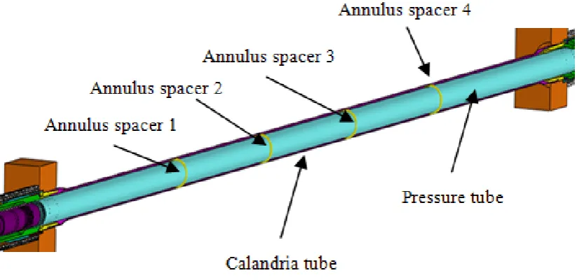
each fuel channel reactor has as main components: one pressure tube made by Zi 2,5% NB (diameter 103,4
mm, thickness 4,19 mm) inside one calandria tube made by Zircaloy 2 (diameter 129,0 mm, thickness 1,37 mm) four annulus spacers made by Incon.X750 (coil diameter 4,83 mm, 4 pieces) which ensure the gap between pressure and calandria tubes;
twelve fuel bundles by fissile isotopes (U235, Pu239) and fertile materials (U238, U232); as remark: the fuel bundles are removed from reactor channel long time before starting decommissioning process. [3] [9] [24] The time life of the fuel channel is for 30 years at 80% of its capacity and 24 years for full capacity functioning.
These main components are illustrated in the Figure 1. [9]
2.1. Calandria Reference Plans
For the installation of the fuel channel into the calandria CANDU nuclear reactor, shall defining the reference plans, measurements reported to reference plans which to comply the requirements described in the AECL (Atomic Energy of Canada Limited) specified documents. [1] [3] [6] [9]
Figure 1. Main components of the fuel channel
Figure 2. Schematic illustration of the reference plans for measurements making at fuel channel installation
The plans determination operations are as follows: preliminary determination of the R plan; preliminary determination of the R' plan;
establishing of the R plan reference and markers reference;
distance determining between P and P' plans reference, front and back calandria plane;
[image:2.595.100.514.318.665.2]The measurements for fuel channel length calculation provide three fuel channels category:
A channel category - nominal length of 10,850 mm; B channel category - nominal length of 10 836 mm; C channel category - nominal length of 10,820 mm;
The distance measurements from the plan R or R' to end fitting for fuel channel type is prepared to:
R-A / R'-A' = 213,36 mm; R-B / R'-B' = 220,98 mm; R-C / R'-C' = 228,60 mm.
[image:3.595.96.510.422.668.2]The registration document of the fuel channel length calculation for each channel type contains information about channel elements length, shown in table 1.
Table 1. Channel elements length
Channel
category length PT (mm) Pressure tube
Sub-assembly length EF-PT
(mm)
Final length of FC (mm)
A X-1496,57 X+765,61 X+3027,68
B X-1511,81 X+730,37 X+3012,44
C X-1527,05 X+735,13 X+2997,20
where: EF-End Fitting, PT-Pressure Tube, FC-Fuel Channel and X measured distance between P and P' plane.
All registration documents check documents and relating reports to the installation of the fuel channel are part of the
registration procedure of the reactor assembly process.
2.2. General Presentation of the Fuel Channel
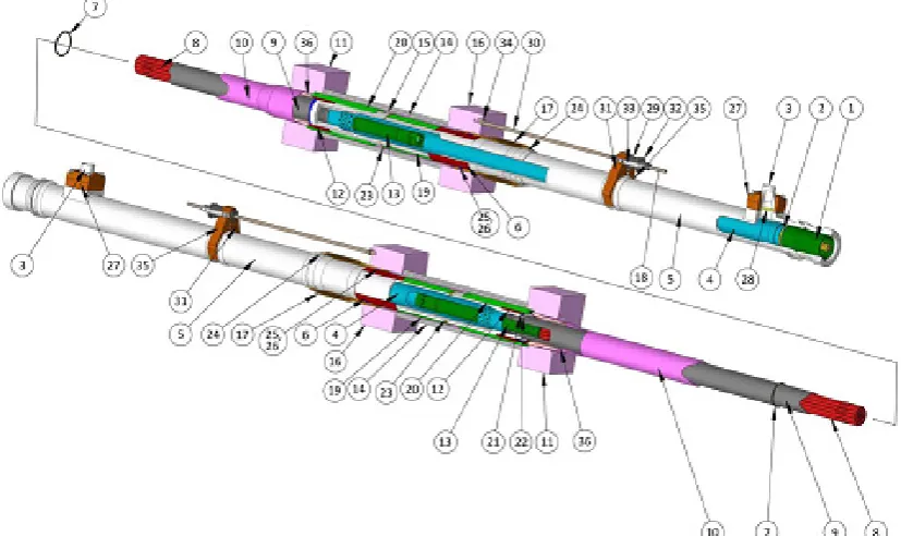
The fuel channels are the main features of a CANDU reactor, and their reliability is crucial to the performance of the reactor. The components of the fuel channel design are illustrated in Figure 3.
1. Channel closure plug; 2. Closure seal insert; 3. Feeder coupling; 4. Liner tube; 5. End fitting body; 6. Outboard bearings; 7. Annulus spacer; 8. Fuel bundle; 9. Pressure tube; 10. Calandria tube; 11. Calandria tubesheet; 12. Inboard bearings; 13. Shield plug; 14. Endshield shielding balls; 15. Endshield lattice tube; 16. Fuelling tubesheet; 17. Channel annulus bellows; 18. Positioning assembly; 19. End fitting shielding sleeve; 20. Lattice tube shielding sleeve; 21. End fitting inner ring seal; 22. Elastic safety lock for end fitting inner ring seal; 23. Elastic safety lock for end fitting shielding sleeve; 24. Support ring for annulus bellows; 25. Annulus bellows outer ring seal; 26. Elastic safety lock for Annulus bellows outer ring seal; 27. Feeder coupling attachment; 28. Feeder gasket; 29. Rod positioning threaded part; 30. Rod positioning; 31. Right fastening piece for rod positioning; 32. Counter nut locking; 33. Safety lock for counter nut; 34. Lock pin for rod positioning; 35. Left fastening piece for rod positioning; 36. Crimping ring for calandria tube. [2] [3] [6] [9] [23] [24]
3. Decommissioning device concept
This concept aims to achieve the requirements of nuclear materials, regarding the nuclear radiation.
Hereunder is shown the nuclear radiation half-life for each isotope:
U235 has 704 million years U238 has 4.468 billion years Pu239 has 24110 years
That it means during handling of these materials we have to consider all possible protection rules as mandatory to be applied.
The dismantling of fuel channels components is a complex process that requires piece by piece removal activities. All operations shall be performed by a remote controlled decommissioning device, able to perform all operations in decommissioning process as follows: extracting the channel closure plug and the channel shield plug, cutting the pressure tube (PT) in two parts during extracting phase of it, extract the end fitting (EF).
All operations performed achieve the maximum radiation protection degree and represent a safety solution to protect the operators and the environment. [7] [14] [22]
3.1. Device Assembly Components Presentation
[image:4.595.315.548.227.287.2]The device assembly for fuel channel components decommissioning is composed of the device itself (1) and moving platform (2) that contains the device support assembly (3) for front alignment at the fuel channel (Figure 4).
Figure 4. Schematic illustration of the device assembly components
The moving platform allows precise positioning in front of the fuel channel which shall be decommissioned. The device support assembly is required for positioning the decommissioning device at the fuel channel which shall be dismantled.
3.2. Decommissioning Device Components Presentation
The decommissioning device is able to perform the following operations:
the storage of the channel closure plug extracted from the end fitting;
the storage of the channel shield plug extracted from the liner tube;
the storage of the pressure tube extracted from the fuel channel;
the storage of the end fitting.
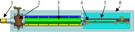
[image:4.595.315.548.382.484.2]The parts of decommissioning device concept are illustrated in the Figure 5: the coupling and locking fuel channel module (1), the safety valve assembly to the fuel channel (2), the storage tubes assembly for extracted components (3), the handling elements assembly (4), the cutting and extraction device (5) and the housing device (6).
Figure 5. Schematic illustration of the device components
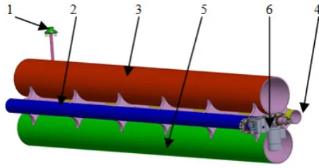
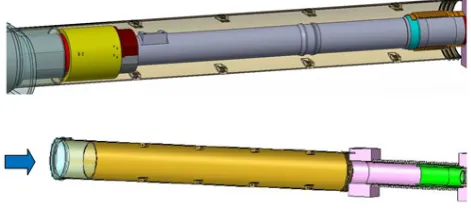
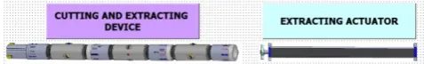
[image:4.595.63.292.474.575.2]The cutting and extraction device consists of the following modules: guiding-fixing module (1), traction modules (2), guiding-fixing module at cutting (3), cutting module (4), guiding-extracting module (5) articulated elements (6) for modules connecting and command cable (7) (see Figure 6).
Figure 6. Representation of the cutting and extraction device components
3.3. Coupling and Locking Fuel Channel Module
Figure 7. Representation of the coupling and locking module to the fuel channel
[image:4.595.316.548.531.631.2]fuel channel (1). After fuel channel module coupling, is mounted a protective cylindrical shield, made by two semicircular pieces, assembled with screws. This shield covers the end fitting for the radiation protection of the operator, after extraction of the fuel channel end fitting, exemplified in Figure 7).
3.4. Safety Valve Assembly Presentation
[image:5.595.67.284.237.344.2]The safety valve allows the access of handling elements into the fuel channel to achieve the dismantling operations, and consist of the safety valve itself (1) and the actuator (2), exemplified in Figure 8.
Figure 8. Representation of the safety valve of the device
3.5. Storage Tubes Assembly Presentation
[image:5.595.63.289.442.561.2]The storage tubes assembly is used to receive the extracted components of the fuel channel, as a result of the dismantling operations, exemplified in Figure 9.
Figure 9. The storage tube assembly components
The storage tubes assembly is mounted on a shaft driven by a gear motor to turning it in order to place a tube in front of the access valve for access to the fuel channel.
The storage tubes are used as follows:
the Blue tube for storage of the pressure tube; the Red tube for the fitting end storage;
the Yellow tube for storage of the channel closure plug and the channel shield plug;
the Green tube for storage of the extended channel closure plug.
3.6. The Handling Elements Assembly
The handling elements assembly is composed of the sleigh
assembly (1), the sleigh travel actuator (2), the stationary tube of the cutting and extraction device (3), connecting cable roller of the cutting and extraction device (4), the extracting actuator of the end fitting (5), exemplified in Figure 10.
Figure 10. The handling elements assembly
The handling elements assembly can operate two positions in order to place one element front of the storage tube: one position is when the stationary tube it is in working
direction for the movement of the cutting and extraction device; cable roller realize the cable progress or tightening of the cutting and extraction device in time of displacement; the operations are the extraction of the channel closure plug, the channel shield plug, cutting and extraction of the pressure tube;
the second position is when the extracting actuator it is in working direction; the operations are extraction of the end fitting, installation or removal of the extended channel closure plug.
4. General Steps of Components
Dismantling
The fuel channels dismantling is a complex process and requires activities such as locking/unlocking the channel closure plug and the shield plug, pressure tube cutting, extracting of the components from inside of the nuclear reactor channel, as well as radioactive waste management. When the extraction steps are completed, the decommissioning device is displaced to the transport container for transfer and storage of the dismantled components in the dedicated facilities.
4.1. General Consideration
The dismantling of fuel channel components is performed when the initial conditions are reached: no fuel bundles in the fuel channels, the cooling system should be empty by coolant, the feeders coupling of each feed pipes are removed and the connection is covered with a lid.
The decommissioning operations of a fuel channel should be identical repeated the all of 380 fuel channels of the nuclear reacto, from the front side (plane R), to the rear side (plane R ') of calandria.
4.2. Mounting of the Device on the Moving Platform
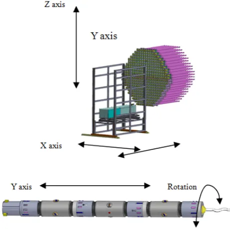
This platform perform the movement of the device, parallel with the plane of the reactor (horizontal and vertical) in order to align it with one of the 380 fuel channels.
The platform support for moving and positioning device has 2 freedom degrees due to the X-axis movement (horizontal movement) and Z axis (vertical movement). The cutting and extraction device perform a forward/retreat movement along the Y axis and a rotational movement along the Y axis, so that it has two freedom degrees, as exemplified in Figure 11.
Figure 11. Representation of the platform support and cutting and extraction device degrees of freedom
4.3. Dismantling of the Positioning Assembly
[image:6.595.62.293.344.574.2]Before to start of the fuel channel decommissioning operations, should be manually performed the positioning assembly dismantling (see Figure 12).
Figure 12. Representation of the positioningassembly removal
4.4. Decommissioning Device Coupling to the Fuel Channel
The coupling of the device to the fuel channel is performed manually by the operator. The coupling and fixing steps are (see Figure 13):
platform moving to the fuel channel which will be dismantled;
moving the decommissioning device to the position that the coupling/extraction head is under the end fitting and then this is lifted to a contact position with the end fitting;
introduce the auxiliary piece (brown piece) for coupling/extraction head closing;
locking cylinder (yellow piece) of the coupling/extraction head moving in the "locked" position;
[image:6.595.314.548.344.462.2] mounting of the protective cylindrical screen, made from two semicircular pieces by screws joined, which cover the end fitting, for the operator radiation protection after the fuel channel end fitting extraction;
Figure 13. Representation of the device coupling steps and the protective cylindrical screen mounting device mounting and positioning
4.5. Dismantling of the Fuel Channel Components
After the device is coupled to the fuel channel it’s possible to proceed to the fuel channel dismantling operations. The components dismantling operations to the fuel channel are performed by the operator, on the decommissioning device operator panel.
4.5.1. Removal of the Fuel Channel Closure Plug and the Shield Plug
For the closure plug removal the preliminary operations are:
the storage tube assembly rotation command so that the tube for the pressure tube storage (the blue tube) to reach the working position, coaxial with the axis of the fuel channel reactor;
the opening command of the device safety valve assembly;
[image:6.595.62.304.686.735.2]After finishing the preliminary operations, the operator command the cutting and extraction device to moving, unlocking, extraction and storage of the channel closure plug in the yellow tube (see Figure 14). [6] [9]
Figure 14. Representation of the channel closure plug extraction
[image:7.595.57.297.336.448.2]After extraction and storage of the channel closure plug, the operator command the cutting and extraction device to moving, unlocking, extraction and storage of the shield plug in the yellow tube (see Figure 15). [6] [9]
Figure 15. Representation of the shield plug extraction and plugs storage
4.5.2. Cutting of the Pressure Tube
For pressure tube cutting it is necessary to bring the blue tube in the working position (see Figure 16). [6] [9]
Figure 16. Representation of the cutting in the middle of the pressure tube
The second step of the pressure tube cutting operation is the positioning of the cutting and extraction device at the end of the pressure tube at the joint with the end fitting and blocking the guiding-fixing module claws.
After positioning and blocking, the operator commands the cutting module to start the cutting operation. The cutting operation is monitored by video camera, for cutting viewing, and pyrometer for temperature recording in the cutting area
(see Figure 17).
Figure 17. Representation of the cutting at the end of the pressure tube
After the end of the cutting operations, the cutting and extraction device is retreated in the stationary tube from the handling elements assembly.
The cutting operations are monitored by video camera and pyrometers for recording the temperature in the cutting rollers area.
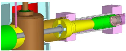
4.5.3. Extraction of the End Fitting
The end fitting extraction preliminary operations are performed by dragging the handling elements assembly that the extracting actuator of the end fitting and the red tube from the storage tubes assembly reach the working position.
The operator commands the extension of the extracting actuator until the coupling and blocking with the end fitting. After coupling and blocking to the end fitting it is possible to command the withdrawal of the extracting actuator to the storing position in the red tube (see Figure 18).
Figure 18. Representation of the coupling and extraction of the end fitting
After end fitting extraction, it is necessary to close the fuel channel, until the pressure tube extraction. To perform this operation, the operator should turn the storage tubes assembly until the green tube reaches the working position (see Figure 19). In this tube is located the final channel closure plug. When the green tube is in working position, the operator command the extension of the extracting actuator, to push from the green tube the final channel closure plug until the closing of the fuel channel.
Figure 19. Representation of the final channel closure plug mounting
[image:7.595.313.549.387.493.2]The next step is to close the safety valve. The closing operation of the fuel channel is necessary to ensure a radiation protection during the dismantling of the protective cylindrical screen.
4.5.4. Extraction of the Pressure Tube
The pressure tube extraction preliminary operations are as following:
coupling manually the decommissioning device to the fuel channel;
protective cylindrical sleeve mounting;
command the rotation of the storage tube assembly so that - the green tube to reach the working position; the opening command of the device safety valve
[image:8.595.60.296.279.482.2]assembly (see Figure 20);
Figure 20. Representation of the preliminary operations
After decommissioning device coupling, the operator command the extracting actuator extension, to extract the final channel closure plug and store it in the green tube (see Figure 21).
Figure 21. Representation of the final channel closure plug extraction and storage
The operator command the movement the blue tube for the pressure tube storage from the storage tube assembly and the handling elements assembly that the stationary tube of the cutting and extraction device to reach the working position. After positioning of the storage tube assembly and the handling elements assembly, the operator can command the cutting module to extract and store the pressure tube into the blue tube from the storage tube assembly (see Figure 22).
Figure 22. Representation of the storage tube assembly, the handling elements assembly positioning and extraction and storage of the pressure tube
The final step is to close again the fuel channel. To perform this operation, the operator should turn the storage tubes assembly until the green tube, where is located the final channel closure plug, and the extracting actuator from the handling elements assembly, reach the working position. 4.5.5. Final Closing of the Fuel Channel
The next command is the extracting actuator extension, to push from the green tube, the final channel closure plug until the fuel channel final closing. After final closing, the extracting actuator returns to the handling elements assembly.
The last operation after fuel channel closing is to close the safety valve and withdrawal of the decommissioning device from the front of the fuel channel. The closing operation of the fuel channel is necessary to ensure a radiation protection during the dismantling of the protective cylindrical sleeve (see Figure 23).
[image:8.595.57.298.569.667.2]After fuel channel components are dismantled, the charged decommissioning device is moved back with the moving platform to the transfer position, at the container transport, for the decommissioned materials storage transfer.
5. Operating Presentation of the
Decommissioning Device
The fuel channel decommissioning activities involve the remote devices coordination to prevent the contact of the operators with some removed components proximity.
All operations performed achieve the maximum radiation protection degree and represent a safety solution to protect the operators and the environment.
5.1. General Considerations
The decommissioning device for the horizontal fuel channels is a device allowing retrieval of the internal fuel channels components of the horizontal calandria nuclear reactor, providing the biological protection and the containment of contamination. The decommissioning device system is automated each operation step shall be confirmed by the operator after its finalization, to preparing the next operation step. When the extraction step is completed, the decommissioning device is displaced to the transport container for transfer and storage the dismantled components in the dedicated facilities. [7] [13] [14] [22]
5.2. Decommissioning Device Automation Presentation
The dismantling operations of the decommissioning device are performed under the control of a system equipped with a Programmable Logic Controller (PLC)and monitored by an operator panel type Human Machine Interface (Touch Screen HMI).
The main functional blocks of the fuel channels decommissioning device are:
control unit for operation and parameters visualization (equipped with PLC and Touch Screen HMI );
control unit of the moving platform (equipped with motors, encoders, limit switches );
control unit of the safety valve opening/closing (equipped with actuator, proximity switches);
control unit of the storage tubes assembly rotating (equipped with motors, encoders, limit switches); control unit of the handling elements assembly
movement (equipped with actuators, proximity switches );
control unit for the connecting cable roller of the cutting and extracting device;
control unit of the cutting and extracting device (equipped with motors, actuators, encoders, limit switches, position switches, video camera, pyrometers); control unit for the radiation level monitoring of the
dismantled components (equipped with radiation sensor and parameters visualization operator panel).
5.3. HMI Operator Panel Presentation
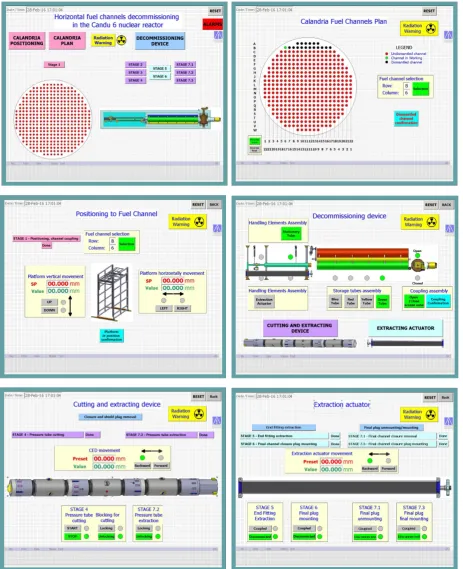
In the Touch Screen HMI operator panel are designed, using specialized software, viewing and operating screens of the decommissioning stages. The operating structure screens are designed on three operating levels: Level 1 - startup main screen, Level 2 - calandria fuel channels plan screen, calandria positioning platform screen and general decommissioning device screen, general alarms screen, Level 3 - removal of the plugs by Cutting and Extraction Device screen, pressure tube cutting end extraction by Cutting and Extraction Device screen and end fitting extracting screen, illustrated in Figure 24.
5.3.1. Operator Panel Level 1 - Start up Screen
Figure 25. Representation of the HMI homepage screen
5.3.2. Operator Panel Level 2 Screens
The Level 2 screens in consists of the following screens: a) The calandria fuel channels plan screen.
In this page the operator performs the following operations (see Figure 26):
selection of the front or rear side of the calandria; selection of the fuel channel to be dismantled; confirmation of the performed operation to preparing
[image:11.595.315.550.79.272.2]the next operation step;
Figure 26. Representation of the calandria fuel channels plan screen
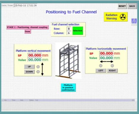
b) The calandria positioning platform screen.
In this page the operator performs the following operations (see Figure 27):
vertical and horizontal movement of the platform device to the fuel channel selected, movement monitored by encoder value.
Figure 27. Representation of the vertical and horizontal movement
c) The general decommissioning device screen.
[image:11.595.313.549.343.529.2]In this page the operator performs the following preliminary operations (see Figure 28):
Figure 28. Representation of the decommissioning device screen
coupling and confirmation of the manual coupling operation finishing (see Figure 29);
Figure 29. Representation of the device coupling steps and the protective cylindrical screen mounting
opening/closing of the device safety valve;
tube selection by turning of storage tubes assembly in the working position
execution element selection by movement of the handling elements assembly in the working position screen selection for working with one of the handling
[image:11.595.58.296.428.624.2] selection of the cutting and extraction device screen for plugs extraction and cutting operations and the extracting actuator screen for end fitting extraction extended channel closure plug mounting (see Figure 30).
Figure 30. Representation of the handling elements selection
d) The general alarms screen
In this screen the operator visualizes and acknowledges the faults appearance when the fuel channel decommissioning operations are performed.
[image:12.595.310.549.286.369.2]The 5 classes of alarms, "Warnings", "Urgent", "High", "Medium" and "Low Errors" are exemplified in Figure 31.
Figure 31. Representation of the alarms classes
5.3.2. Operator Panel Level 3 Screens
The Level 3 screens in consists of the following screens: a) The removal of the plugs by Cutting and Extraction
Device screen.
In this page the operator performs the following operations with the extraction and cutting device (see Figure 32):
Figure 32. Representation of the plugs removal screen
selection of the operation step to be performed; extraction of the channel closure plug from the fuel
channel;
extraction of the shield plug from the fuel channel.
b) The pressure tube cutting end extraction by Cutting and Extraction Device screen.
In this page the operator performs the following operations with the extraction and cutting device:
moving of the extraction and cutting device to the set-point value position;
blocking the extraction and cutting device in the working position;
cutting of the pressure tube in the middle of the pressure tube;
cutting of the pressure tube at the end of the pressure tube at the joint with the end fitting;
extraction of the pressure tube from the fuel channel and storage in the storage tubes assembly;
[image:12.595.56.300.295.366.2] confirmation of each finalization step in order to perform the next operation step (see Figure 33).
Figure 33. Representation of the pressure tube operating confirmation
c) The end fitting extracting screen
In this page the operator performs the following operations with the extracting actuator (see Figure 34):
Figure 34. Representation of the end fitting extraction screen
selection of the operation step to be performed; moving of the extracting actuator to the set-point
value position;
extraction and storage of the end fitting from the fuel channel;
[image:12.595.314.551.447.637.2] [image:12.595.58.295.491.684.2] selection of the operation step to be performed; mounting / removal of the final channel closure plug
to / from the fuel channel (see Figure 35);
Figure 35. Representation of the mounting / removal of the final channel closure plug operating
[image:13.595.61.293.132.186.2] confirmation of each finalization step in order to perform the next operation step (see Figure 36).
Figure 36. Representation of the steps confirmation
5.4. Radiation Level Monitoring Screen
The radiation level monitoring operator panel, mounted on the front of the control cabinet and connected to the radiation sensor, is mandatory for the radiation level monitoring of each extracted components from the fuel channel (see Figure 37). The system performs radiation level measurement, parameters calculation and records in the memory, achieving radiation levels tables for each fuel channel decommissioned component and connecting with a PC for data acquisition.
Based of it is possible to achieve statistics and archiving of these data registered..
Figure 37. Representation of the radiation level monitoring
5.5. Video Displays Monitoring
For monitoring the decommissioning operations of the fuel channel components are required for video cameras for the dismantling steps surveillance performed by the cutting and extraction device, and the extraction actuator (see video captures in Figure 38). The supervision of these operations need three cameras mounted in the following positions:
a video camera in the cutting and extraction device, in front of the extraction module for monitoring the extraction channel closure plug, shield plug and pressure tube;
a video camera in the device for monitoring the extraction of the extended channel closure plug; a video camera in the cutting and extraction device,
[image:13.595.64.298.260.369.2]into the cutting module for monitoring the process of the pressure tube cutting.
Figure 38. Representation of the video display monitoring
6. Conclusions
The design and the configuration characteristics of the fuel channel from the CANDU nuclear reactor are essentially in the design of device components. The fuel channel design has increased margins with extended operating life and is considered a fundamental part in the CANDU system.
The development of the fuel channels have made a significant contribution to the very high capacity factors attained in CANDU reactors because they allow refueling "on-power" status.
The decommissioning of the fuel channels is a complex process which requires the maximum radiation protection degree. The presented device concept could be a safety solution to protect the operators and the environment.
The mechanical design, automation and software programs of the device shall be achieved according to the particular features of the fuel channel components to be dismantled in the nuclear reactor decommissioning program, with respect of all security aspects. All components should be carefully checked accordingly with maintenance rules any deviation needs corrective actions.
The decommissioning of the fuel channels of nuclear reactor is not the final phase of nuclear facility decommissioning. This step represents only decommissioning phase of the calandria structure itself.
[image:13.595.310.549.289.368.2] [image:13.595.61.292.559.721.2]maximum safety against the nuclear radiation during exploitation life. [13] [14] [20] [21] [22]
REFERENCES
[1] Cheadle B.A., Price E.G., “Operating performance of CANDU pressure tubes”, presented at IAEA Techn. Comm. Mtg on the Exchange of Operational Safety Experience of Heavy Water Reactors, Vienna, 1989.
[2] Cheadle, B.A., Price, E.G. Advance in fuel channel technology for CANDU reactors, IAEA Techn. Comm. Mtg on Advances in Heavy Water Reactors, Toronto, 1993;
[3] Chun K. Chow, Hussam F. Khartabil, Conceptual fuel channel designs for CANDU - SCWR, Atomic Energy of Canada Ltd, 2007;
[4] Dirk Peter, Dismantling Techniques, University of Hannover - Institute of Materials Science Waterjet Laboratory, Belgium, 2002;
[5] Laraia Michele, Nuclear decommissioning: Planning, execution and international experience, Woodhead Publishing Limited 2012;
[6] Roger G. Steed, “Nuclear Power in Canada and Beyond”, Ontario, Canada, 2003.
[7] Unsworth G.N. Decommissioning of CANDU Nuclear Power Stations, AECL - 6332, Canada, 1979;
[8] Venkatapathi S., Mehmi A., Wong H., “Pressure tube to end fitting roll expanded joints in CANDU PHWRS”, presented at Int. Conf. on Expanded and Rolled Joint Technology, Toronto, Canada, 1993.
[9] AECB, “Fundamentals of Power Reactors”, Training Center, Canada.
[10]AECL, “CANDU Nuclear Generating Station”, Engineering Company, Canada.
[11]ANSTO, “SAR CH19 Decommissioning”,
RRRP-7225-EBEAN-002-REV0, 2004.
[12]CANDU, “EC6 Enhanced CANDU 6 - Technical Summary”, 1003/05.2012.
[13]CNCAN, “Law no. 111/1996 on the safe deployment, regulation, authorization and control of nuclear activities”, 1996.
[14]CNCAN, “Rules for the decommissioning of objectives and nuclear installations”, 2002.
[15]IAEA, “Assessment and management of ageing of major nuclear power plant components important to safety: CANDU pressure tube”, IAEA-TEDOC-1037, Vienna 1998.
[16]IAEA, “Decommissioning of Nuclear Power Plants and Research Reactors” Safety Standard Series No. WS-G-2.1, Vienna 1999.
[17]IAEA, International Atomic Energy Agency - Design lessons drawn from the decommissioning of Nuclear Facilities, IAEA-TRS-1657, Vienna 2011;
[18]IAEA, “Heavy Water Reactor: Status and Projected Development”, IAEA-TEREP-407, Vienna 1996.
[19]IAEA, “Nuclear Power Plant Design Characteristics, Structure of Power Plant Design Characteristics in the IAEA Power Reactor Information System (PRIS)”, IAEA-TECDOC-1544, Vienna 2007.
[20]IAEA, “Organization and Management for Decommissioning of Nuclear Facilities”, IAEA-TRS-399, Vienna 2000. [21]IAEA, “Selection of Decommissioning Strategy: Issues and
Factors”, IAEA-TECDOC-1478, Vienna 2005.
[22]IAEA, “State of the Art Technology for Decontamination and Dismantling of Nuclear Facilities”, IAEA-TRS-395, Vienna 1999.
[23]IAEA, “Water channel reactor fuels and fuel channels: Design, performance, research and development”, IAEA-TEDOC-997, Vienna 1996.
[24]Nuclearelectrica SA, “Cernavoda NPP Unit 1&2, Safety features of Candu 6 design and stress test summary report”, 2012.