© 2016, IRJET | Impact Factor value: 4.45 | ISO 9001:2008 Certified Journal | Page 1285
Automation of Bottle Filling System in Industries
using PLC AND SCADA
TARUN PRATAP SINGH
1, SHIVAM SINGH
2, VIPUL MAURYA
3, Asst. Prof. P.SURESH
4123 M.TECH SCHOLAR, Dept. of mechanical Engineering, GALGOTIAS UNIVERSITY, NOIDA, INDIA 4 ASST. PROFESSOR, Dept. of mechanical Engineering, GALGOTIAS UNIVERSITY, NOIDA, INDIA
---***---Abstract-This paper gives information to build a miniature of bottling plant. To accomplish this PLC and SCADA have been used. A programmable logic controller (PLC) or programmable controller is a digital computer used for automation of electromechanical processes, such as control of machinery on factory assembly lines [1]. Supervisory control and data acquisition refers to centralized systems which monitor and control entire sites. A variable-frequency drive (VFD) is used for controlling the speed of electric motor by controlling the frequency of the electrical power supplies to the motor. A fully automates bottling plant was made and the required efforts to achieve high efficiency and energy saving along with speed control were achieved [2].
Keywords: PLC, SCADA, Automation etc.
1. Introduction
This project deals with the controlling of bottle filling system speed and monitor with more efficiency, quality and quantity of production and provide more flexibility to the system or plant. Earlier in this system use the electromechanical relay for this purpose but the drawback of this is complicated design, less flexibility, low quality and not fully automated. And controlling of plant is very tough. But now we use PLC for give automation to the machine and SCADA use for controlling and monitoring the whole process. In many industries this is necessary to achieve their goal. For example if any industry which have production rate 20 bottle per minute but demand of their production suddenly increase to 100 bottle per minute than want to increase their productivity so can be easily develop the program for PLC and achieve goal immediately without changing hardware.
2. Proposed device
Now compare systems manual, semiautomatic and full automatic this is done by using changing quantity of the product while process running. While the process running this is monitor by using SCADA and provide display view for the changing the input configuration
first change or make the program for PLC and upload that on PLC and also change the value of SCADA after updating program achieve the desired output.
2.1 Hardware part
The hardware used for bottle filling system are PLC(siemens-200), sensors (Proximity), control valve(solenoid valve), Actuators, power supply +24v, VFD(variable frequency drive), communication cable PPI-USB, communication with pc cable (rs-232), conveyers.
Fig1. Hardware configuration
2.2 Programmable logic controller (PLC)
© 2016, IRJET | Impact Factor value: 4.45 | ISO 9001:2008 Certified Journal | Page 1286 diagrams. Thus, an industrial electrician or electrical
engineer accustomed to reading ladder logic schematics would feel comfortable programming a PLC to perform the same control functions.
2.3 Actuators
Most industrial processes require objects or substances to be moved from one location to another, or a force to be applied to hold, shape or compress a product. Such activities are performed by Prime Movers; the workhorses of manufacturing industries. In many locations all prime movers are electrical. Rotary motions can be provided by simple motors, and linear motion can be obtained from rotary motion by devices such as screw jacks or rack and pinions. Where a pure force or a short linear stroke is required a solenoid may be used (although there are limits to the force that can be obtained by this means). Electrical devices are not however, the only means of providing prime movers. Enclosed fluids (both liquids and gases) can also be used to convey energy from one location to another and, consequently, to produce rotary or linear motion or apply a force. Fluid based systems using liquids as transmission media are called hydraulic systems. Gas-based systems are called Pneumatic systems. The most common gas is simply compressed air. Although nitrogen is occasionally used
2.4 Variable Frequency Drive (VFD)
The Variable frequency drive is used to control the speed, torque and direction of the motor. Features of the VFD given below-
Power Ratings
Ambient temperatures up to 50 °C permitted with minimal spacing between drives
Internal RS-485 communications for communication with peripherals
Drive overload protection, ramp regulation, and flying start
Configuration and programming via integral LCD keypad, Drive Tool software
Changing the direction of the motor without changing the wiring
Control starting torque which remove vibration.
2.5Solenoid valve
It is an electromagnetic valve used to control various types of liquids by opening and closing automatically. Various types of applications are performed by using
this solenoid valve. This use orifice plate to control the flow of the liquid, we use this because this is cheaper than other.
3. Software Part
In this part we are going to discuss about the software which are used for programming and controlling there are several software for programming this depend on PLC. Some of them given below,
Every PLC has associated programming software that allows the user to enter a program into the PLC. Software used today is window based and can be run on PC. And for the supervision of the control use SCADA (supervisory control and data acquisition)
which control whole the process remotely for this purpose use INTOUCH WONDERWARE software which work with any type of PLC.
Table1: Software used with different PLC
PLC branding name
Software use for programming
1. DELTA PLC WPL SOFT.
2. MITSUBHISHI PLC GX-DEVELOPER
3. SIEMENS MICRO WIN STEP7
4. ALLEN BREADLY RS-LOGIC MICRO-500
4. Ladder logic
Ladder logic is programming language used to write the PLC program. The ladder view of the program is given below for filling station[2]
In ladder logic use the digital Boolean language for programming e.g. when the switch is open than use normally open (NO) switch when switch is closed than use NC (normally closed) switch and provide timing use timer which is inbuilt into the PLC just give instruction TMR similarly for counter. Ladder diagram build between positive and negative power supply this is called rung. Rung is nothing but this is program which gives the relation between input and outputs or can say run the output according to inputs,
© 2016, IRJET | Impact Factor value: 4.45 | ISO 9001:2008 Certified Journal | Page 1287 Click on “Main Routine” and you should see this. The
[image:3.595.36.283.134.240.2]programming shown below
Fig 2 .Software of PLC
5. Selection of plc and sensors
Selection of PLC depends upon the input and outputs when we have large number of input and outputs than use rack PLC or modular PLC
otherwise use non-modular PLC which have limited no. of input and outputs. And selection of PLC also depend on memory size, system speed and
communication of PLC with other device. In the proposed device simens-200 is used. In simens-200, there are 8 inputs and 6 relay type outputs. 4 ms full programs scanning time and memory is enough for the automatic bottle filling. So it is chosen[8]
6.Connection of plc with input and output
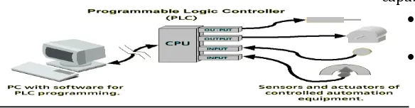
Fig 3.connection of PLC with computer and device This fig show that how connect the plc to inputs (e.g. sensors, switch etc.) and outputs (motors, actuators etc.).
Fig4. Software and Hardware view for PLC connection
Inputs port of the PLC are connected shrink mode means inputs are directly connected to power supply and between the PLC and inputs there are switches till the button is not pressed than PLC is not connected to the inputs. But output ports of the PLC is connected in source type means +24v power supply are connected to all outputs but this is not connected to -24v power supply this is connected by using the ladder program which provide connection between inputs and outputs.
Ethernet port provides Web server capability, email capability and protocol support
Built-in LCD with backlight lets you view controller and I/O status
Built-in LCD provides simple interface for messages, bit/integer monitoring and manipulation
Expands application capabilities through support for as many as seven 1762 Micro Logix500 Expansion I/O modules with 256 discrete I/O
As many as six embedded 100 kHz high-speed counters (only on controllers with DC inputs)
[image:3.595.40.332.448.524.2]© 2016, IRJET | Impact Factor value: 4.45 | ISO 9001:2008 Certified Journal | Page 1288
7. Prototype design of PLC based automatic bottle filling station
Fig5 .Practical View on SCADA System
7.1. Speed control
We can control the speed of the whole system by using variable frequency drive and by changing program also. VFD control the speed and direction of the motor which directly connected to the conveyer system of the process so this speed up according to requirement and this also be done by changing program of PLC in program just change the value of the timer to speed up the process.[3]
7.2. System specification
1. Input: 24 V DC
2. Capacity: 15-200 BPM
3. Maximum bottle height: 6.6’’
4. Maximum bottle diameter: 4.6’’
5. Maximum pressure: 200 Pascal
6. 1 filling Nozzle
7. Automatic shut off when bottle is full
8. Best liquid: Water or any other liquid
8. Results
The device can fill up to 20-100 bottles of maximum height of 6.6’’ and maximum bottle diameter of 4.6” in 1 minute. There is no need of any external pumps and various types of sensors are used. It is a time based control and use flow sensors to check the flow of liquid and this fill the bottle as per norms which can’t done by human without measuring instrument. So the practical research result is much satisfactory. It also
helps to understand the necessity of PLC in industrial automation and also to realize the necessity of studying it.
Table2: Time requirement between manual and automation method
task Manually
operate d
Proposed method
Bottle fading 5 sec 0.6sec – 3sec
Filling time 7 sec 0.6sec -1sec
Checking/inspe
ction 5sec 0.2sec
capping 6sec 0.3sec
labeling 8sec Less than 1 sec
Table3: Manpower requirement between manual and automation method
Task Manually
operated
Proposed method
Bottle fading 1 1
Load filling More than 2 0
Checking/inspection 1 0
Capping 2 0
Labeling 2 0
9. Conclusion
Automation system are used to increase productivity, better quality in less time. The main purpose of this whole system is control the plant without human this provide full automation to any industry by using PLC and SCADA. This system is more flexible than other, more reliable time saving and user friendly.
REFERENCES
© 2016, IRJET | Impact Factor value: 4.45 | ISO 9001:2008 Certified Journal | Page 1289
Journal of Emerging Technology and Advanced Engineering (ISSN 2250-2459)2012.
[2] 1 SavitaM.tech,R.N College of Engineering & Management,Rohtak,India.2 Lokeshwar Assistant Prof, R.N College of Engineering&management,Rohtak,India
“Implementation and performance analysis of bottle filling plant using ladder language”.
International Journal of Science and Research (ISSN 2319-7064) 2012.
[3] 1 Ahmed Ullah AbuSaeed,2 Md.Al- Mamun,3 A.H.M.ZadidulKarim, Department of EEE, University of Pacific,Dhanmondi,Dhaka. “Industrial Application of PLCs In Bangaladesh” International Journal of Scientific & Engineering Research (ISSN 2229-5518)2012.
[4] 1Mallaradhya H M, 2 K R Prakash1Department of Industrial Automation Engineering, VTU-RO, Mysore, Karnataka, India. 2Department of Mechanical Engineering, National Institute of Engineering, Mysore, Karnataka, India “Automatic liquid filling to bottles of different height using programmable logic controller”.International Journal of Mechanical and Production Engineering, ISSN: 2320-2092, Oct-2013.
[5] Joanna Marie M. Baroro, Melchizedek I. Alipio, Michael Lawrence T. Huang, Teodoro M. Ricamara, Angelo A. Beltran Jr. School of Graduate Studies, Mapua Institute of Technology, Philippines “Automation of Packaging and Material Handling Using Programmable Logic Controller”,.International Journal of Scientific Engineering and Technology(ISSN: 2277 – 1581) June 2014.
[6] D.Ahuja1, N.Chaudhary 2 Department of Electrical and Electronics Engineering, YMCA University of Science and Technology, Faridabad, 121006, India.