International Journal of Emerging Technology and Advanced Engineering
Website: www.ijetae.com (ISSN 2250-2459,ISO 9001:2008 Certified Journal, Volume 4, Issue 3, March 2014)
Normalized Dynamic Simulation of 3-phase Induction Motor
using MATLAB/SIMULINK
Abhinav
1, Venu Sangwan
2
Electrical department, PEC University of technology Chandigarh-160012, India
Abstract— Power system engineers and design engineers
use normalized values for the variables. This paper presents dynamic modeling and simulation of 3-phase induction motor using dq0 axis transformation of normalized stator and rotor variables in the synchronous reference frame assisted by MATLAB/SIMULINK. For this purpose, the relevant electrical differential equations and mechanical differential equation, known by electrical machine researchers, are stated at the beginning and then generalized model in synchronous reference frames of 3-phase induction motor is developed and implemented by using MATLAB/SIMULINK.
Keywords—MATLAB/SIMULINK, induction motor,
normalized value, dynamic modeling, dq0 model.
I. INTRODUCTION
Induction motors are called as horsepower of industry. According to a survey, 75% of motors used in industries are induction motors due to their high torque to volume ratio, ruggedness, robustness & low maintenance. The analysis of induction motor is carried out in steady state whereby the machine is modelled as a second order electromechanical system. However for in depth analysis, dynamic behaviour is accounted whereby machine dynamics are of fifth order [1].
The dynamic model considers the instantaneous effects of varying voltages/currents, stator frequency, and torque disturbance. The dynamic model of the induction motor is derived by transferring the three-phase quantities into two phase direct and quadrature axes qualities. The equivalence between the three phase machine models is derived from the concept of power invariance [2]. This approach is desirable because of conceptual simplicity obtained with two sets of winding, one on the stator and the other on the rotor.
The following assumptions are made to derive the dynamics model [3]:
i. Uniform air gap;
ii. Balanced rotor and stator windings, with
sinusoidally distributed mmf;
iii. Inductances vs. rotor position is sinusoidal; and
iv. Saturation and parameter changes are neglected
d-q model is extensively used in control application as it has capability to convert sinusoidal variables quantities to dc quantities using suitable reference theory. By having the voltage and current quantities in dq frame, it is possible to control the speed of the machine by controlling the flux and torque independently. It is also
Simulink is a useful tool for understanding the performance, analysis & design of such machines. Simulink induction machine models are available in literature [5]-[6], but they appear to be black boxes with no internal details. Reference [7]-[8] refers to implementation of dynamic model and simulink of induction motor in synchronously rotating reference frame. But, fail in explain the performance of model with normalized variables.
In this paper, MATLAB/SIMULINK is used to simulate the dynamic performance of an induction motor model whose normalized stator and rotor variables are referred to a synchronous reference frame.
II. SYSTEM MODELING
Usually, when an electrical machine is simulated in circuit simulator like PSpice, its steady state model is used; this implies that all transients are neglected during load changes and stator frequency variations, but for electrical drive studies, the transients behaviors is also important.
In the past, researchers have developed their own software packages for dynamics modeling of induction motor. In [9], a software package was developed, using the FORTRAN programming language, for the steady state and dynamic simulation of induction motor drives. It is unnecessary to develop user-written software for dynamic model of induction motor when you have
proprietary software package such as
MATLAB/SIMULINK, licensed by MathWorks.
MATLAB/SIMULINK makes simulation design more efficient and allows other interested parties to understand the operation of the system more easily than a programming-language implementation.
MATLAB provides a powerful matrix environment, the basis of state-space modeling of dynamic systems, for system design, modeling, and algorithm development. SIMULINK is an extension to MATLAB and allows graphical block diagram modeling and simulation of dynamic systems [10].
The dynamic d-q model is developed using MATLAB and a simulation is carried out to observe the speed flux, torque and current waveforms.
III. DQMODELING
International Journal of Emerging Technology and Advanced Engineering
Website: www.ijetae.com (ISSN 2250-2459,ISO 9001:2008 Certified Journal, Volume 4, Issue 3, March 2014)
A. Nomencuture
d : direct axis q : quadrature axis
s : stator variables r : rotor variables
n : normalized value
Pb : normalized power
Vb
vasn, vbsn, vcsn : normalized input voltage for phase a, b
and c
vqsn, vdsn : normalized stator q and d axis voltages
vqrn, vdrn : normalized rotor q and d axis voltages
iqsn,idsn : normalized stator q and d axis current
iqrn, idrn : normalized rotor q and d axis current
Ψqsn, Ψdsn : normalized stator q and d axis modified
flux linkages
Ψqrn, Ψdrn : normalized rotor q and d axis modified
flux linkages ωb : base speed
ωrn : normalized rotor speed
ωcn : normalized angular speed in
synchronous reference frame Ten : normalized electromagnetic torque
Tln : normalized load torque
Rsn : normalized stator resistance
Rrn : normalized rotor resistance
Xsn : normalized stator reactance
Xrn : normalized rotor reactance
Xmn : normalized magnetizing reactance
J : moment of interia H : interia constant P : number of poles
B. Equations
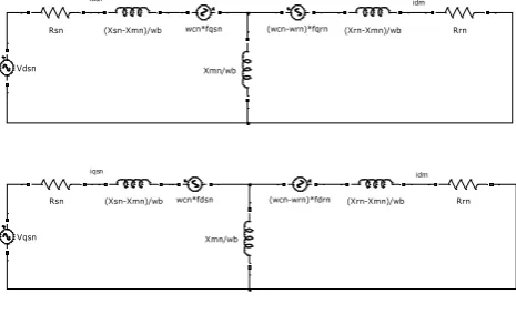
[image:2.595.53.286.601.742.2]Driving the model equations can be generated from the dq0 equivalent circuit of the induction machine shown in figure 1.
Figure 1: The d-q normalized equivalent circuit of an Induction Motor
In a generalize d-q reference frame, the electrical equation in normalized form of squirrel induction motor can be found as follows:
(1)
(2)
(3)
4)
For squirrel induction motor as in the case of this paper and in equation (3) and (4) are set to zero since rotor cage bars are short circuited. Modified flux linkages in normalized form are: (5)
(6)
(7)
(8)
Normalized electromagnetic torque equation in terms of normalized modified flux linkage and normalized current form: ( ) (9)
Based on the above equations, normalized rotor speed can be determined as follows:
Where
⁄
After driving the torque and speed equations in term of d-q flux linkages and currents of the stator, the d-q axis transformation should now be applied to the machine input (stator) voltages.
The three-phase stator voltages of an induction machine under balanced conditions can be expressed as:
√
√ (
)
√ (
)
idsn idrn
wcn*fqsn
Xmn/wb Vdsn
Rsn (Xsn-Xmn)/wb (wcn-wrn)*fqrn (Xrn-Xmn)/wb Rrn
iqsn idrn
wcn*fdsn
Xmn/wb Vqsn
International Journal of Emerging Technology and Advanced Engineering
Website: www.ijetae.com (ISSN 2250-2459,ISO 9001:2008 Certified Journal, Volume 4, Issue 3, March 2014)
These three-phase voltages are transferred to a synchronously rotating reference frame in only two phases (d-q axis transformation). This can be done using the following two equations.
[ ] [
⁄ ⁄ √ ⁄ √ ⁄ ⁄ ⁄ ⁄
] [ ]
Then, the direct and quadrature axes voltages are:
[ ] [ ] [ ]
The instantaneous values of the stator and rotor currents in three-phase system are ultimately calculated using the following transformation:
[ ] [ ] [ ] [ ] [ ⁄ ⁄ √ ⁄ ⁄ ⁄ √ ⁄ ⁄ ] [ ]
IV. MATLAB/SIMULINK IMPLEMENTATION
The inputs of an induction machine are three phase voltages, their fundamental frequency and the load torque. The outputs of an induction machine are three-phase currents, electrical torque, and rotor speed.
[image:3.595.58.278.186.283.2]Dynamic model of squirrel cage induction motor is developed by using the equations from (1) – (18) in MATLAB/SIMULINK platform in figure 2.
Figure 2: The 3-phase Induction Motor Matlab/Simulink Model
In this model the simulation starts with generating a three-phase stator voltages according to the equations (12, 13, 14), and then transforming these balanced voltages to two phase voltages referred to the synchronously rotating frame using Clarke and Park transformation as in equations (15, 16)
[image:3.595.324.557.192.321.2]Figure 3 illustrates the internal structure of the induction machine d-q model, implemented according to equations (1-11), through which the flux linkages, currents, torque and the rotor angular speed are calculated.
Figure 3: The internal structure of the 3-phase Induction Motor d-q model
Figures 3 & 4 show the implementation of torque Ten
and angular speed ωrn as expressed in equations (9), (10)
[image:3.595.349.493.409.476.2]respectively.
Figure 4: The implementation of the torque equation Ten
Figure 5: The implementation of the angular speed equation (wrn)
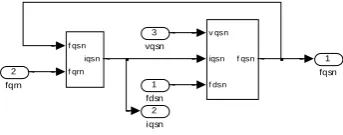
The Matlab/Simulink models to find the flux linkages fqsn, fdsn, fqrn, fdrn are shown below:
Figure 6: Block for flux linkage fqsn
[image:3.595.53.279.531.660.2] [image:3.595.343.515.656.723.2]International Journal of Emerging Technology and Advanced Engineering
Website: www.ijetae.com (ISSN 2250-2459,ISO 9001:2008 Certified Journal, Volume 4, Issue 3, March 2014)
Figure 7: Block for flux linkage fdsn
Figure 8: Block for flux linkage fqrn
Figure 9: Block for flux linkage fdrn
The Matlab/Simulink models to show the internal structure of the blocks shown above for implementation of the flux linkages fqsn, fdsn, fqrn, fdrn as stated in equation (1-4) are shown below:
Figure 10: Internal structure of block of flux linkage fqsn
Figure 11: Internal structure of block of flux linkage fdsn
Figure 12: Internal structure of block of flux linkage fqrn
Figure 13: Internal structure of block of flux linkage fdrn
The Matlab/Simulink models to show the internal structure of the blocks shown above for calculation of the currents iqsn, idsn, iqrn, idrn as stated in equation (5-8) are shown below:
Figure 14: Internal structure of block of current iqsn
Figure 15: Internal structure of block of current idsn
Figure 16: Internal structure of block of current iqrn
Figure 17: Internal structure of block of current idrn
V. MATLAB/SIMULINK RESULTS
The simulations are carried out using the motor data obtained from no-load test, short circuit test, retardation test and stator resistance measurement test on the motors.
2 idsn
1 fdsn v dsn
idsn
f qsn f dsn f dsn
f drn idsn
3 fqsn 2
fdrn
1 vdsn
2 iqrn
1 fqrn v qrn
iqrn
f drn
wrn f qrn f qrn
f qsn iqrn
4 wrn
3 fdrn
2 vqrn
1 fqsn
2 idrn
1 fdrn v drn
idrn
f qrn
wrn f drn f drn
f dsn idrn
4 fqrn
3 wrn
2 vdrn
1 fdsn
1 fqsn 1
s
rsn wb
wcn Constant
3 fdsn
2 i qsn
1 vqsn
1 fdsn 1
s
rsn wb
wcn Constant
3 fqsn
2 i dsn
1 vdsn
1 fqrn 1 s
rrn wb
wcn Constant
4 wrn
3 fdrn
2 iqrn 1 vqrn
1 fdrn 1 s
rrn wb
wcn Constant
4 wrn
3 fqrn
2 idrn 1 vdrn
1 iqsn xmn
xrn
1/(xrn*xsn-xmn*xmn)
2 fqrn
1 fqsn
1 idsn xmn
xrn
1/(xrn*xsn-xmn*xmn)
2 fdrn
1 fdsn
1 iqrn xmn
xsn
1/(xrn*xsn-xmn*xmn)
2 fqsn
1 fqrn
1 idrn xmn
xsn
1/(xrn*xsn-xmn*xmn)
2 fdsn
International Journal of Emerging Technology and Advanced Engineering
Website: www.ijetae.com (ISSN 2250-2459,ISO 9001:2008 Certified Journal, Volume 4, Issue 3, March 2014)
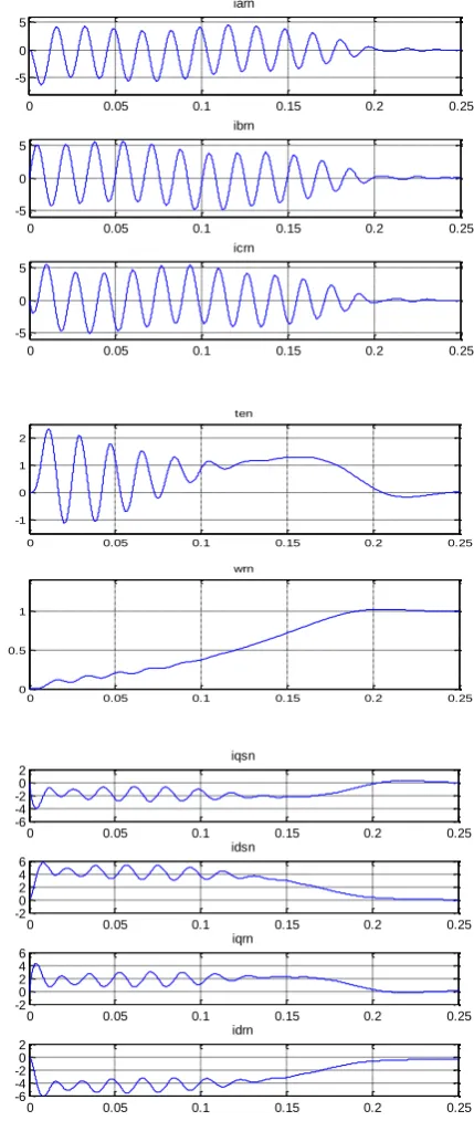
40hp 60hz 3-phase induction motor has the following ratings and parameters:-
Rs=0.22Ω Rr=0.209Ω
Lm=0.04H Ls=0.0425H Lr=0.043H B=0 Load torque= 0 J=.124kg-m2
[image:5.595.335.550.146.654.2]The results of the simulation are given for the induction motor with the following specifications:
Figure 18: Machine variables during free acceleration of a 40-hp induction motor
0 0.05 0.1 0.15 0.2 0.25
-0.5 0 0.5 1
fdsn
0 0.05 0.1 0.15 0.2 0.25
-0.4 -0.20 0.2
fdrn
0 0.05 0.1 0.15 0.2 0.25
-1.5 -1 -0.5 0
fqrn
0 0.05 0.1 0.15 0.2 0.25
-1 -0.5 0 0.5
fqsn
0 0.05 0.1 0.15 0.2 0.25
-5 0 5
iasn
0 0.05 0.1 0.15 0.2 0.25
-5 0 5
ibsn
0 0.05 0.1 0.15 0.2 0.25
-5 0 5
icsn
0 0.05 0.1 0.15 0.2 0.25
-5 0 5
iarn
0 0.05 0.1 0.15 0.2 0.25
-5 0 5
ibrn
0 0.05 0.1 0.15 0.2 0.25
-5 0 5
icrn
0 0.05 0.1 0.15 0.2 0.25
-1 0 1 2
ten
0 0.05 0.1 0.15 0.2 0.25
0 0.5 1
wrn
0 0.05 0.1 0.15 0.2 0.25
-6 -4 -2 0 2
iqsn
0 0.05 0.1 0.15 0.2 0.25
-2 0 2 4 6
idsn
0 0.05 0.1 0.15 0.2 0.25
-2 0 2 4 6
iqrn
0 0.05 0.1 0.15 0.2 0.25
-6 -4 -2 0 2
International Journal of Emerging Technology and Advanced Engineering
Website: www.ijetae.com (ISSN 2250-2459,ISO 9001:2008 Certified Journal, Volume 4, Issue 3, March 2014)
Finally, the machine parameters should be defined to the simulated machine system in order to complete the simulation process using graphical user interface (GUI) available in Matlab/Simulink. Figure 19 shows the GUI of the induction motor model shown earlier in figure 2.
VI. CONCLUSIONS
In this paper, an implementation and dynamic modeling of a three-phase induction motor using Matlab/Simulink are presented in a step-by-step manner. The model was tested by 40 hp 60hz 3-phase induction motors. The simulated machines have given a satisfactory response in terms of the torque and speed characteristics.
This concludes that the Matlab/Simulink is a reliable and sophisticated way to analyze and predict the behavior of induction motors using the theory of reference frames.
REFERENCES
[1] Andrzej M. Trynadlowski, “Control of induction motor” Academic Press: England, 2001.
[2] P. C. Sen, “Princibles of Electric Machines and power electronics”, Wily, 2nd edition, 1996.
[3] R. Krishnan, “Electrical Motor Drives: modeling, analysis and control”, PHI
[4] Sushma, P. ; Samaga, B.L.R. ; Vittal, K.P. “DQ Modeling of
Induction Motor for Virtual Flux Measurement” IPEC, 2010 Conference Proceedings , 2010 , pp. 903 – 908
[5] A Dumitrescu, D.Fodor, T.Jokinen, M.Rosu, and S.Bucurencio,
"Modeling and Simulation of electric drive system using Matlab/Simulink environments," international Conference on Electric Machines & Drives (JEMD), 1999, pp.451-453.
[6] M.L.de Aguiar, and M.M.Cad, "The concept of complex transfer
functions applied to the modeling of induction motors," Power Engineering Society Winter Meeting, 2000, voU, pp.387-39I.
[7] Adel Aktaibi & Daw Ghanim,“Dynamic Simulation of a
Three-Phase Induction Motor Using Matlab Simulink,”
[8] Burak Ozpineci and Leon M. Tolbert, "Simulink implementation
of induction machine model - a modular approach," international Conference on Electric Machines & Drives (JEMD), 2003, vol.2, pp.728-734.
[9] J. D. Lavers and R. W. Y. Cheung, “A software package for the
steady state and dynamic simulation of induction motor drives,” IEEE Trans..
[10] Wade, S. ; Dunnigan, M.W. ; Williams, B.W. “Modeling and
simulation of induction machine vector control with rotor
resistance identification,” ,Power Electronics, IEEE Transactions,