ISSN: 1992-8645 www.jatit.org E-ISSN: 1817-3195
210
FPGA IMPLEMENTATION OF MIMO METAHEURISTIC
MAXIMUM-LIKELIHOOD ALGORITHM HISD-ML
1,2ABDESSALEM TRIMECHE, 2,3ANIS SAKLY, 1,2ABDELLATIF MTIBAA
1
Research Unit: Laboratory of Electronic and Microelectronic, University of Monastir, Tunisia.
2
National Engineering School of Monastir, University of Monastir, Tunisia.
3
Research Unit: Industrial Systems Study and Renewable Energy (ESIER) University of Monastir, Tunisia.,
E-mail: 1,[email protected] , 2,[email protected] , 1,[email protected] ,
ABSTRACT
In many wireless communication systems, the detection comes down to solving an optimization problem of a combinatorial system of the form y = Hx + w. In the general case, it’s known that ML is "NP-Hard". In this paper, to solve this problem, a new algorithm called HISD suboptimal (hyperplane Intersection and Selection Detector) is proposed. This algorithm is based on a geometric approach. Compared with existing algorithms, the HISD has three very attractive features for implantation into real systems. The first relates to its performance in terms of BER which are close the optimum (ML) limit. Its complexity in terms of calculation is small and its structure is inherently parallel, which makes its hardware implementation easier. The puropose of our research is to develop a near optimal detector that performs a similar performance ML with a polynomial computational complexity. Indeed, we adopt an approach based on the methods of operational research in real time and especially meta-heuristics. Indeed, the developed method is composed of two complementary techniques: the intensification and diversification .In this paper, we propose a hardware implementation of the HISD algorithm in FPGA for MIMO (Multiple Input Multiple Output) systems.
Keywords: MIMO, HISD, FPGA, ML, BER, SNR…
1. INTRODUCTION
The increase in spectral efficiency remains one
of the major challenges of digital wireless communication. MIMO systems transmissions constitute a solution to improve the transmission quality on difficult channels.
In recent years, an important trend in the metaheuristic field is that of integrating different components resulting in successful hybrid methods that attempt to better exploit the specific problem structure [1]. As a direct consequence of this, sometimes it is not clear how to name a specific heuristic as it uses ideas from several methods. In this regard, the first objective of our research is to develop a quasi-optimal detector
near ML performance with polynomial
computational complexity. It is important to know that in practice many modern meta-heuristic techniques provide high quality solutions, especially for ML detection problems as shown in [2].
The maximum likelihood ML detector has better performance in terms of bit error rate compared to other existing detectors but unfortunately it has exponential computational complexity [3]. Indeed, we adopt an approach based on the methods of operational research in real time and especially meta-heuristics. Indeed, the developed method is composed of two complementary
techniques: the intensification and
diversification. Intensification is a neighborhood search method. It is used to find the right solution to the detection problem, this technique has a weakness: it can be trapped in a very small local optimum. To overcome this weakness, effective diversification technique was required. Diversification is used to create a sub starting set which includes the right solutions to reduce the risk that the intensifying stage gives local minimum for all starting solutions. When transmitting with a MIMO system (Multiple
ISSN: 1992-8645 www.jatit.org E-ISSN: 1817-3195
211 transmitted is reached if emits each time a different symbol on each antenna. The number of symbols transmitted simultaneously is equal to the number N of transmitting antenna; it will be represented in the rest of the article by the vector of the baseband signal
x
ˆ
. Our studies present a new meta-heuristic method with quasi-optimal performance, limited complexity and affluent properties for hardware implementation (highly parallel structure). This paper describes the detection algorithm based on the meta-heuristicapproach to detect the transmitted signal x ∈ ξ =
{-1, 1}n of y = Hx + W, knowing the received
vector y when y ∈ Rm and the channel matrix H
∈ Rmxn. The algorithm has been specifically
tailored to run on platforms (FPGA) with minimal computational hardware [4].
We start by describe the HISD approach, we explain in the second time the diversisification and intensisification phases. Thirdly, we present a compariasion between fifferents detectors studied: ML; ZF; MMSE and our HISD detector algorithm. In second step, we studied the complexity of each detector.
In this paper, a pipelined architecture for hardware HISD implementation is presented. Benchmark functions solved by FPGA hardware HISD implementations are compared with ML, ZF and MMSE detectors implementation. We start presenting the symbol detection in MIMO system using HISD method, in second time a FPGA implementation of HISD detectors for MIMO systems description will be detailed. Thirdly, a comparison of different detectors FPGA implementation must be elaborate. Finally, we discuss the performance results of FPGA based HISD implementation
2. HISD DESCRIPTION ALGORITHM
New techniques that advertise a more efficient use of spectrum have been proposed. Among these techniques we find transmissions Ultra Wide Band (UWB) transmissions or millimeter
frequencies. Alongside these approaches,
wireless telecommunication systems called MIMO (Multiple Input Multiple Output), are also contemplated. These systems are considered as a solution for improving the transmission quality on difficult channels. The MIMO transmission system with multiple antennas for transmission and reception is considered a very good candidate in many standards organizations. MIMO technology effectively meets the needs of future wireless communication networks as it
allows increasing throughput while allowing a longer range
The HISD algorithm is one of sub-optimal methods like ML (Maximum Likelihood) which are developed to reduce the size ξ set of solutions selecting a ξ start subset of points.
The HISD algorithm is a new ξ start selection
method.
It is about finding solutions near to the optimal solution using a geometric approach taken particularly original works of H. Artes, D. and F. Seethaler Hawatsch [5].
The HISD use an improvement of this approach associated with a process of optimization methodology that contains two complementary strategies [6]. The methodological approach HISD is to see the resolution of the decoding problem as a problem of Operational Research. Therefore, this algorithm consists of two phases, namely "intensification" and "diversification". Improved geometric approach concerns the possibility of calculating with real elements rather than complex, which greatly facilitated
implementation of the algorithm. The
diversification phase is to seek ξ start all likely
reach points in the intensification phase at the point corresponding to the optimum solution. The HIS algorithm uses two parameters that are managed in the diversification phase. The first D is the number of singular vectors obtained from the decomposition of the channel matrix H and
the second C is the number of elements of ξ start
candidate’s intensification phase [7].
3. DIVERSIFICATION PHASE
The diversification phase should allow around
the optimal point to find ξ start candidate’s points.
Those must be the least redundant as possible to cover a sufficient area containing the optimal point and the intensification phase eliminates the trap of local minima.
Let's suppose that the subset
π
1⊂
ζ
contains allstarting points leading to the solution ML: x
∈
Π1 xML=greedy (x).T he function greedy () is
the iterative function of intensification and Π is the set of points which converge to the optimal solution in the intensification phase.
The stage of diversification must give a subset
therefore
ζ
start who verifiesζ
start∩
π
1≠ ∅
.A geometric approach leads us to an efficient
method to find
ζ
start . In first time, we try to findISSN: 1992-8645 www.jatit.org E-ISSN: 1817-3195
212 MMSE. Thereafter, the decomposition in singular value of the channel matrix H = UQVT is used knowing that the matrix diagonal Q contains the singular values
{λ
k}
k=1...n and thematrixes unit U and V contain, respectively, the singular vectors
{u
k}
k=1...m{v
k}
k=1...n.We suppose that
λ
k are classified in theincreasing order (
λ
1λ
2..
λ
n ). Let’snote
ρ
ZF= H
+y
the solution under optimalgenerated by the ZF detector. For each point
x
∈
ξ
, x –
ρ
ZFis a vector from Rn expressed inthe V basis like
x –
ρ
ZF=
n
k k=1
k
v
α
∑
where αkare real coefficients. We can express the value of the function cost (objective function) to a feasible point:
2 2
( )
(
ZFf x
=
y
−
Hx
=
H x
−
ρ
(1)
We define
Δ
k= {z
∈
R
n/ z =
ZF+ γv
k,
γ
∈
R}
like a straight in Rn passing by the pointZFand having like direction the vector singular
vk. The idea of the diversification phase is to
choose the feasible points close to the straight
Δ
1,.. , Δ
D to create a subsetζ
startcontaining thegood starting points. We define ξ = {-3,+3}n
Geometrically, this subset includes the apex of the hypercube unit of n dimension. The essential idea of this method is to find the points of
intersection between
Δ
k and the faces of thehypercube unit. For a straight
Δ
k there are more4n feasible points Ik ϲ {-3,+3}n who represent the
projection on {-3,+3}n of all intersection points
between
Δ
k define the following manner: P(i,s)= {z
∈
Rn / z(i) = s } , shown in figure1.
I.
:
Figure .1: The first stages of diversification
Let's examine the intersection between
Δ
k andthe hyperplan P(i,s) = {z
∈
Rn / z(i) = s }.We obtain:ZF (i)
+
γ
,v
k(i)= s
This intersection includes two cases:
If
v
k(i) ≠0
γ
,=
then the
generated point is
β
,=
γ
,v
k+
ZF, Thereturned point is
β
,,
If vk(i) = 0 le pointretourné
β
, =x
. SoI
k= {
β
, ….,contains to the more 4n distinct feasible points. The subset of beginning of the intensification
stage is defined by
ξ
start=
∪
ξ
k where ξk⊂
I
k contains the best C dawned of Ik. Wecontend that repair diversification is useful in various practical situations [8].
4. INTENSIFICATION PHASE
For each step K the best solution xk+1 is chosen
in the neighborhood NQ(xk) of the solution xk.
The neighborhood of xk is a subset of
ψ
and canbe defined of the following manner: The Q
neighborhood of a point x0
∈
ψ
is the subsetN
Q(x
0) = {x, d
H(x, x
0)
Q} where d
H(.)
is the hamming distance. For each x
∈
NQ(x0),x0 and x defer themselves by in the more Q
composing. . The total number of vectors in
N
Q(x
0) est | N
Q(x
0)| =
∑ !ni$
% . The greedymethods give a solution to f(xk) f(x) x
∈
NQ(xk). As shown in the fig 2, Q = 1 defines the
points bound to x0 by a side of a cube of n
ISSN: 1992-8645 www.jatit.org E-ISSN: 1817-3195
213 We intend to achieve an appropriate trade-off between intensification and diversification with the aim of being able to effectively sample the solution space, which is a basic principle for designing efficient metaheuristics [10].
[image:4.612.92.289.186.277.2]Q=1 Q=2
Figure. 2: Representation of the neighborhood of the x point for Q = 1 and 2
5. DESCRIPTION OF HISD ALGORITHM
The HISD algorithm depends on two parameters that D are the number of clean vectors and C that represent the number of the best candidates. A hardware component is defined by its inputs, outputs, parameters and actual treatment. We cut into 2 parts the processing operation: pre-treatment (which is linked to the evolution of the channel) and the various process steps to be included on a FPGA hardware component.
Input:
The vector y of the received signal and the
channel matrix.
Output:
A near optimal solution xHISD
The treatment:
Pretreatment: search the D singular vectors associated with singular values of the channel matrix H (singular value decomposition SVD).
Phase 1: calculation of
ρ
ZF=
Fy
andT
y H
Phase 2: for each direction
k
∈
{
1...
D
}
,generate Ik.
Note that it is possible at this level to remove redundant points.
Phase 3: for each direction
k
∈
{
1...
D
}
,extraction of C candidate’s points of Ik. With a minimum distance.
Phase 4: Creation of the overall
ξ
start,then from every point of
ξ
start use theiterative gradient method.
Phase 5: Saving the best solution found
xHISD
6. EQUALIZER PERFORMANCES IN MIMO SYSTEM
In this section we make some simulations to show the approach of the proposed detection. All experiments are described for a system of actual channel matrix of dimension m × n. The constellation is used on M-QAM modulation. According to the simulation model defined in before, the signal received in a given interval symbol can be written as follows:
y
=
Hx W
+
(2)
Where the entries of the matrix H ∈ Rmn channel
with unit variance and W ∈Rmx1 are independent
real random Gaussian variables and identically
distributed with variance σ2. The vector data
takes values in the set {± 1} n.
We present the results of simulation showing the performance of the algorithm HISD according to the number of candidate points C and the specific vectors D.
For 16-QAM modulation, the symbols x belongs
to the set {± 1, ± 3} n. The optimum detector that
minimizes the average error probability of the detection is given by the detector to maximum likelihood ML which solves the problem of following combinatorial optimization:
{ }
2 1, 3
ˆx=argmin y-Hx
nx∈ ± ±
(3)
This problem can be solved by searching all 4n possibilities. Clearly, as n increases, this option becomes impractical. So to improve the search for sub-optimal solution in the case of 16-QAM modulation, the HISD detector based on an intensification strategy (applied research in a localized region) and a diversification strategy (direct research the unknown regions) can be used as follows:
The idea of diversification step is to determine
the achievable points near straight
Δ
1, .. , Δ
D tobuild a sub ξstart set that contains a good starting
ISSN: 1992-8645 www.jatit.org E-ISSN: 1817-3195
214 the use of independent lines D. Thereafter, for
each straight
∆
k, k = 1, …, D,the second phaseis obtained by the intersection between
∆
kandright sides of the hypercube.
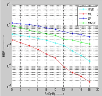
[image:5.612.89.299.233.431.2]The bit error rate of 16-QAM modulation is presented in figure 3 and four receive antenna. Thus, we compare the performance in terms of BER for D = 2 and C = 4 of the proposed detector HISD, the optimal ML detector and linear sensors ZF and MMSE.
Figure. 3: BER as a function of SNR for a 4 × 4 MIMO system with 16-QAM modulation, comparing
the performance of detectors HISD, ML, ZF and MMSE with D= 2 and C = 4
Note that HISD performance is clearly near to those of ML detectors. HISD performance is better than ZF and MMSE equalizers. We present in the next section a complexity comparison between the 4 equalizers studied.
According to [8] and [9] , we proof that by increasing the number of transmitting antenna and one receiving antenna, the bit error rate decreases. This confirms that the plurality of antennas reduces the likelihood of losing information.
Provide a statement that what is expected, as stated in the "Introduction" chapter can ultimately result in "Results and Discussion" chapter, so there is compatibility. Moreover, it can also be added the prospect of the development of research results and application prospects of further studies into the next (based on result and discussion).
7. HISD COMPLEXITY
This section determines the computational complexity of the proposed detection algorithm. We first calculate the number of multiplication and addition / subtraction in the required diversification step. Assume for simplicity that m = n. In a case of worst scenario, the complexity budget for diversification is shown in Table 1.
The computational complexity of HISD expense of two parameters C and D where D is the number of estimated directions and C represents
the number of selected candidate points of xstart.
The algorithm can be divided into two parts. The first is the calculation of the inverse channel nickname of Moore-Penrose matrix defined by par H+= (HTH)-1HT and the second is the use of the singular value decomposition for the D eigenvectors. Thus, the predominant complexity
preparatory steps are O (n3) per data block
shown in Table 2.
Table 1: Complexity of calculating the diversification step for HISD detector
Addition/Subtraction Multiplication
HISD 2n3
+ '&n2 - ('n 2n3 +3n2
Table 2: Complexity Calculation for HISD detector
Addition/Soustraction Multiplication
HISD 2Dn3
ISSN: 1992-8645 www.jatit.org E-ISSN: 1817-3195
215 The second part of the algorithm is to be executed for each received vector. The number of additions and multiplications of the second part in the worst case is expressed in Table 2.4. Note that the greedy search method is repeated using θ = 2 times. In the most painful case, the total number of points attainable visited by the HISD algorithm is DCn θ + 2DN.
The complexity of the ML method is exponential. The performance of the proposed detector HISD is near ML performance, while the order of complexity in the worst case is lower than ML (against polynomial exponential). The algorithm HISD being substantially parallel, the average cycle number is equal to two. The HISD is well suited for high-speed hardware architecture. For example, one can use the greedy search method in a parallel manner on C independent start. Furthermore, each direction of the eigenvector can be studied separately.
8. FPGA IMPLEMENTATION
An FPGA is an integrated circuit composed of a large number of programmable logic elements connected to each other through a routing matrix, it is also programmable.
The FPGA device enables the programmability
of the target platform, similar to
microprocessors. A circuit structure is controlled by a configuration stream that can be compared to a program stored in a memory [11]. This structure allows the FPGA to emulate any circuit, only on condition that it is not too big to not exhaust the logical resources and routing the
FPGA. However, this flexibility of
programmability is paid at the circuit
performance. Although FPGAs are engraved with the same technology that generalist
processors clocked at a few gigahertz, the FPGAs of clock frequency does not exceed a few
hundred megahertz for newer models.
Nevertheless, the great architectural freedom can make the most of fine-grained parallelism of the implemented circuits, which largely compensates for the low frequencies achievable. The language used is VHDL.
The VHDL language has been often used for implementing digital applications, hence its use in our work. The VHDL is a hardware description language for describing digital designs. The VHDL simplifies the development of complex systems such as Metaheuristic algorithm because it is possible to model and simulate a digital system from a high level of abstraction and with important facilities for modular design [12] , By using the VHDL, the circuit design shows some advantages: i) the
implementation technology independence
facilitates the migration to a newer technology, ii) it increases modular reusability, iii) it facilitates the automatic circuit generation, iv) it makes easy understanding of the high level code [13].
The finite state machines are used to describe sequential behavior related to the control of
operative parts. This makes sequential
appearance in the notion of internal state circuits implemented in the form of records.
ISSN: 1992-8645 www.jatit.org E-ISSN: 1817-3195
216
Fig.4: Flowchart of the proposed detection algorithm HISD
The control unit of the HISD algorithm generates suitable control signals to control the operation of different blocks of the logic process. This control unit is broken down into a hierarchy
ISSN: 1992-8645 www.jatit.org E-ISSN: 1817-3195
[image:8.612.90.532.65.429.2]217
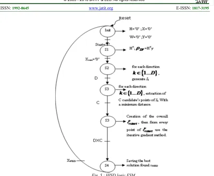
Fig. 5 : HISD logic FSM
In this paper, the FSM shown in figure 5 is defined by five states. At each clock front, one state is activated permitting the generation of the control signals and thus activating a new block of the design.
We present a design method of different detectors studied before when they are implemented in FPGA. We develop the result of HISD equalization algorithm implementation.
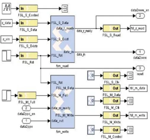
The software tools used are MATLAB, Xilinx ISE, and ModelSim.. The measurements have been simulated from the pose given in the database and corrupted with noises consistent with the ones encountered in the real test bench [15]. Figure 6 show the general model design of equalizer used in Simulink and XSG.
[image:8.612.189.463.546.706.2]ISSN: 1992-8645 www.jatit.org E-ISSN: 1817-3195
218 The yellow blocks represent the Gateway-in and the Gateway-out blocks. The other blocks are elementary blocks from the Xilinx block set which are essentially multipliers and adders and also some sub-systems doing complex addition and complex multiplication.
After designing the time domain model, we proceed to the FPGA implementation which is automatically done by the System Generator for DSP tool. It uses the Xilinx ISE 11.1 version to do all the flow.
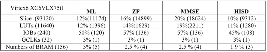
We implement hardware architecture of MIMO equalizers systems based on Modified HSID. Once the algorithm was uploaded from the compact flash to be processed by the FPGA processor, start interruption was activated [16]. The design Of HISD equalizer will be implemented in FPGA board with one million gates. The Table 3 gives and clear idea about the FPGA logic blocks consumption by the design. The Table 4 gives the results of equalizers implementation using Virtex6 (XC6VLX75tl) FPGA.
[image:9.612.192.445.257.494.2]Figure 13: A system Generator description of the design of equalizers
ISSN: 1992-8645 www.jatit.org E-ISSN: 1817-3195
[image:10.612.84.530.136.224.2]219
Table 4: Comparison Of Hardware Resources For Equalizers
Virtex6 XC6VLX75tl
ML ZF MMSE HISD
Slice (93120) 12%(11174) 16% (14899) 20% (18624) 10% (9312)
LUTs (11640) 12% (1396) 14%(1629) 19%(2211) 11% (1280)
IOBs (240) 50% (120) 57% (136) 57% (136) 45% (108)
GCLKs (32) 3% (1) 3% (1) 3% (1) 3% (1)
Numbers of BRAM (156) 3% (5) 2.5 % (4) 2.5 % (4) 1.9 % (3)
Table 4 shows that the HISD approach has the better material performances than the others detectors.
The implementation results have the following execution time for MIMO system using
modulation QAM 16 (n=5; m=6, C=4, D=2), Clock frequency is 50 MHz, and 80,000 data is sent continuously.
Table 6: ML And HISD Execution Time Results
Clock period (ns) 20 30 40 60
ML 120 210 260 275
HISD 110 180 240 260
The execution time increases, however,
increases the clock period, so it is preferably to work with the smallest clock period to save runtime. The FPGA implementation shows in table 6 that the HISD approach has the better execution time than ML detector.
Simulation with ModelSim gives a curve which represents the performance of the ML detector and rated BER as a function of SNR practically identical to that obtained with Matlab, with a notable advantage: insurance real time while reducing execution time since we have found that the execution time given by the simulation in ModelSim (worth 240 ns) is much lower than that given by Matlab (worth 13.198 s).
9. CONCLUSION
In this paper, we focused on developing a new sub optimal detection method capable of giving a good approximation to the optimal solution and reduce the complexity of the ML detection problem. We proposed a sub-optimal method for maximum likelihood detection problem. This method is based on two complementary research
techniques including: diversification and
intensification. The diversification phase is
defined by the search all feasible points near D
straight through the ρZF solution and direction D
singular vectors of the matrix H. The scale-up is a simple local search, the method named greedy search. The presented method is able to produce a performance near to ML performance with
constant computational complexity in
polynomial time.
Our work is oriented subsequently to the implementation of FPGA detectors where one was interested mainly in the most optimum ML compared to HISD method.
The results of implementation show a better execution time and small hardware resources. HISD is well suited for hardware implementation due to its near-optimal performance, reduced complexity and its highly parallel structure, future work will treat the implementation of this algorithm
ISSN: 1992-8645 www.jatit.org E-ISSN: 1817-3195
220
REFERENCES
[1] R.Dagoberto, Z. Roger , Improving the
Quality of Heuristic Solutions for the Capacitated Vertex p-Center Problem through Iterated Greedy Local Search and
Variable Neighborhood Descent,
Computers & Operations Research,
Volume 62, October 2015, Pages 133–144.
[2] P. H. Tan and L. K. Rasmussen, Tabu
search multiuser detection in CDMA, Radio
Sci. and Comm. Conf., Stockholm,
Sweden, pp. 744-748, Jun 2002.
[3] R. Chen, R. Koetter, D. Agrawal, and U.
Madhow, " Joint noncoherent demodulation and decoding for the block fading channel: a practical framework for approaching Shannon capacity”, IEEE Trans. Comm, Vol. 51, pp. 1676-1689, 2003.
[4] A.Aloisio, V. Izzo, and S. Rampone,
Member, IEEE, FPGA Implementation of a Greedy Algorithm for Set Covering, Real Time Conference, Stockholm. 14th IEEE-NPSS , 2005.
[5] H. Artes, D. Seethaler, and F. Hlawatsch.
Efficient detection algorithms for MIMO channels : A geometrical approach to approximate ML detection. IEEE Trans. Signal Processing, vol. 51, pp. 2808 2820, Nov. 2003.
[6] A. Nafkha, C. Roland, E. Boutillon. A
Near-optimal Multiuser Detector for
MC-CDMA Systems using Geometrical
Approach. ICASSP’05, Philadelphia ,
March 2005.
[7] A. Nafkha, C. Roland, E. Boutillon, HISD :
un nouveau décodeur MIMO utilisant une
approche géométrique pour des
transmissions MAQ, GRETSI - Actes de Colloques, 2005.
[8] C. He, Z.Tan, Q. Chen, C. Sha, Repair
diversification: A new approach for data repairing, Information Sciences Elsevier, 2016.
[9] A.Trimeche, A.Ben Abdallah, A.Sakly,
A.Mtibaa, detection algorithm for
Metaheuristic Maximum-Likelihood,
International Review of Automatic Control (I.RE.A.CO.), 2013.
[10] M. Lozano , F.J.Rodriguez, D.Peralta, C.G.Martínez, Randomized greedy multi-start algorithm for the minimum common integer partition problem, Engineering Applications of Artificial Intelligence, Pages 226–235, Elsevier , 2016.
[11] A.Milik, On Hardware Synthesis and Implementation of PLC Programs in
FPGAs, Microprocessors and
Microsystems, Elsevier, 2016.
[12] D.L. Perry. “VHDL programming by examples”, New York Mc Graw-Hill, 2004. [13] A. Nelson, T. Marcelo, “Custom
Architecture for Fuzzy and Neural
Networks Controllers”, Journal of
Computer Science and Technology, Vol.2, No.7, October 2002.
[14] S.Gdaim, A.Mtibaa, M.F.Mimouni, Design and Experimental Implementation of DTC of Induction Machine based on Fuzzy
Logic Control on FPGA, IEEE
Transactions on Fuzzy Systems, 2015. [15] J.L Beuchat, FPGA implementations of the
RC6 block cipher, Field-Programmable Logic and Applications: 13thInternational Conference, computer sciences, Springer, 2003.
[16] C.T.Huitzil , B. Girau, FPGA
implementation of an excitatory and inhibitory connectionist model for motion perception, , IEEE International Conference
on Field-Programmable Technology
(FPT’05), pages 259–266, Singapore,