http://dx.doi.org/10.4236/msa.2014.53019
How to cite this paper: Araújo, R. and da Silva Dias, A.M. (2014) Numerical Evaluation of Strength in the Interface during Indentation Spherical Testing in Thin Films. Materials Sciences and Applications, 5, 149-157.
http://dx.doi.org/10.4236/msa.2014.53019
Numerical Evaluation of Strength in the
Interface during Indentation Spherical
Testing in Thin Films
Rodrigo Araújo1, Avelino Manuel da Silva Dias2*
1Federal University of São João Del-Rei (UFSJ), São João Del-Rei, Brazil 2Federal University of Rio Grande do Norte (UFRN), Natal, Brazil
Email: [email protected], *[email protected]
Received 27 December 2013; revised 3 February 2014; accepted 21 February 2014
Copyright © 2014 by authors and Scientific Research Publishing Inc.
This work is licensed under the Creative Commons Attribution International License (CC BY).
http://creativecommons.org/licenses/by/4.0/
Abstract
The need for more components that are more resistant to wear and corrosion has promoted a growing interest in surface engineering. The search for improved tribological properties in mate- rials contributes to the development of processes that extend the useful life of components and their applications in increasingly severe environments. In this respect, thin ceramic coatings have been used to enhance the tribological properties of components that operate under these condi- tions. However, new experimental assays are needed to assess the behaviour of these films and their surface as substrate. These experimental analyses require the use of sophisticated equip- ment and specialized personnel. On the other hand, with advances in computational mechanics, the application of numerical analysis to solve numerous technological problems has been increa- singly frequent, owing to its low operational costs. This study aims to simulate an indentation as- say with spherical penetrator in systems composed of thin ceramic film deposited on metallic substrate using a Finite Element commercial code. The main objective of this study was to evaluate the field behaviour of stresses in the contact region of the indenter with the sample, on the outline of the impression made by the penetrator and, primarily, on the film-substrate interface.
Keywords
Finite Elements; Indentation Test; Thin Films
1. Introduction
face engineering. This field of engineering involves the preparation and modification of surfaces to fulfill spe- cific functions within certain applications. One of the options employed to improve these surface properties is the use of ceramic coatings obtained by deposition processes such as PVD. However, the mechanical properties of these films and their interface as substrate must be assessed. Instrumented indentation testing has been used to characterize these tribological systems [1].
Indentation tests have been applied to determine surface hardness in different classes of materials [2]. On the other hand, the instrumented indentation test is conducted using precision equipment equipped with sensors that monitor variations in penetration depth (h) of a penetrator as a function of applied load (F), when it penetrates the study material, reaching maximum displacement, then returning to the initial position, completing a loading and unloading cycle. However, implementation of this indentation technique to assess mechanical properties and the results obtained still raise doubts in the scientific community. According to the literature, these problems are more serious when assessing the mechanical behaviour of thin films deposited on soft substrates [3]. However, due to their versatility, a large number of studies have been carried out to investigate new technologies and ap- plications for these assays. Recent proposals used indentation tests as a tool to assess the mechanical characte- ristics of materials and surface hardness, such as modulus of elasticity (E), Poisson’s ratio (ν), fracture toughness (KIC) and a stress curve as a function of elastic/plastic strain behaviour [4]-[7].
Due to these limitations in analyzing indentation tests, the use of a numerical technique capable of evaluating stresses and strains during the indentation cycle may contribute to a better interpretation of this test. In recent decades, this numerical methodology has been studied using the finite/discrete element model to assess the be- haviour of different materials in the indentation test [8]-[10].
The Finite Element Method (FEM) has proved to be a reliable numerical technique for analyzing stresses and strains and simulating different engineering problems. This method has been widely used to simulate and re- solve numerous nonlinear problems related to structural instability, and dynamic, electromagnetic and mechani- cal conformation systems. However, the use of this numerical technique to assess the indentation test in thin surface coatings, has also posed problems due to computational limitations, difficulty in implementing damage criteria and mainly, in characterizing these coatings [7] [10].
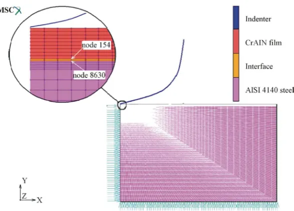
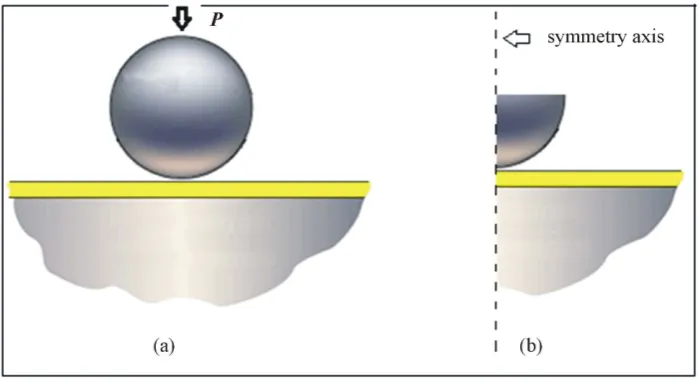
[image:2.595.140.490.504.695.2]The simulation proposed in this study will use discrete/finite element models to reproduce the indentation test with a spherical indenter, as illustrated in Figure 1. The system under study was composed of a metallic sub- strate coated with different thicknesses of ceramic film. In the numerical procedure, the influence of friction between the penetrator and surface of the film, effects of coating thickness, elasticity properties, mechanical strength and development of stress and strain fields were assessed. Simulation was used to assess the mechanical behaviour of the interface in these systems that combine high-hardness coatings with a middle-hardness sub- strate. This interface was modeled by introducing a thin layer of elements with mechanical properties capable of simulations ranging from perfect adhesion to possible delamination of the film.
2. Methodology
The numerical simulation performed in this study used the finite element method and MARC™ software to model the indentation test with a spherical penetrator in a thin ceramic film deposited on a metallic substrate [11]. Due to the symmetry of the problem, asymmetric elements were used in the numerical model, significantly decreasing computational efforts [1]. The system studied was composed of an AISI 4140 low-alloy steel sub- strate coated with a chromium aluminum nitride (CrAlN) film, with the following thicknesses: 1.67 μm, 3.00 μm, 6.00 μm and 9.00 μm. The materials studied, of both the film and the substrate, were considered isotropic and homogeneous. The elastic-plastic behaviour of these materials under compression was illustrated by means of a curve depicting the linear elastic regime and plastic yield (Equation (1)), as described by Hosford and Caddell [12]. In this expression, σ, ε, E are effective stress, effective strain and Young’s Modulus, respectively. K and n
are constants that describe the strain hardening characteristics of the material, n known as the strain hardening coefficient [13].
(
)
(
)
1 0.
n
E elastic phase
K plastic phase
ε σ
ε
=
[image:3.595.165.465.666.722.2] (1)
Table 1 shows the mechanical properties of the film and substrate adopted in the present study. The experi- mental values of yield strength (σo) and Poisson’s ratio (ν), as well as Equation (1) data, were obtained from the literature [6] [14].
The indentation cycle (loading and unloading) was simulated using the prescribed displacement of the pene- trator, allowing better numerical control at the outset and during simulation of the test [10]. In addition to this numerical control, the test was executed in two phases, one on the downstroke of the penetrator, and the other on the upstroke, completing the cycle. Incremental analysis of the problem used one hundred centimeters for both the loading and unloading phases.
Numerical representation used four-node isoparametric flat elements. In order to obtain better distribution of field stresses and strains in the contact region of the indenter and at the interface with the substrate, a more re- fined grid was used in these regions (Figure 2). The decrease in element size increases their number in these re- gions, raising computational costs, but reducing instability in the numerical result of the loading curve as a func-tion of displacement in these simulafunc-tions [1].
In an attempt at simulating interface behaviour during the tests, a layer was introduced between the film and substrate, with the lowest thickness possible (Figure 2). This layer was modeled with a thickness of 0.17 μm and perfectly plastic elastic-mechanical behaviour, in order to allow slip between the film and substrate. The yield strength (σo) adopted for this layer is the same as the substrate, that is, 565 MPa. To assess its behaviour,
its modulus of elasticity (E) was varied between 238 GPa and 1.0 GPa. The former value is equal to the modulus of elasticity of the substrate, representing perfect adhesion. The latter value represented weak adhesion of the film to the substrate. The characteristics of the grids used in the different numerical models are listed in Table 2.
Indenter penetration depths of 10%, 20% and 50% of film thickness were adopted. According to the literature, a penetration depth of up to 10% of film thickness is used when studying film without the influence of the sub- strate [15] [16]. Other authors recommend that this thickness be up to 20% when the substrate exhibits high me- chanical strength [6]. To assess behaviour between the film and the substrate system, the present study adopted a depth of half the film thickness. Finally, a friction coefficient with values ranging from 0.1 to 1.0 was introduced between the indenter and the film [1] [16] [17].
3. Results & Discussions
All situations simulated demonstrated that friction between the penetrator and the surface of the film has no sig- nificant influence on indentation load. This analysis also showed that thicker films cause an average increase of
Table 1. Mechanical properties adopted for the film and substrate [6] [14].
Material E (GPa) ν σo (MPa) K (MPa) n
Substrate (AISI 4140 steel) 238 0.29 565 2230 0.228
Figure 2. Numerical mesh of spherical indentation testing in a system with film, interface and substrate.
Table 2. Characteristics of the grid of numerical models simulated with a system composed of a film, interface and substrate.
System Substrate Interface Film Film thickness
CrAlN film—AISI
4140 steel substrate 7920 elements 105 elements
525 elements 1.67 μm
945 elements 3.00 μm
1890 elements 6.00 μm
2835 elements 9.00 μm
2.7% in indentation load, considering the same penetration depth in conjugate with twice the film thickness. Figure 3 illustrates the behaviour of the load curve as a function of indenter displacement in the simulation of a test conducted in a sample of 1.67 μm-thick film, considering an indentation depth of 10%, that is, 0.17 μm. In this simulation, the interface layer was modeled with a modulus of elasticity of 2.0 GPa. The curve generated shows that the numerical assay is a qualitative representation of experimental behaviour compared to other lite- rature studies [3]-[7].
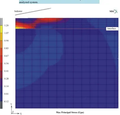
For this simulated case, Figure 4 depicts the numerical distribution of Maximum Principal Stress after un- loading. This distribution of stresses in contact and interface regions shows the same behaviour as in earlier stu- dies [1] [18]. Possible delamination, evidenced by the stress field formed in the interface region, was also ob- served. This confirms other results found in the literature, which demonstrates that thinner films exhibit greater tendency of delamination damage during indentation testing with spherical indenters [5] [8] [18].
Table 3 shows the numerical results obtained for the indentation load as a function of the variation in the modulus of elasticity of the surface layer, for a system with a 3.00 µm-thick film. The first line of this table shows the result, considering perfect adhesion between the film and the substrate, where the module of elasticity of the interface is equal to that of the substrate. Gradually decreasing the value of this modulus of elasticity si- mulates an indentation test in a system with low adhesion between the film and substrate. These numerical re- sults exhibit little variation in maximum indentation load as a function of variation in the modulus of elasticity of the interface. However, for low modulus of elasticity values, that is, below 4.0 GPa, a significant decline in indentation load takes place. Table 3 also demonstrates that this behaviour repeats itself for different penetration depths. The lower indentation load value indicated that the system does not exhibit good tribological properties, suggesting possible damage or film delamination.
Figure 3. Load curve as a function of indenter displacement in the analyzed system.
[image:5.595.122.509.327.696.2]Table 3. Maximum indentation load as a function of the modulus of elasticity of the interface, for a system with 3.00-thick film and different penetration depths.
Interface Young’s Modulus (GPa)
Indentation load (N)
hmax = 10% of film thickness hmax = 20% of film thickness hmax = half film thickness
238 20.15 36.10 70.88
200 20.10 36.01 70.73
100 20.04 35.95 70.68
50 19.94 35.84 70.60
20 19.67 35.52 70.35
10 19.25 35.04 69.97
9.0 19.17 34.95 69.90
8.0 19.06 34.84 69.80
7.0 18.94 34.72 69.68
6.0 18.78 34.54 69.53
5.0 18.57 34.32 69.34
4.0 18.27 34.04 69.06
3.0 17.82 33.54 68.66
2.0 17.06 32.71 68.02
1.0 15.42 31.14 66.85
Figure 5. Graph of Maximum Principal Stress on the interface as a function of variation in the modulus of elasticity of this layer, for a system with 3.00 μm-thick film.
numerical results of Maximum Principal Stress behaviour as a function of variation in the modulus of elasticity of the interface are illustrated in Figure 5. The indentation test behaviour was recorded in a system with 3.00 μm-thick film for penetration depths of 20% and 50% of film thickness, since, according to the literature, inden- tation tests with penetration depths of less than 10% of film thickness show no influence from the substrate, that is, from interface behaviour [3] [6].
[image:6.595.135.490.116.601.2]at the interface. This behaviour also seems to confirm that the numerical representation of film delamination during the indentation test for low modulus of elasticity values at the interface. In these simulated cases with low modulus of elasticity at the interface, the stress field produced by the indenter is redistributed within the film, with minor or no influence from the mechanical strength of the substrate.
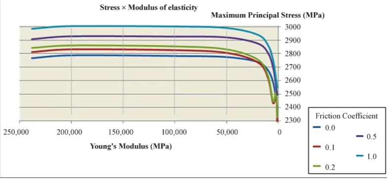
Figure 6 shows the numerical result obtained for Maximum Principal Stress at the interface as a function of the decrease in the modulus of elasticity of the surface layer. In this analysis, different friction coefficient values were considered between the indenter and the sample, in a system with 3.00 µm-thick film and penetration depth of 20% of this thickness. These results show that the variation in the friction coefficient between the penetrator and the film surface has an influence on the distribution of the stress field in the film [1] [16] [18]. The same stress field behaviour was observed at the interface as a function of the decrease in modulus of elasticity, that is, the Maximum Principal Stress at the interface declines to low modulus of elasticity values at the interface. Once again we have the numerical representation of the indentation test with film delamination.
For major indenter penetration depths using in the present work (Figure 7), stress field variability as a func- tion of friction coefficient is lower when compared to the test with a minor indentation. However, for low mod- ulus of elasticity values at the interface, Maximum Principal Stress continues to decline in this region.
[image:7.595.116.513.507.685.2]Figure 6. Graph of Maximum Principal Stress on the interface as a function of variation in the modulus of elasticity of this layer, for a system with 3.00 μm-thick film, with an indentation depth of 20% of this thick- ness and with different friction coefficient values.
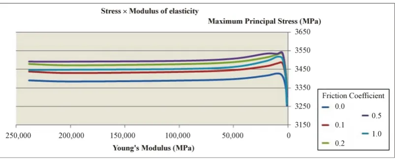
Figure 8. Graph of Maximum Principal Stress on the interface as a function of variation in the modulus of elas- ticity of this layer, for a system with 9.00 μm-thick film, with an indentation depth of half thickness and chang- ing the friction coefficient.
Finally, Figure 8 illustrates Maximum Principal Stress behaviour as a function of the variation in the modulus of elasticity at the interface for a system with 9 µm-thick film and penetration depth equal to half of film thick- ness. The friction coefficient was also varied. There was a decrease in stress field too at the interface with a re- duction in the modulus of elasticity at the interface. However, the influence of friction was not linear, since in simulations with lower thickness, the intensity of the stress field increased with a rise in the friction coefficient. This Figure also shows that the highest stress field level occurs when a friction coefficient of 0.5 is used. It can therefore be concluded that the greater the film thickness, the smaller its influence on stress field behaviour at the film-substrate interface.
4. Conclusions
Based on the numerical results of the indentation test with spherical indenters using the finite element method, it was concluded that from the global behaviour viewpoint, the models represented the indentation test in different systems composed of a hard film (CrAlN), with different thicknesses, deposited in a metallic substrate with high mechanical strength (AISI 4140 steel). In all the simulated simulations of the present study, it was confirmed that friction between the indenter and the surface of the film has a greater influence on the stress field than on indentation load.
The stress field in the film was assessed for different models with the incorporation of a layer capable of representing the interface with behaviour ranging from perfect to weak adhesion. These results showed the pos- sibility of adhesive damage in models with the use of low modulus of elasticity values at the interface. However, there is still a need for more thorough numerical and experimental analysis in order to introduce a parameter ca- pable of more representative modeling of film-substrate adhesion.
Acknowledgements
This research work had financial support by CNPq (Federal Brazilian Foundation for the support of the re- search).
References
[1] Araújo, R., Dias, A.M.S. and Godoy, G.C.D. (2013) Estudo Numérico da Influência do Coeficiente de Atrito no Ensaio de Dureza em Filmes Finos. Revista Matéria, 18, 55-66. (in Portuguese)
http://dx.doi.org/10.1590/S1517-70762013000100008
[2] Souza, S.A. (2000) Ensaios Mecânicos de Materiais Metálicos: Fundamentos teóricos e práticos. 5th Edition, Edgard Blücher LTD, São Paulo. (in Portuguese)
[4] Zeng, K. and Chiu, C-H. (2001) An Analysis of Load-Penetration Curves from Instrumented Indentation. Acta Mate- rialia, 49, 3539-3551. http://dx.doi.org/10.1016/j.surfcoat.2005.03.018
[5] Lee, H., Lee, J.H. and Pharr, G.M. (2005) A Numerical Approach to Spherical Indentation Techniques for Material Property Evaluation. Journal of the Mechanics and Physics of Solids, 53, 2073-2069.
http://dx.doi.org/10.1016/j.jmps.2005.04.007
[6] Dias, A.M.S. and Godoy, G.C.D. (2010) Determination of Stress-Strain Curve through Berkovich Indentation Testing.
Materials Science Forum, 636-637, 1186-1193. http://dx.doi.org/10.4028/www.scientific.net/MSF.636-637.1186
[7] Mousse, C., Mauvoisin, G., Bartier, O., Pilvin, P. and Delattre, G. (2012) Characterization of Homogenous and Plasti- cally Graded Materials with Spherical Indentation and Inverse Analysis. Journal of Materials Research, 27, 20-27.
http://dx.doi.org/10.1557/jmr.2011.303
[8] Sun, Y., Bloyce, A. and Bell, T. (1995) Finite Element Analysis of Plastic Deformation of Various TiN Coating/Sub- strate Systems under Normal Contact with a Rigid Sphere. Thin Solid Films, 271, 122-131.
http://dx.doi.org/10.1557/jmr.2011.303
[9] Souza, R.M., Mustoe, G.G.W. and Moore, J.J. (2001) Finite Element Modeling of the Stresses, Fracture and Delamina- tion during the Indentation of Hard Elastic Films on Elastic-Plastic Soft Substrates. Thin Solid Films, 392, 65-74.
http://dx.doi.org/10.1016/S0040-6090(01)00959-2
[10] Dias, A.M.S., Modenesi, P.J. and Godoy, G.C. (2006) Computer Simulation of Stress Distribution during Vickers Hardness Testing of WC-6Co. Materials Research, 9, 73-76. http://dx.doi.org/10.1590/S1516-14392006000100014
[11] Msc.MARC (2012) Volume A: Theory and User Information. Users Manual. MSC.Software Solutions Download Center. http://www.mscsoftware.com/
[12] Hosford, W.F. and Caddell, R.M. (1993) Metal Forming. Prentice Hall, Inc., Upper Saddle River.
[13] Begley, M.R., Evans, A.G. and Hutchinson, J.W. (1999) Spherical Impression of Thin Films on Elastic-Plastic Sub- strates. International Journal of Solids and structures, 36, 2773-2788.
http://dx.doi.org/10.1590/S1516-14392006000100014
[14] Matweb (2013).
http://www.matweb.com/search/MaterialGroupSearch.aspx
[15] Lichinchi, M., Lenardi, C., Haupt, J. and Vitali, R. (1998) Simulation of Berkovich Nanoindentation Experiments on Thin Films Using Finite Element Method. Thin Solid Films, 333, 278-286.
[16] Huang, X. and Pelegri, A.A. (2005) Mechanical Characterization of Thin Film Materials with Nanoindentation Mea-surements and FE Analysis. Journal of Composite Materials, 40, 1393-1407.
http://dx.doi.org/10.1177/0021998305059728
[17] Dias, A.M.S., Sotani, P.F.B. and Godoy, G.C. (2010) Simulação do Ensaio de Indentação em Filmes Finos com o Uso de Modelos de Trinca Difusa. Revista Matéria, 15, 422-430. (in Portuguese)
http://dx.doi.org/10.1590/S1517-70762010000300005
![Table 1. Mechanical properties adopted for the film and substrate [6] [14].](https://thumb-us.123doks.com/thumbv2/123dok_us/8009881.763933/3.595.165.465.666.722/table-mechanical-properties-adopted-film-substrate.webp)