by
Ali A. Abbas, Sharifah M. Syed Mohsin, Demetrios M. Cotsovos
and Ana M. Ruiz-Teran
Reprinted from
1. INTRODUCTION
Numerous experimental and analytical investigations (e.g. Swamy and Al-Ta’an 1981; Mansur et al. 1986; Bayasi and Gebman 2002; Cho and Kim 2003; Tlemat
et al. 2006; Campione and Mangiavillano 2008) have been carried out to study how the addition of steel fibres can improve the performance of conventionally reinforced-concrete structures. The studies have shown that steel fibres enhance the ductility of what is
Loads
Ali A. Abbas
1,*, Sharifah M. Syed Mohsin
2, Demetrios M. Cotsovos
3and Ana M. Ruiz-Teran
41School of Architecture, Computing and Engineering, University of East London, London, UK 2Faculty of Civil & Earth Resources, University Malaysia Pahang, Lebuhraya Tun Razak 26300, Malaysia 3Institute of Infrastructure and Environment, School of the Built Environment, Heriot-Watt University, Edinburgh, UK
4Department of Civil and Environmental Engineering, Imperial College London, London, UK
(Received: 16 July 2013; Received revised form 3 April 2014; Accepted: 23 May 2014)
Abstract: The present study is aimed at examining the structural response of steel-fibre-reinforced concrete (SFRC) columns under reversed-cyclic loading, which were investigated by means of non-linear finite-element analysis (NLFEA). The focus was on investigating the potential of steel fibres in compensating for reduction in conventional transverse reinforcement [and thus the spacing between shear links was increased by 50% and 100% while the fibre volume fraction (Vf) was increased to 1%,
1.5%, 2% and 2.5%]. This is useful in situations where the latter is required in significant amounts (e.g. in seismic design) leading to congestion and practical difficulties in placing the links. The critical factor in the seismic response is the cyclic nature of the load, which is examined in the present research work. An interesting feature of the present research work is the consideration of statically-indeterminate SFRC columns, information on which is rare as previous research studies have focused on simply-supported beams. To address this, both indeterminacy and axial loads were considered in the present investigation. Calibration work was carried out using existing experimental data and good correlation was established between numerical and test results. Subsequently, parametric studies were carried out using the practical range of fibre dosages, which provided insight into how the steel fibres can help reduce the amount of conventional shear links.
Key words:fibre-reinforced concrete; finite element methods; structural analysis; cyclic loading; seismic design; ductility.
otherwise a brittle plain-concrete material. It is important to reduce the brittleness of plain concrete and introduce a crack control mechanism thus changing the failure mode to one that includes post-cracking ductility (Hannant 1978). This is useful to avoid sudden modes of collapse such as shear failure. Many researchers such as Swamy and Bahia (1985); Sharma (1986); Narayanan and Darwish (1987); El-Niema (1991); Kwak et al.
(2002); Campione et al. (2006) studied the effect of
considered). In this manner, the potential for steel fibres to substitute for a reduction in conventional transverse reinforcement was examined. This is particularly useful in situations where the conventional transverse reinforcement required can lead to congestion of shear links, for instance in seismic design (Eurocode 8 2004). Conclusions were thus made on the potential for fibres to compensate for reduction in conventional transverse reinforcement. The studies also helped improve understanding of how steel fibres can help enhance the energy dissipation, which is crucial in seismic design. Axial loads have also been considered so that gravity loads on columns can be included (again, previous work on SFRC in the literature was predominantly focused on lateral loads on beams). This allows the study of SFRC columns under both gravity and lateral seismic loads, with the reversed-cyclic nature of the latter modelled in the present study. The present paper is part of a research project, which has also examined SFRC columns under monotonic loads in its first phase with the findings reported elsewhere (Syed Mohsin 2012; Abbas et al.
2014a).
2. METHOD ADOPTED
The structural response of SFRC elements is characterised by its tensile post-cracking behaviour. The effect of the steel fibres is directly modelled into the existing concrete material model employed by ABAQUS (2007) to describe its nonlinear behaviour. This is achieved by appropriately modifying the stress-strain relationship of plain concrete in uniaxial tension to enhance its strain-softening and -hardening characteristics. A summary of the method adopted in the present study is summarised next.
2.1. SFRC Constitutive Models
A number of available constitutive models for SFRC have been identified such as those proposed by RILEM (2000, 2003); Barros (1999, 2001); Tlemat et al.(2006); Lok and Pei (1998); Lok and Xiao (1999). The constitutive relations have been developed to describe the uniaxial tensile stress-strain relationship of SFRC (in particular the post-cracking response allowing for more ductile characteristics compared to the brittle response of plain concrete). In these models, the residual strength beyond the cracking point of concrete is made up of two components, the steel fibres bridging the crack and the bond developing between the fibre and the surrounding concrete (leading eventually to pull-out failure when such bond is lost under increased loading). The main characteristics of the models have been closely studied and subsequent calibration work was undertaken by Syed Mohsin (2012); Abbas et al.
fibre content on enhancement of shear capacity and confinement, particularly in the absence of conventional shear reinforcement in some investigations. Furthermore, improvements to ductility and energy absorption are particularly beneficial for structures under seismic loading. Nevertheless, there is a clear gap in the literature on the application of steel-fibre-reinforced concrete (SFRC) constitutive models to study the potential of utilising fibres to enhance the seismic – and thus cyclic – response of a structure and to assess the potential ductility and energy absorption capacity of such composites. Most of SFRC specimens studied in the literature are focused on simply-supported beams and information on statically-indeterminate columns is limited. To this end, the work presented in this article aims to examine the structural response of statically-indeterminate SFRC columns under reversed-cyclic loads using Non-linear Finite-Element Analysis (NLFEA). The column case studies considered have already been examined experimentally by Kotsovos et al.
(2007) and thus the accuracy of the NLFEA predictions can be readily ascertained. The experiments examined only a limited range of parameters (e.g. only two fibre dosages were considered). The NLFEA, on the other hand, have allowed for this to be extended to cover the full range of fibre volume fractions (Vf) and therefore yield more generic conclusions than those obtained from experimental investigations alone.
Initially, a critical review of available test data was carried out in order to assess the effect of the use of steel fibres on the material properties of structural concrete (Syed Mohsin 2012; Abbas et al. 2010a,b). As part of this review, a comprehensive survey was also carried out to collate and investigate the reliability of different constitutive models proposed for the numerical modelling of SFRC. Based on the findings of these studies and associated numerical calibration work, a suitable constitutive model was selected for the current study on columns. The model was implemented into a well-known commercial NLFEA package (ABAQUS 2007). Further calibration work was carried out using available sets of experimental data on columns tested by Kotsovos et al. (2007) and good correlation was established between NLFEA-based results and experimental data.
(2010a, b; 2012) to investigate these models. It was concluded that the model proposed by Lok and Xiao (1999) is more suitable to be adopted for the subsequent parametric studies on SFRC under cyclic conditions [a full description of the model and its parameters can be found elsewhere (Lok and Xiao 1999)]. Unlike many other SFRC models, Lok and Xiao (1999) model is applicable for a reasonably wide practical range of fibre volume fractions (i.e. 0.5% to 3.0%), which covers the range investigated in the present research work. The model is also versatile as it allows for different values of the fibre aspect ratio (L/d) and bond stress between concrete and steel fibres (τd) as well as taking into account the effect of the randomness in the distribution of fibres.
2.2. ABAQUS Model for SFRC
The material model adopted in ABAQUS (2007) to describe concrete behaviour is the “brittle cracking model”, which is available in ABAQUS/Explicit. This model is designed for cases in which the material behaviour is dominated by tensile cracking, which is the case for SFRC. In this respect, the post-cracking tensile stress-strain diagram is described using “tension stiffening”, which is usually adopted in NLFEA of concrete elements to allow for the enhancement provided by concrete between cracks or interaction between concrete and reinforcement. Therefore, this was conveniently used to input the post-cracking characteristics of the adopted Lok and Xiao (1999) SFRC model, such as residual and ultimate tensile stress and strain values into ABAQUS. Since the focus is on the all-important brittle tensile aspect of concrete behaviour, a simplification employed in the model is that the behaviour in compression is assumed to be linear elastic. This is justified, particularly for 3D modelling of concrete, as at least one of the three values of principal stresses needs to be tensile and exceeding the tensile strength to initiate cracking and ultimately failure (while the other two principal stresses could be compressive). The main attractive feature of the model is that it focuses on the main mechanisms for failure in concrete, namely its brittleness and cracking (predominantly in tension). Thus the simplification made with regards to compressive behaviour is intended to make the solution process more efficient without compromising its ability to mimic the nonlinear response of concrete structural elements and this was confirmed in the calibration work against experimental data. As a further precaution, the strain results were checked to ensure that the values of ultimate compressive strains did not exceed 0.0035 [the maximum allowed in Eurocode 2 (2004)] before failure.
A smeared crack approach is adopted to model the cracking process that concrete undergoes. For purposes of crack detection, a simple Rankine criterion is used to detect crack initiation (i.e. a crack forms when the maximum principal tensile stress exceeds the specified tensile strength of concrete). The crack surface is taken to be normal to the direction of the maximum tensile principal stress. Subsequent cracks may form with their surface orthogonal to the directions of any existing crack surface at the same point. Crack closing and reopening is allowed for (i.e. cracks can close completely when the stress across them becomes compressive). The crack opening and closing capability is important for accurate modelling of concrete under cyclic loading conditions. The amount of crack opening also affects the shear response. The shear stiffness of concrete decreases as the crack propagates and thus the shear modulus can be reduced accordingly. However, the shear stiffness does not diminish completely as there are mechanisms such as aggregate interlock and dowel action that ensure some stiffness is retained. Therefore, in the NLFEA of reinforced-concrete structures, the effect of aggregate interlock and dowel action is allowed for by means of “shear retention”. Fibres provide a similar enhancement to the shear resistance (i.e. in a direction parallel to the crack surface) and, therefore, it was modelled using the “shear retention” part of ABAQUS concrete model in the present study. To allow for degradation in shear stiffness due to crack propagation, the shear modulus was reduced in a linear fashion from full shear retention (i.e. no degradation) at the cracking strain to 50% of that value at the ultimate tensile strain. It must be pointed out that the fibres main contribution to shear resistance is due to its crack bridging role (i.e. in a direction perpendicular to the crack surface), which is similar to the manner in which shear links contribute to tension resistance across the crack. This is because the shear cracks are actually due to diagonal tension rather than direct shear, which affects deeper sections.
2007). To ensure that no significant dynamic effects occur as a result, the ratio between kinetic energy and strain energy was checked at each load step to ensure that it does not exceed 5%.
2.3. Case Studies Considered
The basic idealisation of the two-span continuous columns investigated numerically in the present study is schematically depicted in Figure 1(a). The statically-indeterminate arrangement allows for a study of the effect of fibres on strength, ductility as well as moment redistribution and formation of plastic hinges. The SFRC columns were initially examined experimentally by Kotsovos et al. (2007) and the salient features of the column specimens studied are summarised in Figure 1(b). The SFRC specimens (referred to in the experimental work as D16-FC30-C) were tested with steel fibres added at Vf= 0.4%. They were loaded with an axial force (N) first, which is equal to about 20% of the maximum value that can be sustained in pure compression (Nu). In addition, a lateral reversed-cyclic load (P) was also applied to represent the case of a column under both gravity and lateral seismic action. The cyclic load was applied using a displacement-based method at point C in Figure 1(b). Consequently, the load and deflection values taken to plot the ensuing load-deflection curves were also taken at point C. The concrete compressive strength for the specimen was approximately 37 MPa. In addition, the
longitudinal reinforcement has a yield stress (fy) of 555 MPa, whilst, the transverse reinforcement has a yield stress of 470 MPa. The modulus of elasticity for steel (Es) is 200 GPa. The steel fibres used are DRAMIX RC80/60BN, which are hooked-end fibres with length of 60 mm and diameter of 0.75 mm (i.e. with an aspect ratio
L/d=80). Steel plates of 20-mm thick and 100-mm wide were added to the column at the loading and support locations (this is to mimic experimental setup and also avoid premature localised failure).
2.4. Results of Calibration Work
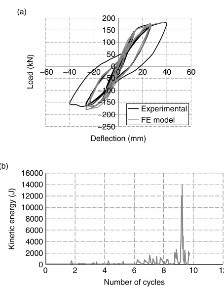
A comparison between experimental data and FE predictions for the SFRC columns subject to reversed-cyclic loading is presented in Figure 2(a). A summary of key values from the load-deflection hysteresis loop is presented in Table 1, with Py representing the load at yield, Pmaxthe maximum load achieved, Puthe ultimate load at failure, δythe deflection at yield, δuthe ultimate
deflection and µ the ductility (defined as ).
The table confirms the good agreement between the experimental and numerical data thus ensuring the validity of the FE model to simulate the behaviour of this structure under reversed-cyclic loading. The column
µ =δ δ
u
y
N = Constant axial load Inflexion point
N N
P = reversed-cyclic load (a)
(b)
975 mm
200 mm
200 mm
975 mm
1950 mm
1200 mm
2 T16 R8 2 T16 N
N
R8/40 R8/14 R8/40 R8/14 R8/40 R8/14 R8/40
300 mm 720 mm 560 mm 415 mm 560 mm 495 mm300 mm C
P
[image:5.595.316.543.413.707.2]P
Figure 1. (a) Schematic representation of SFRC continuous column under gravity and lateral loads (b) Loading arrangement and reinforcement detailing of the column (adapted from Kotsovos
et al.2007)
(a)
(b)
−60 −40 −20 00 50
Load (kN)
Deflection (mm)
Number of cycles −50
100
−100 150
−150 200
−200 −250
0
0 2 4 6 8 10 12
2000 4000 6000 8000 10000
Kinetic energy (J)
12000 14000 16000
20 40 60
Experimental FE model
Figure 2.(a) Calibration results comparison for the column analysed under reversed-cyclic loading (b) Kinetic energy figure to
[image:5.595.45.288.460.686.2]failed after 9.25 cycles in the NLFEA, which was determined based on the significant sudden jump in the kinetic energy as evident in Figure 2(b) indicating the presence of large/extensive cracks that were judged to impair structural integrity. The cracking pattern obtained at failure is presented in Figure 3. The higher stress concentrations are observed at the point where the load P is applied, at the mid-span of the first column span and at the intermediate support. Cracks developed in these regions, where steel fibres bridging and restraining these cracks are now being pulled out. From the cracking pattern and deflected shape of the column depicted in Figure 3, it can be concluded that the column failed in bending at the section where the load P is applied. This agrees with the experimental observation.
[image:6.595.42.554.79.146.2]The calibration work was also an important initial step in the present study as it allowed the determination of some parameters needed for the numerical simulations. For instance, the calibration involved sensitivity analyses using different mesh sizes, which resulted in brick elements with width 30 mm being selected for the subsequent parametric studies as this mesh produced the best agreement with the experimental data (i.e. the mesh which best replicates the true structural responses). Thus, the calibration work was crucial in order to ascertain the accuracy of the numerical predictions. The generality of the NLFEA model adopted was validated on different SFRC structural configuration such as simply-supported beams (Abbas et al.2014b), beam-column joints (Abbas Table 1. Summary of calibration work under reversed-cyclic loading
Py δy Pu δu Pmax δpmax
Column (kN) (mm) (kN) (mm) (kN) (mm)
Experimental 97.1 8.0 177.2 40.1 183.0 37.7 5.0 1.89
FE model 94.6 8.0 181.5 37.7 181.5 37.7 4.7 1.92
P Py
max
µµ δδ δδ = u
y
(a)
(d) (b)
(c) S, S11 (Avg: 75%)
+2.922e + 01 +3.700e + 00 +3.083e − 01 −3.083e + 00 −6.475e + 00 −9.867e + 00 −1.326e + 01 −1.665e + 01 −2.004e + 01 −2.343e + 01 −2.683e + 01 −3.022e + 01 −3.361e + 01 −3.700e + 01 −9.707e + 01
LE, LE11 (Avg: 75%)
+8.634e − 02 +2.000e − 02 +1.804e − 02 +1.608e − 02 +1.412e − 02 +1.217e − 02 +1.021e − 02 +8.250e − 03 +6.292e − 03 +4.333e − 03 +2.375e − 03 +4.167e − 04 −1.542e − 03 −3.500e − 03
P
N2 N1
R1H
R2
R3 R1V
[image:6.595.65.527.402.716.2]et al. 2014c), in addition to the present continuous column case. Furthermore, calibrations on RC beams (i.e. without fibres) were carried out using experimental data on beams undergoing both ductile and brittle responses (i.e. Hughes and Spiers 1982; Bresler and Scordelis 1963, respectively). These analyses were carried out to ensure that the NLFEA software and associated constitutive model adopted yield good predictions for RC members, so that the effect of adding fibres can be quantified correctly when SFRC elements are modelled. Full details on these studies are provided elsewhere (Syed Mohsin 2012).
3. PARAMETRIC STUDIES ON
STATICALLY-INDETERMINATE SFRC COLUMNS
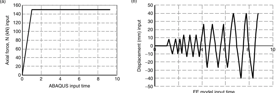
Following the calibration work, NLFEA-based parametric studies were carried out on statically-indeterminate SFRC columns under combined axial and reversed-cyclic lateral loads. The constant axial load N
was introduced directly as a force first and subsequently the lateral reversed-cyclic load P was applied using a displacement-based method to ensure numerical stability. The loading history adopted in the FE analyses for both forces is defined in Figure 4. The studies incorporate two key parameters, namely: the increase in spacing between stirrups (SI) and steel fibres volume fraction (Vf). In the experimental work, the SFRC specimens were tested with Vf=0.4%. In the numerical study currently presented, the spacing between the links was increased by 50% and 100% while Vfwas increased to 1%, 1.5%, 2% and 2.5%. This allowed for investigating the effect of fibre content and its potential in compensating for reduction in conventional transverse reinforcement. The tensile stress-strain relations for each fibre volume fraction are summarised in Figure 5. The results of the NLFEA-based parametric
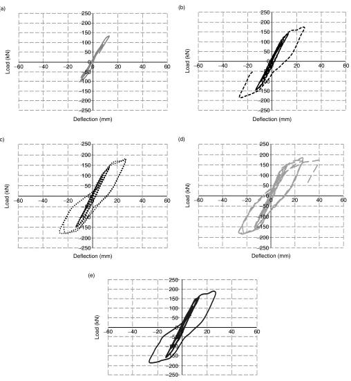
studies obtained are depicted in Figures 6(a) to (c) for columns with SI=0%, 50% and 100%, respectively.
Under reversed-cyclic loading, a consistent increase in the strength (i.e. Pmax) was observed, as the fibre
amount is increase. This is due to the fibres bridging the cracks and as a result a higher load is required in order to produce the same deflection level. Thus, the amount of fibres contributes to the increase in the strength and stiffness of the SFRC columns. In order to examine the results in more detail, Figures 7 to 9 were produced to show the results for each fibre volume fraction and the corresponding findings are discussed next.
3.1. Shear Link Spacing Increase SI =0%
The load-deflection hysteresis loops for specimens with increased stirrup spacing of SI = 0% are presented in Figures 7(a) to (e), respectively. Additionally, a summary of the key load and deflection results is provided in Table 2 (note Nc represents the number of cycles achieved before failure). The load-deflection curves show that there is a gradual increase in strength,
(a) (b)
ABAQUS input time
FE model input time 160
140
120
Axial force, N (kN) input
100
80
60
40
20
0
50
30 40
20
Displacement (mm) input
10
0 −10 −20 −30 −40 −50
0 2 4 6 8 10
[image:7.595.309.551.63.207.2]0 2 4 6 8 10
Figure 4.Loading history for: (a) constant axial force; and (b) reversed-cyclic loading
0 0 1 2 3 4 5 6
0.005 0.01 Strain (−)
Stress (MPa)
0.015 0.02 0.025
[image:7.595.64.536.566.725.2]Vf= 0% Vf= 1% Vf= 1.5% Vf= 2% Vf= 2.5%
stiffness and ductility as the fibres content is increased. However, in term of ductility, there is an improvement up to Vf=1%, but any additional fibres led to reduced – rather than increased – ductility. For columns with
Vf > 2%, the ductility has actually decreased even more than the ductility of column with no fibres. This suggests that the provision of excessive fibres in addition to sufficient conventional transverse reinforcement can lead to brittleness.
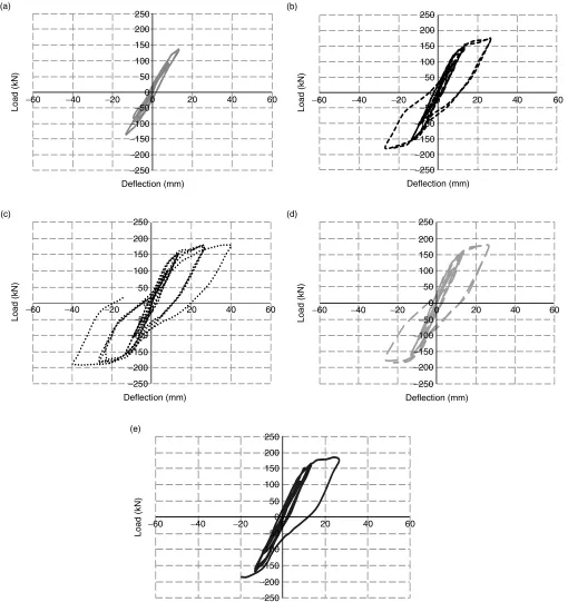
3.2. Shear Link Spacing Increase SI =50%
The results for this case are presented in Figure 8 and Table 3. For convenience, the results also include those corresponding to the Control Column (CC) specimen, i.e. the one with no fibres and no stirrup spacing increase. It was found that when the spacing between stirrups was increased, the addition of substitutive steel fibres increased the strength of the columns gradually. The same was observed with regards to ductility, however, the highest ductility was observed with
Vf = 1.5%, beyond which additional fibres led to reduced ductility. The number of cycles achieved before failure follows a similar trend.
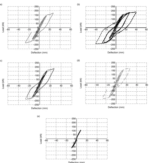
3.3. Shear Link Spacing Increase SI =100%
The results are presented in Figure 9 and Table 4 for SFRC columns with SI =100%, which shows that the inclusion of fibres increased the strength of the SFRC columns. Furthermore, the ductility also increased significantly with the maximum ductility found on columns with Vf = 2%. It can be concluded that the addition of fibres enhances ductility and the number of cycles (i.e. energy dissipation). The efficiency of the fibres increases when they are added to compensate for the reduction of shear links. Conversely, adding high amounts of fibres in addition to sufficient quantities of shear links can reduce rather than enhance ductility. This suggest that a situation similar to the one experienced in reinforced-concrete design when increasing flexural reinforcement beyond a certain threshold (i.e. balanced section) leads to an increase in strength but a reduction in ductility.
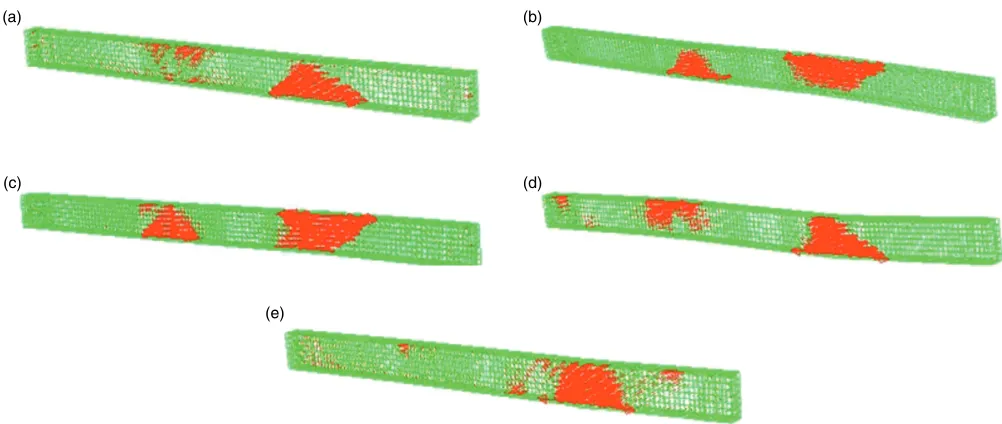
3.4. Principal Strain Vectors and Crack Patterns
The principal strain vectors can be adopted to conveniently indicate the cracking pattern for the columns. The results are presented in Figures 10 to 12. It was found that, in most of the analysed, the failure was due to the cracks opening in these two regions: (i) intermediate support; and (ii) the region where the lateral cyclic load is applied. The extent of strain vectors as shown in Figure 10(e) marks the cracking pattern of the column Vf = 2.5% that exhibited brittle (i.e. shear failure). In the columns with SI = 50%, the addition of fibres delays the crack propagation and facilitates moment redistribution, thus allowing the SFRC columns to develop a second plastic hinge at the intermediate (a) −60 −250 −200 −150 −100 −50 0 50 100 150 200 250
−40 −20 0
Deflection (mm)
Load (kN)
Load (kN)
20 40 60
Vf= 0% Vf= 1% Vf= 1.5% Vf= 2% Vf= 2.5%
(b) −60 −250 −200 −150 −100 −50 0 50 100 150 200 250
−40 −20 0
Deflection (mm)
20 40 60
Vf= Control column Vf= 0% Vf= 1% Vf= 1.5% Vf= 2% Vf= 2.5%
Load (kN) (c) −40 −250 −200 −150 −100 −50 0 50 100 150 200 250
−20 0
Deflection (mm)
20 40 60
[image:8.595.47.284.54.613.2]Vf= Control column Vf= 0% Vf= 1% Vf= 1.5% Vf= 2% Vf= 2.5%
Figure 6.(a) Load-deflection hysteresis loops for SFRC columns with SI=0% (b) Load-deflection hysteresis loops for SFRC columns with SI=50% (c) Load-deflection hysteresis loops for
−60 (a)
−250
−200
−150
−100
−50 0 50 100 150 200 250
−40 −20 0
Deflection (mm)
Load (kN) 20 40 60 −60
(b)
−250
−200
−150
−100
−50
0 50 100 150 200 250
−40 −20 0
Deflection (mm)
Load (kN)
20 40 60
−60 (c)
−250
−200
−150
−100
−50 0 50 100 150 200 250
−40 −20 0
Deflection (mm)
Load (kN)
20 40 60
−60 (e)
−250
−200
−150
−100
−50 0 50 100 150 250
200
−40 −20 0
Deflection (mm)
Load (kN)
20 40 60
−60 (d)
−250
−200
−150
−100
−50 0 50 100 150 200 250
−40 −20 0
Deflection (mm)
Load (kN)
[image:9.595.47.559.52.607.2]20 40 60
Figure 7.Load-deflection curves for SFRC columns with SI=100% for: (a)Vf= 0%; (b)Vf= 1%; (c)Vf= 1.5%; (d) Vf= 2%; and (e) Vf= 2.5%
support. In contrast, the column with no fibres (i.e. Vf = 0%) fails with intensive cracking at the mid-span of the second span of the column. In addition, for the column with SI= 50%, the cracking is larger in the region where the lateral load is applied. Based on the cracking patterns observed, it is concluded that even under the severe loading type of reversed-cyclic loading (e.g. the
It must be borne in mind that since the crack patterns of Figures 10 to 12 were produced by using principal strain vectors and when these were highly clustered, this was taken to indicate the severity and extent of cracking. Nevertheless this only provides a schematic representation of cracks, while
load-deflection curves provide more definitive results especially in terms of strength and ductility which can be used to determine the failure mode more accurately. For this reason, ductility and energy absorption ratios as well as number of cycles were examined as discussed next.
−60 (a)
−250
−200
−150
−100
−50 0 50 100 150 200 250
−40 −20 0
Deflection (mm)
Load (kN)
20 40 60 −60
(b)
−250
−200
−150
−100
−50 0 50 100 150 200 250
−40 −20 0
Deflection (mm)
Load (kN)
20 40 60
−60 (c)
−250
−200
−150
−100
−50 0 50 100 150 200 250
−40 −20 0
Deflection (mm)
Load (kN)
20 40 60
−60 (e)
−250
−200
−150
−100
−50 0 50 100 150 250
200
−40 −20 0
Deflection (mm)
Load (kN)
20 40 60
−60 (d)
−250
−200
−150
−100
−50 0 50 100 150 200 250
−40 −20 0
Deflection (mm)
Load (kN)
[image:10.595.46.556.63.604.2]20 40 60
Figure 8.Load-deflection curves for Case for SFRC columns with SI =50% for: (a)Vf= 0%; (b)Vf= 1%; (c)Vf= 1.5%; (d) Vf= 2%; and (e)
3.5. Comparative Study with Control Specimen using Non-Dimensional Ratios
In order to make overall conclusions, figures encompassing key indicators of structural behaviour under cyclic loading and covering the practical range of fibres were prepared and are discussed next. The basic
idea is to depict the change in the ductility ratio, energy absorption and number of cycles completed before failure. The comparative study was developed by working out the ratio between these parameters at given
Vf and SI values to their corresponding values for the control column specimen (i.e. the one with no fibres and
−60 (a)
−250 −200 −150 −100 −50 0 50 100 150 200 250
−40 −20 0
Deflection (mm)
Load (kN)
20 40 60 −60
(b)
−250 −200 −150 −100 −50 0 50 100 150 200 250
−40 −20 0
Deflection (mm)
Load (kN)
20 40 60
−60 (c)
−250 −200 −150 −100 −50 0 50 100 150 200 250
−40 −20 0
Deflection (mm)
Load (kN)
20 40 60
−60 (e)
−250 −200 −150 −100 −50 0 50 100 150 250
200
−40 −20 0
Load (kN)
20 40 60
−60 (d)
−250 −200 −150 −100 −50 0 50 100 150 200 250
−40 −20 0
Deflection (mm)
Deflection (mm)
Load (kN)
[image:11.595.47.555.58.609.2]20 40 60
Figure 9.Load-deflection curves for SFRC columns with SI for: SI =50% for: (a)Vf= 0%; (b)Vf= 1%; (c)Vf= 1.5%; (d) Vf= 2%; and
full conventional shear reinforcement). By normalising the results in this manner, overall conclusions were made on the potential of fibres to compensate for reduction in conventional transverse reinforcement.
3.5.1. Ductility ratio
Figure 13(a) shows the ratio between the ductility ratio in each column µ and that in the control column specimen (µ0) for the three stirrup spacing increases considered. The highest ductility ratio improvements for columns with SI = 0%, 50% and 100% were reached when fibres were provided at Vf = 1%, 1.5% and 2%, respectively. These optimum fibre dosages also
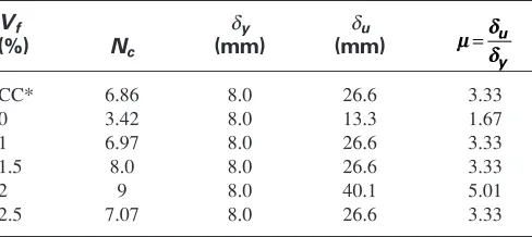
[image:12.595.45.288.88.187.2]represent the thresholds beyond which any additional fibres actually lead to less rather than more ductility as discussed earlier. It was also found that the minimum amount of fibres needed to restore the ductility levels to those associated with the control column specimen – i.e. the one with SI=0% and Vf=0% – is Vf=1% for both column cases with SI = 50% and 100% [this was obtained from Figure 13(a) by identifying Vf values corresponding to µ/µ,0=1]. It is interesting to note that the drop in ductility ratio occurs at lower fibre dosages in the columns with smaller stirrup spacing increases. This suggests that the provision of high amounts of fibres in addition to high amounts of conventional transverse reinforcement leads to a brittle structural response. The reduction in ductility is a consequence of the fibres (added at high dosages) and stirrups (also added in high amounts) controlling crack opening which leads to a stiffer response, i.e. causing the columns to deflect less. Conversely, adding increasing amounts of fibres is more suited to situations where there is a high Table 2. Results summary from load-deflection
curves for SFRC columns with SI= 0%
Vf δy δu
(%) Nc (mm) (mm)
0 6.86 8.0 26.6 3.33
1 10.46 8.0 40.0 5.01
1.5 7.97 8.0 26.6 3.33
2 6.86 8.0 26.6 3.33
2.5 3.15 8.0 8.3 1.04
µµ δδ δδ = u
y
Table 3. Results summary from load-deflection curves for SFRC columns with SI= 50% (* CC is the control column specimen with Vf=0% and SI =0%)
Vf δy δu
(%) Nc (mm) (mm)
CC* 6.86 8.0 26.6 3.33
0 4.95 8.0 13.3 1.67
1 7.75 8.0 26.6 3.33
1.5 9.91 8.0 40.0 5.01
2 7.75 8.0 26.6 3.33
2.5 6.75 8.0 26.6 3.33
µµ δδ δδ = u
y
Table 4. Result summary from load-deflection curves for SFRC columns with SI= 100% (* CC is the
control column specimen with Vf=0% and SI=0%)
Vf δy δu
(%) Nc (mm) (mm)
CC* 6.86 8.0 26.6 3.33
0 3.42 8.0 13.3 1.67
1 6.97 8.0 26.6 3.33
1.5 8.0 8.0 26.6 3.33
2 9 8.0 40.1 5.01
2.5 7.07 8.0 26.6 3.33
µµ δδ δδ = u
y
(a)
(b)
(c)
[image:12.595.42.291.261.370.2](e) (d)
Figure 10.Principal strain vectors for Case Study 2(b) column with SI =50% for: (a)Vf= 0%; (b)Vf= 1%; (c)Vf= 1.5%; (d)
[image:12.595.44.288.444.553.2]reduction in conventional reinforcement (so in effect the fibres need some room to provide ductility and combining excessive amounts of fibres with sufficient conventional reinforcement should be avoided).
3.5.2. Energy absorption ratio
The ratio between the energy absorption capacity in each column (Ea) and that in the control column specimen (Ea,0) is presented in Figure 13(b). The results show that
the addition of steel fibres has led to a significant increase in the energy absorption ratio compared to the
original levels associated with the control specimen. The highest energy absorption enhancement for columns with SI= 0%, 50% and 100% were found to be at Vf= 1%, 1.5% and 2%, respectively. It was also found that the minimum amounts of fibres needed to restore the energy absorption levels associated with the control column specimen are Vf=0.25% and 0.5% for columns with SI=50% and 100%, respectively. Similarly to the ductility ratio patterns observed earlier, it was found that adding fibres beyond certain thresholds leads to a decrease in energy absorption. Nevertheless, the
(a) (b)
(c)
(e)
[image:13.595.39.551.60.278.2](d)
Figure 11.Principal strain vectors for Case Study 2(b) column with SI =50% for: (a)Vf= 0%; (b)Vf= 1%; (c)Vf= 1.5%; (d) Vf= 2%; and
(e) Vf= 2.5%
(a) (b)
(c)
(e)
(d)
Figure 12.Principal strain vectors for Case Study 2(b) column with SI =50% for: (a)Vf= 0%; (b)Vf= 1%; (c)Vf= 1.5%; (d) Vf= 2%; and
[image:13.595.47.548.338.550.2]resulting reduced energy was still sufficient to restore the energy absorption levels associated with the control column specimen, which could be useful in situations where high fibre amounts are needed for strength enhancement purposes. Interestingly, again similarly to
the ductility ratio trends, it was found that the drop in the energy absorption ratio starts at lower fibre dosages in the columns with smaller stirrup spacing increases. Thus it can be concluded that fibres should be added to substitute reduced conventional transverse reinforcement rather than being combined with sufficient amounts of the latter.
3.5.3. Number of cycles ratio
Figure 13(c) depicts the effect of adding fibres and increasing the links spacing on the number of cycles completed before failure. The results are normalised by determining the ratio between the maximum number of cycles reached before failure in each column Nc and those related to the control column specimen (Nc,0). The
results show that the increase in links spacing leads to a significant reduction in the number of cycles when no fibres are added (i.e. increased brittleness) as one would expect. On the other hand, when steel fibres were added, the number of cycles has increased as a result. The largest Nc for the parametric studies was achieved for the column with SI=0% at fibre dosage Vf=1%. In fact, in most cases the original number of cycles with
Vf = 0% and SI = 0% was restored and exceeded (i.e.
Nc/Nc,o>1.0). However, there was an exception to this,
namely for columns with no stirrup spacing increase and fibres with Vf=2% ∼2.5% used. The general trends are similar to the ones observed for ductility and energy absorption. The optimum fibre dosages were found to be at Vf = 1%, 1.5%, and 2% for columns with
SI=0%, 50% and 100%, respectively (again, excessive fibres beyond these limits lead to reduction in the number of cycles achieved before failure). The data also confirms that adding high fibre amounts combined with no spacing increases leads to a less ductile behaviour.
4. CONCLUSIONS
SFRC statically-indeterminate (two-span continuous) columns were studied under reversed-cyclic loading by means of NLFEA using ABAQUS software. The numerical predictions were initially calibrated against existing experimental data. The research work principal aim was to examine the potential of steel fibres to substitute a reduction in conventional transverse reinforcement. To achieve this, the spacing between shear links was relaxed while fibres were added (the spacing between the links was increased by 50% and 100% while the fibre volume fraction was increased to 1%, 1.5%, 2% and 2.5%). This is useful in situations where significant amounts of conventional transverse stirrups is required (e.g. in seismic design), which results in congestion and construction challenges. The critical factor in the seismic response is the reversed-(a)
0.00
0 0.5 1 1.5
Vf(%)
2 2.5 3
0.20 0.40 0.60 0.80
µ
/
µ
,0
1.00 1.20 1.40 1.60
SI = 0% SI = 50% SI = 100%
(b)
0
0 0.5 1 1.5
Vf(%)
2 2.5 3
1 2 3 4
Ea
/Ea,0
5 6 7 8
(c)
0.40
0 0.5 1 1.5
Vf(%)
2 2.5 3
0.60 0.80 1.00
Nc/Nc,0
1.20 1.40 1.60
SI = 0% SI = 50% SI = 100%
[image:14.595.49.290.57.553.2]SI = 0% SI = 50% SI = 100%
Figure 13.(a) Ratio between the ductility ratio in each column and that in the control column specimen (SI =0%, Vf= 0%) versus
fibre volume fraction (b) Ratio between the energy absorption in each column and that in the control column specimen (SI =0%,
Vf= 0%) versus fibre volume fraction (c) Ratio between the
maximum number of cycles before failure in each column and that in the control column specimen (SI =0%, Vf= 0%) versus fibre
cyclic nature of the load, which is examined in the present research work. The present research work is an attempt to understand the structural response of SFRC statically-indeterminate columns under cyclic loads using the case study examined. Nevertheless, additional column configurations need to be examined along with further experimental tests and field calibrations and crucially input from practicing engineers before the findings can be adopted for design.
Based on the results obtained, it can be concluded that the strength, ductility and energy absorption capacity of the columns improved with the addition of fibres. Interestingly, it was also found that ductility (and energy absorption) of the column decreases once the fibres added exceed an optimum threshold. For the column with SI = 0%, 50% and 100%, the optimum fibre volume fraction values obtained are Vf = 1%,
Vf=1.5%, and Vf= 2% respectively. This is similar to the “over-reinforced” response experienced in conventional RC design when the main reinforcement is increased beyond a certain threshold (i.e. “balanced section”) leadings to increase in strength but reduction in ductility. In the present SFRC case, this anomaly is attributed to the fact that fibres provided at high amounts lead to a stiffer response and hence cause the column to deflect less. The energy absorption ratio calculated also shows a similar pattern to that observed for the ductility ratio. It is interesting to note that the drop in ductility ratio starts at lower fibre dosages in the columns with smaller stirrup spacing increases. This suggests that the addition of high amounts of fibres in addition to high amounts of conventional transverse reinforcement leads to a brittle structural response. Conversely, adding increasing amounts of fibres is more suited to situations where there is a high reduction in conventional reinforcement. So in effect there is a trade-off between the two types of reinforcement and combining excessive amounts of fibres with sufficient conventional reinforcement is counterproductive. Thus, it can be concluded that the addition of fibres is more efficient when the stirrups spacing is increased. Further investigations are needed on other column arrangements to ascertain the optimum fibre dosages. Moreover, it was found that steel fibres help control crack propagation especially in the section between the intermediate support and the section where the lateral cyclic load is applied. Most of the cracking develops at two main regions, which are intermediate support and the section where the lateral load is applied.
In summary, it can be concluded that steel fibres enhance the strength, ductility and energy absorption capacity of statically-indeterminate columns, which is particularly useful in seismic design. However, in order
to realise these benefits the fibres should be provided in optimum – rather than excessive – amounts. Furthermore, the cracking patterns observed in SFRC columns are better than that in the column with no fibres. Thus, the use of steel fibres enhances he cyclic responses of the columns and provides a better strength, ductility, energy absorption as well controlling crack propagation.
REFRENCES
Abbas, A.A., Syed Mohsin, S.M., Cotsovos, D.M. and Ruiz-Teran, A.M. (2014a). “Nonlinear analysis of statically-indeterminate SFRC columns”, Structural Concrete, Vol. 15, No. 1, pp. 94–105. Abbas, A.A., Syed Mohsin, S.M., Cotsovos, D.M. and Ruiz-Teran, A.M. (2014b). “Shear behaviour of steel-fibre-reinforced concrete simply supported beams”, Proceedings of the ICE
-Structures and Buildings, (Accessed 31/03/2014).
Abbas, A.A., Syed Mohsin, S.M., Cotsovos, D.M. and Ruiz-Teran, A.M. (2014c). “Seismic response of steel fibre reinforced concrete beam-column joints”, Engineering Structures, Vol. 59, pp. 261–283.
Abbas, A.A., Syed Mohsin, S.M. and Cotsovos, D.M. (2012). “Steel-fibre-reinforced concrete beams under cyclic loads”, Proceedings
of the 8thRILEM International Symposium on Fibre Reinforced
Concrete: Challenges and Opportunities BEFIB2012,
Guimaraes, Portugal, pp. 227–228.
Abbas, A.A., Syed Mohsin, S.M. and Cotsovos, D.M. (2010a). “Numerical modelling of fibre-reinforced concrete”, Proceedings of the International Conference on Computing in Civil and
Building Engineering icccbe 2010, Nottingham, UK.
Abbas, A.A., Syed Mohsin, S.M. and Cotsovos, D.M. (2010b). “A comparative study on modelling approaches for fibre-reinforced concrete”, Proceedings of the 9thHSTAM International Congress
on Mechanics,Limassol, Cyprus, pp. 12–14.
Abaqus (2007). Version 6.7 Documentation, http://www.simulia.com/services/training/V67-Introduction-DEMO/AbaqusV67Intro.htm.
Bayasi, Z. and Gebman, M. (2002). “Reduction of lateral reinforcement in seismic beam-column connection via application of steel fibres”, ACI Structural Journal, Vol. 99, No. 6, pp. 772–780.
Barros, J.A. and Figueiras, J.A. (1999). “Flexural behaviour of SFRC: testing and modelling”, Journal of Materials in Civil
Engineering, ASCE, Vol. 11, No. 4, pp. 331–339.
Barros, J.A. and Figueiras, J.A. (2001). “Model for the analysis of steel fibre reinforced concrete slabs on grade”, Computers and
Structures, Vol. 79, No. 1, pp. 97–106.
Bencardino, F., Rizzuti, L., Spadea, G. and Ramnath, N. (2008). “Stress-strain behaviour of steel fibre-reinforced concrete in compression”, Journal of Materials in Civil Engineering,ASCE, Vol. 20, No. 3, pp. 255–262.
Eurocode 2 (2004). Design of Concrete Structures - Part 1-1:
General Rules and Rules for Buildings, BSI, London, UK.
Eurocode 8 (2004). Design of Structures for Earthquake Resistance
- Part 1: General Rules, Seismic Actions and Rules for Buildings,
BSI, London, UK.
Campione, G., La Mendola, L. and Papia, M. (2006). “Shear strength of steel fibre reinforced concrete beams with stirrups”, Structural
Engineering and Mechanics, Vol. 24, No. 1, pp. 107–136.
Campione, G. and Mangiavillano, M.L. (2008). “Fibrous reinforced concrete beams in flexure: Experimental investigation, analytical modelling and design considerations”, Engineering Structures,
Vol. 30, pp. 2970–2980.
Cho, S.H. and Kim, Y.I. (2003). “Effects of steel fibres on short beams loaded in shear”, ACI Structural Journal,Vol. 100, No. 6, pp. 765–774.
El-Niema, E.I. (1991). “Reinforced concrete beams with steel fibres under shear”, ACI Structural Journal, Vol. 88, No. 2, pp. 178–183.
Hannant, D.J. (1978). Fibre Cements and Fibre Concretes, John Wiley & Sons, New York, USA.
Hughes, G. and Spiers, D.M. (1982). An Investigation on the Beam
Impact Problem, Technical Report 546, Cement and Concrete
Association, Buckinghamshire, UK.
Kotsovos, G., Zeris, C. and Kotsovos, M. (2007). “The effect of steel fibres on the earthquake-resistant design of reinforced concrete structures”, Materials and Structures, Vol. 40, No. 2, pp. 175–188.
Kwak, Y.K., Eberhard, M.O., Kim, W.S. and Kim, J. (2002). “Shear strength of steel fibre-reinforced concrete beams without stirrups”, ACI Structural Journal,Vol. 99, No. 4, pp. 530–538. Lok, T.S. and Pei, J.S. (1998). “Flexural behaviour of steel
fibre-reinforced concrete”, Journal of Materials in Civil Engineering,
ASCE, Vol. 10, No. 2, pp. 86–97.
Lok, T.S. and Xiao, J.R. (1999). “Flexural strength assessment of steel fibre-reinforced concrete”, Journal of Materials in Civil
Engineering, ASCE, Vol. 11, No. 3, pp. 188–196.
Mansur, M.A., Ong, K.C.G., and Parasiivam, P. (1986). “Shear strength of fibrous concrete beams without stirrups”, Journal of
Structural Engineering, ASCE, Vol. 112, No. 9, pp. 2066–2079.
Narayanan, R. and Darwish, I.Y.S. (1987). “Use of steel fibres as shear reinforcement”, ACI Structural Journal, Vol. 84, No. 3, pp. 216–227.
RILEM Technical Committees (2000). “RILEM TC 162-TDF: Test and design methods for steel fibre-reinforced concrete, recommendation: σ− εdesign method”, Materials and Structures,
Vol. 33, No. 2, pp. 75–81.
RILEM Technical Committees (2003). “RILEM TC 162-TDF: test and design methods for steel fibre-reinforced concrete, final
recommendation: σ− εdesign method”,Materials and Structures,
Vol. 36, No. 8, pp. 560–567.
Sharma, A.K. (1986). “Shear strength of steel fibre reinforced concrete beams”, ACI Journal Proceedings, Vol. 83, No. 4, pp. 624–628.
Swamy, R.N. and Al-Ta’an, S.A. (1981). “Deformation and ultimate strength in flexure of reinforced concrete beams made with steel fibre concrete”, ACI Journal Proceedings, Vol. 78, No. 3, pp. 395–405.
Swamy, R.N. and Bahia, M. (1985). “The effectiveness of steel fibres as shear reinforcement”, Concrete International, Vol. 7, No. 3, pp. 35–40.
Syed Mohsin, S.M. (2012). Behaviour of Fibre-Reinforced Concrete
Structures under Seismic Loading, PhD thesis, Imperial College
London, London, UK.
Tlemat, H., Pilakoutas, K. and Neocleous, K. (2006). “Modelling of SFRC using inverse finite element analysis”, Materials and
Structures, Vol. 39, No. 2, pp. 221–233.
Zheng, Y., Robinson, D., Taylor, S. and Cleland, D. (2012). “Non-linear finite-element analysis of punching capacities of steel-concrete bridge deck slabs”, Structures and Buildings,Vol. 165, No. 5, pp. 255–259.
NOTATION
Ea energy absorption
Ea,0 energy absorption of the control specimen
L/d fibre aspect ratio
N axial force applied on the column
Nc number of cycles completed before failure
Nu compression resistance of the column provided by concrete
P lateral reversed-cyclic load
SI stirrup spacing increase
Py load at yield
Pmax load-carrying capacity
Pmax,0 load-carrying capacity of the control
specimen
Pu ultimate load
δy deflection at yield
δu ultimate deflection
µ ductility ratio
µ,0 ductility ratio of the control specimen
τd bond stress between concrete and steel fibres