RFID and Keypad Based Door Lock System using Microcontroller
Zar Kyi Win
1Aung Zaw Oo
21,2
Department of Electrical Power Engineering
1,2Technological University (Lashio), Myanmar
Abstract— In this paper, it is going to develop an RFID and keypad based door lock system using PIC 16F887 microcontroller. It has become a standard feature on many different types of buildings and homes and they are becoming popular every day to develop effective electronic devices which provided security. The RFID door lock system is a lock that is simple to install and allow the user to easily lock and unlock doors. It will contain a RFID reader/writer and a magnetic door lock for simple use. The entire user will need an RFID tag to be able to unlock and lock the door. The present state is notified by the LCD display to the user. A LED is used to let the user know when the door is locked in actual fact. The components are included in the module that is small and compact. This is also left the consumer with the option of using their original lock and key if they choose. All in all, this RFID and keypad door lock should be a simple and cost effective upgrade to the average consumer’s security and convenience.
Keywords: RFID, PIC 16F887 Microcontroller, LCD
Display, Keypad
I. INTRODUCTION
The Basic necessity of security can be attained by designing various door locks such as mechanical locks or electrical locks. These kinds of door locks are designed with one or more keys, but for locking a large area various locks are needed. Generally, traditional locks are heavy and that are not strong as they can damage simply by using some tools. Electronic locks are better over mechanical locks, to resolve the security problems that are connected with the mechanical locks. RFID Based Door Lock System has become a standard feature on many different types of buildings and homes. And they are becoming popular every day to develop effective electronic devices which provided security. Home security has been a major issue because of the increase in crime rate and everybody wants to take proper action to prevent unauthorized user.
RFID system is to carry data on a transponder (tag) that can be retrieved with a transceiver through a wireless connection. RFID based door lock system presented in this work is based on PIC 16F887 microcontroller. The system can be installed at the entrance of a secured environment to prevent and unauthorized individual access. The system functions in real time as when the user put the tag in contact with the reader, the door open and the information is display on LCD and if the information is not correct the alarm will start ringing. This system is approached by the combination of hardware and software.
II. HARDWARE COMPONENTS
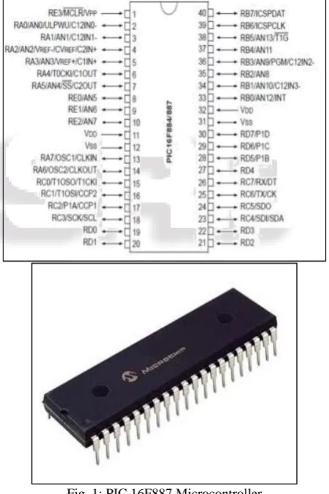
A. PIC 16F887 Microcontroller
Programmable Intelligent Computer (PIC 16F887) is a family of microcontrollers made by Microchip Technology, derived from thePIC1650 originally developed by General
[image:1.595.308.549.281.642.2]Instrument's Microelectronics Division. The name PIC initially referred to Peripheral Interface Controller, then it was corrected as Programmable Intelligent Computer. Early models of PIC had read-only memory Technology using a 1200 nanometer process (ROM) or field-programmable EPROM for program storage, some with provision for erasing memory. All current models use flash memory for program storage, and itself. Program memory and data memory are separated. Data memory is 8-bit, 16- bit, and, in latest models, 32-bit wide. Program instructions vary in bit-count by family of PIC, and may be 12, 14, 16, or 24 bits long. The instruction set also varies by model, with more powerful chips adding instructions for digital signal processing functions.
Fig. 1: PIC 16F887 Microcontroller
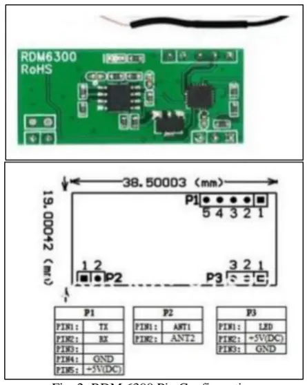
B. RFID Reader (RDM6300)
Fig. 2: RDM 6300 Pin Configuration
The electronic module also perform a number of security functions such as encryption/decryption and user authentication, and another critical function called anti-collision, which enable a reader to communicate with multiple tags simultaneously. The reader can send information in two directions: it can read information from a tag and send it to the PC, or it can read information from the PC and to an RFID tag.
C. RFID Card
[image:2.595.317.538.66.237.2]This is a basic RFID tag used for presence sensing etc. it works in the 125 kHz RF range. These tags come with a unique 32-bit ID and are not re-programmable. Card is blank on one side, smooth, and mildly flexible.
Fig. 3: RFID Card
D. 16x2 LCD Display
The LCD display module includes 2x16-character lines and a 16-pin connector. Each character position is identified by its row number (1 or 2), and its column number (from 1 to 16). The LCD interface offers many ways to easily create a user interface to display text messages and other application related information, whilst using very few internal hardware resources.
Fig. 4: 16x2 Line LCD Display
E. 4x4 Keypad
This 4x4 matrix keypad has 16 built-in pushbutton pressed states. In the keypad, the Propeller sets all the column lines to input and all the row lines to input. Then, it picks a row and sets it high. After that, it checks the column line one at a time. If the column connection stays low, the button on the row has not been pressed. If it goes high, the microcontroller knows which row and which column.
Fig. 5: 4x4 Matrix Keypad
F. MAX 232 IC
[image:2.595.59.278.512.645.2]MAX 232 is widely known IC used for establishing serial communication between Microcontrollers and Personal Computers (PC). This IC is use to convert TTL/CMOS logic levels to RS232 logic level during the process of serial communication. Usually a Microcontroller operates at TTL (Transistor Transistor Logic) of about 0-5 V whereas a PC works on RS232 standards that is (-25 to +25V). So it is not possible to interface a PC directly with a Microcontroller and this is exactly where a MAX232 IC comes into Play.
[image:2.595.374.483.618.756.2]G. LM 7805 IC Circuit
[image:3.595.366.484.66.212.2]7805 is a voltage regulator integrated circuit (IC) which is widely used in electronic circuits. They provide a constant output voltage for a varied input voltage. The 7805 IC is an iconic regulator IC that finds its application in most of the projects. 7805 will provide a +5V output voltage.
Fig. 7: LM7805 IC
H. PC 817
PC 817 is also known as optocoupler. It consists of Infra-Red Emitting Diode (IRED). This IRED is coupled to a photo transistor optically and not electrically. It is closed in a four (4) pin package. This package is usually available in two different forms. The first one is wide lead (Pb) spacing option and the second one is SM gulling lead from option
Fig. 8: PC 817
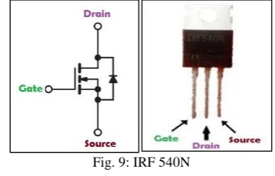
I. IRF 540N
[image:3.595.92.244.140.284.2]IRF 540N is basically an N-channel power Metal Oxide Silicon Field Effect Transistor (MOSFET) and operates in enhancement mode, so the Drain and Source pins will be left open when there is no voltage applied to the gate pin. When a gate voltage is applied these pins gets closed.
Fig. 9: IRF 540N
J. 2N2222A
2N2222A is a common NPN bipolar junction transistor (BJT) used for general purpose low-power amplifying or switching applications. It is designed for low to medium current, low power, medium voltage, and can operate at moderately high speeds.
Fig. 10: 2N2222A
K. Door Lock
[image:3.595.51.534.349.484.2]Door lock is used to lock and unlock using a 12V power supply. These Locks are basically electromagnets: they are made of a big coil of copper wire with an armature (a slug of metal) in the middle. When the coil is energized, the slug is pulled into the center of the coil and the cabinet/door is unlocked. When 12V power is removed, an internal spring pushes the slug out and the cabinet/door is locked again. This means that when activated with up to 12VDC, the solenoid moves and when the voltage is removed it springs back to the original position, which is quite handy.
Fig. 11: Door Lock
L. Buzzer
[image:3.595.358.497.536.659.2]A buzzer is an audio signaling device, which may be mechanical, electromechanical, or piezoelectric. Typical uses of buzzers include alarm device, timers, and confirmation of user input such as mouse click or keystroke.
Fig. 12: Buzzer
III. IMPLEMENTATION OF THE SYSTEM
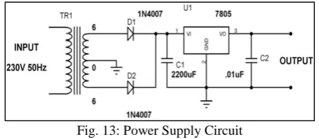
A. Power Supply
[image:3.595.67.261.562.686.2]better 5 volt output, a capacitor is usually added to the circuit, going between the 5 volt output and ground (GND).
Fig. 13: Power Supply Circuit
B. Software Implementation of RFID Reader and RFID
[image:4.595.320.534.90.220.2]When a Card (tag) is brought near the RFID reader, it will read its tag number and give output via TX terminal and it tries to communicate with the tag, receives the data and decodes it. Finally it sends the data over the Tx line. The UART output will be 12 ASCII data, among these first 10 will be tag number and last 2 will be XOR result of the tag number which can be used for error testing. The RFID tag number is 0200E9C77E; output of RDM6300 Reader will be 0200E9C77E52 where 52 is 02 xor 00 xor E9 xor C7 xor 7E. A checksum is a count of the number of bits in a transmission unit that is included with the unit so that the receiver can check to see whether the same number of bits arrived. If check error, the tag reading is error.
Fig. 14: Software Implementation of RFID Reader and RFID
C. RDM6300 RFID Reader Interfacing with PIC
Microcontroller
Microcontroller board is powered from an external source like DC supply. Microcontroller board has 5V regulator built in. 5V Output is available from voltage regulator. The 5V out is feed to the RFID reader which powers the module. So to interface PIC microcontroller it should connected pin number one of header P1 (TX line) of RFID module which transmit data pin to pin number RC7 (RX line) of PIC16F887 microcontroller. TX line of microcontroller and Rx line of RFID Reader are unused. And then, connected 5 volt and ground to RFID module. This will turns on the Buzzer and LED. Meantime RFID tag data will be sending to microcontroller via UART. RDM6300RFID Reader Module
can be directly interfaced with 5V of PIC microcontrollers using UART communication.
Fig. 15: RDM6300 RFID Reader Interfacing with PIC Microcontroller
D. LCD Display Interfacing with PIC Microcontroller
Data and Command Information are sending to LCD through same data lines (DB0 – DB7) which are multiplexed using RS (Register Select) pin of LCD. When RS is HIGH LCD treats DB0 – DB7 data pins information as Data to be displayed and when it is LOW LCD treats it as Command Information. Enable (E) input of the LCD is a control line to inform the LCD that data has been sent. HIGH (5V) Voltage Level in the Enable (E) pin tells the LCD that DB0–DB7 contains valid information. The inputs signals R/W (Read or Write) determine whether data is written to or read from the LCD.
Fig. 16: LCD Display Interfacing with PIC Microcontroller
E. 4x4 Matrix Keypad Interfacing with PIC Microcontroller
In a 4x4 matrix keypad, there are four rows and four columns connected to 16 push buttons switches. It may look like one needs 16 pins for the microcontroller to be connected to the matrix keypad, but practically 16 inputs of keypad interface are possible with the 8 pins of a microcontroller port. All 8 lines can be connected to the same port or different ports based on the application requirements. In fact, 8 port pins of a microcontroller are sufficient for a 4×4 keypad interface using row and column matrix connection technique by saving other 8 bits of the port.
[image:4.595.53.282.357.557.2]Fig. 17: LCD Display Interfacing with PIC Microcontroller
F. LED Indicator
[image:5.595.321.534.67.211.2]This circuit has been used three LED indicator for user mode (supervisor mode), normal operate, and error (or) pass. Red, yellow, blue, and green are the basic colour of LED. Maximum forward drop of red, yellow, blue, and green are 2.3, 2.8, 3.4, and 3.4V respectively. In this circuit, minimum forward voltage drop (red) is used. By using that voltage, LED will not be destroyed if other colours are used instead of red.
Fig. 18: Circuit Diagram of LED Indicator
IV. OPERATION AND RESULT OF THE SYSTEM
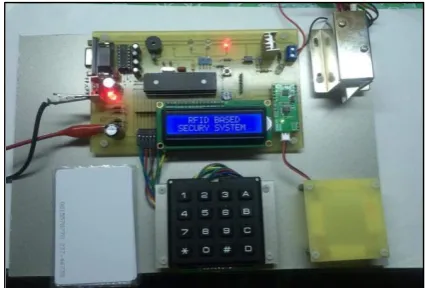
If it wants RFID tag to enroll, it must enter admin mode "#" key from the keypad and enter password. And the LCD display texts message 'Press A, B, C, D'. If it wants RFID tag to enroll, press 'A' key and must be added to each tag. Every the tag enrolled, and then it must enter 'A' key. If it wants to delete all enrollment RFID tag, press reset and enter 'D' key. After all, enrollment RFID tag placed on the RFID reader and it read the data and through reader its code send to the controller's EPROM which access with the controller match and receives code with store code if the code is same then the security system is authorized to use and access the data. After access control system the information is display on LCD and if the information is not correct the alarm will start ringing. If uploading is doing well, we will see the glowing of LED. It means the system is prepared to read the tag. Now, bring the tag near to RFID reader. If tag ID matches with the ID in the code, lock will open for five seconds. It closes manually after five seconds. Glowing of LED indicate that the lock is open. Glowing of caution LED means that we are using the wrong tag.
Fig. 19: Test Result of Constructed Door Lock System The range is found to be 8 to 10cm which is sufficient for the application of RFID access control. It is also found that the detection is not affected by obstructing materials between the tag and antenna. Test this system for 5cm thick cloth, cardboard and it was found that the system still functions properly.
V. DISCUSSION
RFID and keypad based door lock system is a very cheap and affordable design that allows convenience and security for users. The design is relatively small and easy enough to install with just a couple of screws. Of course, there are additional features that can be added in order to improve the system as a whole. The system is used in the places where it needs more security. It can also use to secure lockers and other protective doors. The system comprises LCD, a number keypad and the keypad are connected to the 8bit microcontroller PIC 16F887. The microcontroller is continuously monitored the keypad and LCD.
VI. CONCLUSION
RFID and keypad based door lock does not need to carry a key with user. They will no longer need to worry about losing their key or fidgeting at the door to get it open. User can also provide entry to their home for others at their discretion. User will not need to make copies of a key or leaves keys for dog walker and housekeepers, or house guests to get into their home. Rather, they will simply need to tell those people the proper code in order to gain access. With the system in place, user can also tell exactly when and how people attempted to access their home. This gives them a good idea of how secure user's house is. Further, the system's benefits are compatible size and low cost, easy to implement on any device and wireless. It is used to prevent from hacking. So, finally it can conclude that, when the person swipes with authorized RFID card, then the access control system will be granted. In the same way, when the person swipes with an unauthorized RFID card, then the data will not be loaded and access will be denied.
REFERENCES
[image:5.595.61.272.67.222.2][3] R. Weinstein, “RFID: A technical overview and its application to the enterprise,” IT Professional, vol. 7, no. 3, (2005).
[4] Daniel M. Dobkin and Steven M.
Weigand,''Environmental effects on RFID tag antennas'', California: Bulis Press, (2010).
[5] Stevan Preradovic and Nemai C. Karmakar, ''RFID reader: a review''. Monash University, Australia, (2006). [6] S.Shepard, “RFID Radio Frequency Identification”,
USA, ISBN:0-07-144299-5, (2005).