Structural Design and Weight Optimization of a Wind Tower
Pavankumar P Mohare
Department of Mechanical Engineering
Nitte Meenakshi Institute of Technology, Visvesavarayya Technological University, Banglaore - 560064
Abstract— The wind turbines are the most efficient renewable energy source amongst. They convert the wind energy into electrical power. Wind tower is most important component of the wind farm. All the components of the wind tower mounted on the wind tower, so it should sustain all the loads without collapse. Most of the wind tower will fail due to its self-weight and operating speed of turbine rotor. Material density of the wind tower will perform major part of the failure. FEA analysis with working loads on wind tower of different materials will help to find proper material for wind tower. ANSYS 14.5 workbench is used for Modeling and solution.
Key words: Wind Turbine Tower, Wind Turbine Tower Load, Finite Element Analysis, Modal Dynamic Analysis
I. INTRODUCTION
Requirement of the energy increases as the economy of the country grows. The environmental friendly renewable sources of energy are used for power generation. One of these renewable sources of energy is wind. Wind energy is easily available source for the power generation. Wind forms are located in most preferred place where the wind is at high altitude to get more power. The tubular structure wind tower is made by rolling the steel plate into steel tubes and fastened by welding. To easy assemblage of wind tower it partitioned into number parts and the diameter of the wind tower is gradually decreasing from bottom to top for lowering the center of gravity of wind tower.
II. FUNDAMENTALS OF WIND TOWER
The classification of wind tower depends on the kind of support that nacelle mounted, they are
Steel-towers Lattice Tubular towers Concrete towers Hybrid towers Guy-wired pole tower
[image:1.595.309.553.118.332.2]The main components of wind towers are rotor blades, nacelle with generator and hub, tower (steel/concrete), electrical installation and grid connection and foundation.
Fig. 1: Wind Farms
Wind farm failure is one of the major demerits of the energy harvesting. Leakage of the water into lower part of the foundation of the wind farm will cause failure of the foundation. During extreme wind conditions, wind tower experience the bending moment, due to this binding wind tower will fail. Due to cutout made for door opening, bottom segment shell of the tower losses its stiffness. Due to improper welding and fastening in the flange region tends to lead the uneven loading. That loading condition causes developing bending stress in the welded region that may cause failure of wind tower.
III. OBJECTIVE OF THE WORK
To achieve the successful working stability of welded flange connected steel tubular tower, throughout its life time of 20 years, by avoiding the failure due to various environmental impacts, the building static linear analysis to find safe design for corresponding load. Dynamic analysis to find initial modes and corresponding natural frequency. Weight optimization to reduce the weight and to increase the stiffness. Obtaining the safe design for low density materials by increasing the thickness of the tower shell.
IV. DESIGN PARAMETER
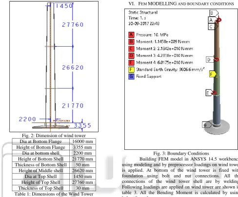
Fig. 2: Dimension of wind tower Dia at Bottom Flange 16000 mm Height of Bottom Flange 3355 mm
Dia at bottom shell 2200 mm Height of Bottom Shell 21770 mm Thickness of Bottom Shell 50 mm
Height of Middle shell 26620 mm
Dia at Top Shell 1450 mm
Height of Top Shell 27760 mm Thickness of Top Shell 30 mm Table 1: Dimensions of the Wind Tower
V. MATERIAL PROPERTIES
Wind Tower is stable under structural steel, but due its heavy weight tower will collapse lack stiffness of sustaining self-weight because of density of structural steel is high. So wind tower material properties can be replaced by low density materials. Aluminum is light in weight and has high stiffness with proper alloys and also it is non-oxidation. Carbon Fiber Reinforced Polymer is strongest composite material have very less density. Composite with proper alignment of fibers can get very high stiffness against loadings. Below table 2 shows material properties of wind tower.
Materials Structural Steel
Aluminums Al(3003)
Carbon (CRPF)
Density (g/cm3) 7.80 2.73 1.60
Ultimate Tensile strength
(MPa)
400-500 160 600
Yield Strength
(MPa) 220-250 125 110
Poission’s ratio 0.30 0.33 0.10
Young’s
Modulus (GPa) 210 69 70
Table 2: Material Properties
[image:2.595.62.283.63.489.2]VI. FEM MODELLING AND BOUNDARY CONDITIONS
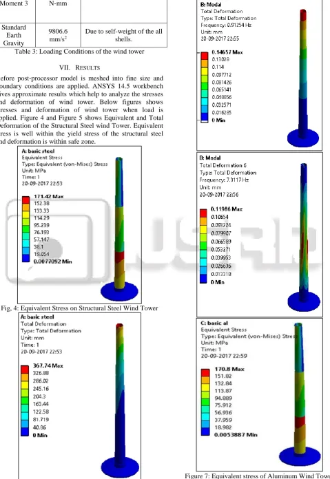
Fig. 3: Boundary Conditions
Building FEM model in ANSYS 14.5 workbench using modeling and by preprocessor loadings on wind tower is applied. At bottom of the wind tower is fixed with foundation using bolt and nut connections. All the connections of the wind tower shell are by welding. Following loadings are applied on wind tower are shown in table 3. All the Bending Moment is calculated by using below formulae.
Thrust force on rotor,
T = 0.5 ρ V2 C T π R2 Where, ρ – Air Density = 1.169 kg/m3
V – Cutout wind speed = 20 m/s CT – Thrust co-efficient
R – Rotor radius = 41m CT = 4a (1-a)
Where, a – axial induction factor = 1/3 (for ideal turbine) But, turbine converts maximum of 60% wind energy into power then, a = 0.2
Bending moment at top flange section, My,t = T x L1 Where, L1 – Length of top segment in mm.
Pressure 10 MPa
Pressure on top shell due to weight of the nacelle, turbine and rotor blade etc. Bending
Moment
1.458*109 N-mm
Bending Moment due to rotation of the Nacelle. Bending
Moment 1 2.184*10
10
N-mm
Bending Moment due to rotation of the blades. Bending
Moment 2 4.2918*10
10
N-mm
[image:2.595.56.545.66.471.2]Moment 3 N-mm
Standard Earth Gravity
9806.6 mm/s2
[image:3.595.51.531.69.766.2]Due to self-weight of the all shells.
Table 3: Loading Conditions of the wind tower
VII. RESULTS
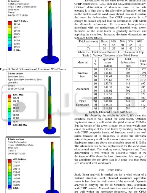
Before post-processor model is meshed into fine size and boundary conditions are applied. ANSYS 14.5 workbench gives approximate results which help to analyze the stresses and deformation of wind tower. Below figures shows stresses and deformation of wind tower when load is applied. Figure 4 and Figure 5 shows Equivalent and Total Deformation of the Structural Steel wind Tower. Equivalent stress is well within the yield stress of the structural steel and deformation is within safe zone.
Fig, 4: Equivalent Stress on Structural Steel Wind Tower
Figure 8: Total Deformation of Aluminum Wind Tower
Figure 10: Total Deformation of CFRP Wind Tower
Deformation of the wind tower of aluminum and CFRP composite is 1037.7 mm and 420.26mm respectively. Obtained deformation of aluminum tower is not safe enough; it is high above the allowable deformation of 1m. So the thickness of the wind tower should increase to sustain the tower by deformation. But CFRP composite is stiff enough to sustain applied load to deformation well within the allowable deformation. To overcome from problems associated with the replacement of material wind tower, thickness of the wind tower is gradually increased and applying the same load. Increased thickness dimensions are tabulated below table 5.
Thickness (mm) Basic 10% 20% 30% 40%
T1 50 55 60 65 70
T2 30 35 40 45 50
[image:4.595.55.552.72.724.2]Where T1 – Thickness at Bottom, T2 – Thickness at Top Table 5; Various Thickness of the Wind Tower
Material T
%
Equivalent stress (MPa)
Total deformation
(mm)
Mass (Ton)
Structural Steel
10 156.41 334 1970
20 141.86 305 1994
30 131.63 281 2022
40 120.65 252 2038
Aluminum
10 155.76 941 697
20 141.33 860 705
30 131.02 792 713
40 119.55 720 722
CFRP Composite
10 155.67 381 400
20 141.98 348 406
30 128.35 321 412
40 114.89 286 417
Table 6; Obtained Results with Mass
By observing the results in table 6, it’s clear that structural steel is well suited for wind tower. Obtained Equivalent stress is well within the yield stress of 250MPa. But the weight of the tower is more, so its own weight may cause the collapse of the wind tower by buckling. Replacing with CFRP composite instead of Structural steel is not well suited because of its frequency is above the allowable natural frequency at all the thickness dimension and also the Equivalent stress are above the allowable stress of 110MPa. The Aluminum can be best replacement for the wind tower of structural steel. The working stress, Frequency and Total deformation is well within the allowable values at the thickness of 40% above the basic dimension. Also weight of the aluminum for the given size is 3 times less than basic size structural steel wind tower.
VIII. CONCLUSION
clear that by increasing the outer diameter the stiffness of the wind tower also increases. For the basic dimensions, the wind tower materials of Aluminum and CFRP composite are not safe. Aluminum material is best suited for wind tower which can withstand the all loading conditions at 30% increased thickness. Comparing weight of a wind tower with structural steel, aluminum and CFRP material, the weight of a tower is less in CFRP material compared to structural steel and aluminum. All the Maximum and Equivalent stress is at the bottom shell of the tower, so the tower will collapse at the bottom shell. Replacing the structural steel with CFRP composite have disadvantage of fabrication of large dimension wind tower. As per experiment with number of iterations in analysis, the Aluminums best suited for replacement of structural steel wind tower at the outer diameter of T1 = 70mm and T2= 50mm.
REFERENCES
[1] Design and analysis of 2-MW wind turbine tower by Umesh K N, Bharath P, Mohamed Farzath Iyaz , mechanical engineering department, PESCE, Mandya, Karnataka, India
[2] A Study on Optimal Design of Filament Winding Composite Tower for 2 MW Class Horizontal Axis Wind Turbine Systems by Sungjin Lim, Changduk Kong, Huynbum Park
[3] Structural Design Optimization of Horizontal Axis Wind Turbine Towers by Shaik Abdul Hafeez
[4] Seismic Analysis of a Wind Turbine Steel Tower by P. Valan Arasu, D. Sagayaraj and J. Gowrishankar [5] Structural Analyses of Wind Turbine Tower for 3 kW
Horizontal-Axis Wind Turbine. A Thesis presented to the Faculty of California Polytechnic State University, San Luis Obispo