Development of Composite Grinding Wheels
for Hard and Soft Metals
Faruk Pruti
A thesis submitted in partial fulfilment of the requirements of the
University of East London
for the degree of Doctor of Philosophy
November 2011
2
Acknowledgement
I wish to express my sincere thanks and appreciation to my Director of Studies Dr Hossein Saidpour and my previous supervisor Dr Ven Malhotra for introducing me to the subject of this thesis and for spending endless time and effort in providing invaluable advice with continuous guidance and encouragement which have been pertinent in the success of this work. Also, I would like to dedicate this work to my family for their support.
I am also grateful for the help rendered, in many different ways, by the following:
Prof. Roy Perryman (Deputy Head of School) Dr Mohammad Razmara
Ms Karren Huff (Research and Quality Administrator) Mr. Ralph Potter (Pipeline Technology Group)
Mr. S.E. Teo (Pipeline Technology Group) Mr. Fred Dietz
3
Abstract
This research investigates the performance of grinding wheel in terms of its internal granular particles and their effect on the surface finish for both soft and hard metals subjected to both dry and wet conditions of use. The study considers the properties of materials of construction including hardness of the granular particles and their size and distributions that affects the grinding wheel efficiency in abrading of soft and hard metal surfaces. Furthermore, in order to improve grinding performance, the mechanism of clogging the cutting surface of the grinding wheel as a function of for example, the surface properties of granular particles and the chips formed during the grinding operation have been considered.
Objective of this project is to study the overall sharpness of the grinding wheel in terms of its internal granular particles and their effect on the surface finish for both soft and hard metals at different conditions of use. The properties of materials of construction including hardness of the granular particles that affects the grinding wheel efficiency in abrading of soft and hard metal surfaces have been studied.
During this project two novel grinding wheels, namely single grooved and crossed grooved wheels, have been developed and their performance has been compared with a selected commercial grinding wheel, the design of grinding wheels incorporated an innovative surface profile which has been shown to be capable of taking potentially large depths of cut at high wheel and workpiece speeds to create a highly efficient material removal process. This aggressive processing generated high temperatures in the contact zone between the wheel and workpiece. The voltage measured by oscilloscope during grinding of different workpiece materials including mild steel, brass and aluminium bars was related to the temperature generated between wheels and workpiece materials.
4 Cutting and contact conditions in the different grinding wheels vary dependent on their surface patterns. This thesis shows how temperature, contact stresses, material removal rates vary with the surface profile, size and orientation of the abrasive particles of the grinding wheel, affecting the performance of the grinding wheel during the grinding operations. Redesigning grinding wheels by making grooves on surface of wheel, material removal rate was increased and less voltage has been recorded. Also, time for redressing wheels was reduced. The wheel surface of crossed grooves shape showed a significant improvement in grinding of soft materials e.g. aluminium.
5
Table of content
Acknowledgement --- 2
Abstract --- 3
Table of content --- 5
Nomenclature --- 7
List of Figures --- 11
List of Tables --- 16
Chapter 1 --- 17
Introduction --- 17
1.1 Background --- 17
1.2 Brief description of the project --- 19
1.2.1 Grinding Wheels --- 19
1.3 Summary of Research Contributions --- 20
1.4 Objectives of the investigation --- 21
1.5 The methodology to be followed in this study --- 21
Chapter 2 --- 23
Literature Review --- 23
2.1 Selection of a grinding wheel --- 23
2.2 The Grinding Process --- 28
2.2.1 Creep Feed Grinding --- 29
2.2.2 Wheel speed --- 31
2.2.3 High Speed Grinding --- 31
2.2.4 High Efficiency Deep Grinding --- 32
2.2.5 Vertical Side Face Grinding --- 39
2.2.6 Cylindrical Traverse Grinding --- 42
2.2.7 The Application of Grinding Fluid --- 43
2.2.8 Temperature Measurement --- 46
2.2.9 Sharpness of Grinding Wheel --- 51
2.3 Coolant Application --- 53
2.4 Safety in Operating Grinding Wheels: --- 54
2.5 Characterisation of Grinding Wheels --- 55
2.5.1 Hardness Tests --- 55
2.6 Computer Simulation of the grinding performance --- 56
2.6.1 Finite Element Analysis --- 57
Chapter 3 --- 60
Dressing Process --- 60
3.1 Dressing Grinding Wheels --- 60
3.2 Effects of Dressing on the Grinding Wheel Topography --- 64
3.3 Effects of Dressing on Grinding Behaviour --- 68
Chapter 4 --- 71
Grinding Process --- 71
4.1 Phases of Grinding Process --- 71
4.2 Analysis models in machining process --- 72
6
Chapter 5 --- 85
Experimental details --- 85
5.1 Computer modelling of grinding wheel process --- 85
5.2 Material used --- 85
5.2.1 Material used in mould preparation and grinding wheel production --- 85
5.2.2 Materials used to make mould --- 87
5.2.3 Other materials used during the experiments --- 87
5.3 Equipment used --- 88
5.3.1 Equipment used in mould preparation --- 88
5.3.2 Other equipment used during the experiments --- 89
5.1 Preparation of Samples --- 95
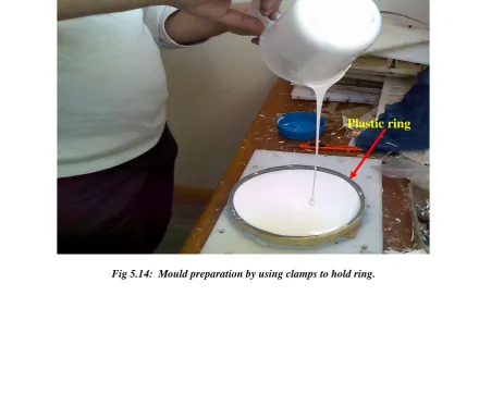
5.1.1 Mould preparation --- 95
5.4.2 Manufacturing grinding wheels: --- 98
5.5 Experimental Methods --- 101
5.4.2 Various grinding and commercial wheel --- 101
Chapter 6 --- 103
Results and Discussion --- 103
6.1 Experimental Results and Discussion --- 103
6.1.1 Wet\Dry cutting experiment --- 103
6.1.2 Dimensional Analysis --- 105
6.1.3 Grinding Wheels experimental comparison --- 111
6.2 Simulation results and discussion --- 129
6.2.1 von-Mises stress --- 133
6.2.2 Principal stresses --- 134
6.2.3 Maximum shear stress --- 135
6.3 Grinding wheel optimisation --- 141
6.4 Comparison between numerical and experimental results --- 143
Chapter 7 --- 147
Conclusions and Recommendations for Further Work --- 147
7.1 Conclusions --- 147
7.2 Recommendations for Further Work --- 151
References --- 152
7
Nomenclature
A Cross sectional area of the unreformed chip;
0
A Interface area of a grain;
A Depth of cut;
c
a Engaged length of a grain;
d
A Dressing area;
d
a Dressing depth;
m
A Mean chip cross sectional area;
p
A Area of the pile-up material;
t
A Real contact area between wheel and workpiece;
B Grinding width, radius of the projected area of grain;
c
b Cutting width of a grain;
C Constant;
C’ Constant of constrain;
o
C Constant;
1
C Static cutting edge density;
c
d Diameter of the equivalent grain constant circle;
e
d Equivalent diameter;
g
d Diameter of abrasive grain;
s
d Wheel diameter;
w
d Workpiece diameter
E Energy consumption;
c
e Specific energy;
cc
e Specific cutting energy;
f
e Specific energy due to friction;
g
e Specific energy for a single grain;
8 0
F Initial grinding;
1
F Constant;
2
F Constant;
c
f Cutting force on grain;
d
F Dressing force;
d
f Dressing lead;
e
F Critical grinding force at the end of the secondary grinding stage
n
F Normal grinding force;
n
f Normal grinding force on a grain;
nc
F Normal grinding cutting force;
nc
f Normal grinding cutting force on a grain;
nf
f Normal grinding friction force on a grain;
n
F Specific normal grinding force
no
F Minimum specific normal grinding force to removal metal;
ns
F Normal grinding force;
G Grinding ratio;
H Hardness of workpiece or wheel hardness grade number;
M Grain size number;
M Probability of grain fracture in a unit grinding cycle;
N The number of revolutions of the workpiece;
d
n The number of dressing passes;
w
n Workpiece rotational speed;
s
n Wheel rotational speed;
P Grinding power;
P’ Specific power;
Po Constant;
ch
P The chip formation component of the grinding power;
pl
9 sl
P The sliding component of the grinding power;
w
Q Grinding removal rate;
R Force of of identification ;
R Radius of the workpiece, exponent constant;
c
R Rockwell hardness;
S Wheel structure number;
T Period of one workpiece revolution;
T Grinding time or cutting depth of a grain;
Tmax Maximum cutting depth of cut of the grains;
X Exponent
Y Component;
Z Component;
Proportion of grains actually cutting or coefficient of
significance
Proportion of the groove volume removed ;
Diamond sharpness ratio;
Average spacing of grains along the co-ordinate axes;
r Workpiece radius error;
ro Initial workpiece roudness error;
Deflection of the grinding system;
c Local workpiece deformation;
d Elastic deflection of a grain in dressing; rt Rotation of the grain;
w Deflection of the grain centre;
Constant;
Constant;
Half-angle of the scratch
Grinding force ratio ft/ fnor Fn /Ft;
)
(t Cutting edge density during grinding;
10 c Cutting edge density at the end of the secondary grinding stage
w Metal removal parameter; w Strength of the grinding wheel;
Time constant;
Tip angle of the dressing diamond;
11
List of Figures
Fig 2.1: Standard Shapes of Grinding Wheel Faces ANSI B74.2-1982 --- 27
Fig 2.2: subdivision of grinding operations Suggested by Armarego & Brown (1969) --- 29
Fig 2.3: Comparison of pendulum and creep feed grinding processes --- 30
Fig 2.4: Changes in cutting force, surface roughness and wheel wear with increasing wheel speed --- 32
Fig 2.5: low workpiece surface temperature and the temperature trend --- 33
Fig 2.6: Illustration of a typical wheel or bonded abrasive marking --- 36
Fig 2.7: Anticipated location of burn in sidewall during creep feed grinding --- 40
Fig 2.8: Theoretical heat flux to surface and sidewall during abrasive cut-off --- 41
Fig 2.9: Sidewall temperature curves for the abrasive cut-off process --- 41
Fig 2.10: Schematic of the cylindrical traverse grinding process --- 42
Fig 2.11: Primary effects of lubrication and cooling in the machining process --- 43
Fig 2.12: The effect of grinding fluid on grinding power --- 45
Fig 2.13: The effect of grinding fluid on grinding --- 45
Fig 2.14: Schematic of thermocouple technique for measurement of surface temperatures during grinding --- 47
Fig 2.15: Schematic of infra-red temperature measurement system for measurement of grinding temperatures --- 48
Fig 2.16: Schematic of infra-red pyrometer with local optical fibre temperature measurement system for measurement of grinding temperatures --- 49
Fig 2.17: Complete temperature distribution shown in metallography of a cutting tool --- 49
Fig 2.18: Sample time temperature transformation lines for analysis of cutting tools with metallography --- 50
12
--- 51
Fig 2.20: Graphical representation of isotherms shown in Figure 2.19 --- 51
Fig 2.21: Vickers hardness test --- 56
Fig 2.22: Thermal analysis by using COSMOS HSTAR --- 58
Fig 2.23: FEA of fluid flow by using Solidworks COSMOS Flo works. --- 59
Fig 3.1: Dressing of grinding wheel by diamond dresser. --- 61
Fig 3.2: Kinematic description of dressing. --- 61
Fig 5.1: Wallpaper strips used to make similar pattern on mould --- 87
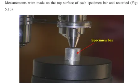
Fig 5.2: Bars used in experiments --- 88
Fig 5.3: Oven used in manufacturing grinding wheel --- 89
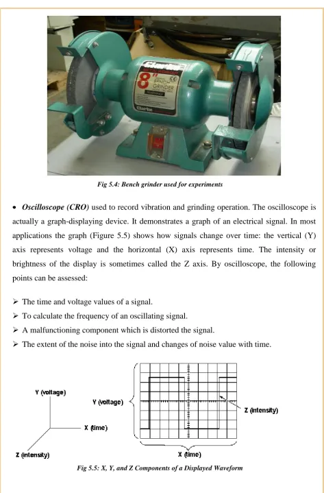
Fig 5.4: Bench grinder used for experiments --- 90
Fig 5.5: X, Y, and Z Components of a Displayed Waveform --- 90
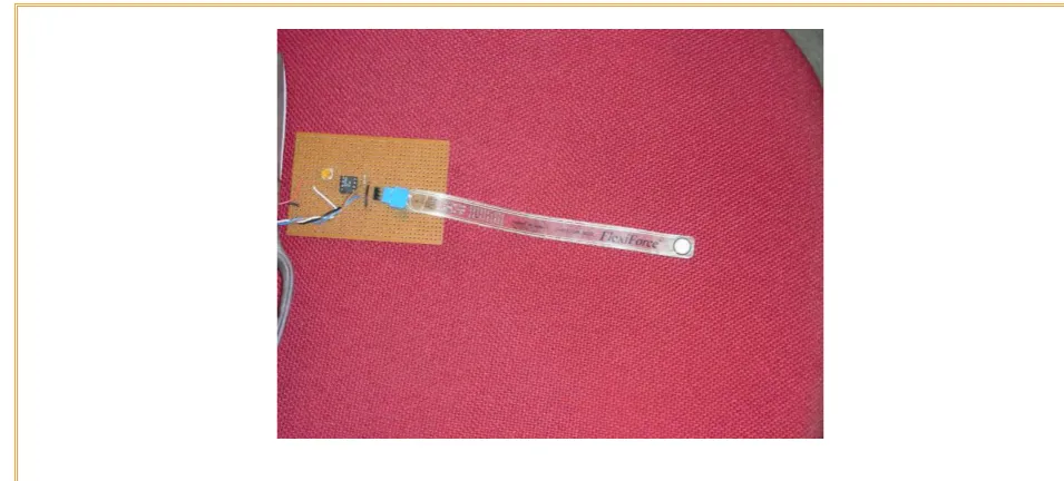
Fig 5.6: Flexiforce pressure sensor --- 91
Fig 5.7: Force range against Voltage --- 91
Fig 5.8: Digital diagram of Flexiforce pressure sensor --- 92
Fig 5.9: Flexiforce pressure sensor --- 93
Fig 5.10: Constructed assembly holding bar without V- block --- 93
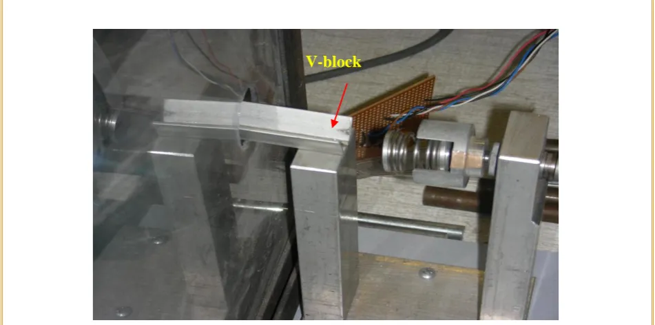
Fig 5.11: Modification of Constructed assembly with V- block.--- 94
Fig 5.12: Microhardness testing machine --- 94
13
Fig 5.14: Mould preparation by using clamps to hold ring. --- 96
Fig 5.15: Another mould Preparation by using catalyst and curing agent --- 97
Fig 5.16: mould used to manufacture grinding wheel--- 97
Fig 5.17: Mixing of silicon carbide with araldite epoxy resin --- 98
Fig 5.18: Filling material in the gap between the mould and aluminium disc --- 99
Fig 5.19: Grinding wheel with parallel grooves lines --- 100
Fig 5.20: Grinding wheel with cross lines --- 100
Fig 5.21: Installing grinding wheel on grinder --- 101
Fig 5.22: Grinding of mild steel bar on commercial wheel --- 102
Fig 6.1: Measured versus predicted unit grinding force (J/sec) --- 109
Fig 6.2: Total materials removed by C --- 113
Fig 6.3: Total consumed voltage during grinding of a variety of workpieces --- 113
Fig 6.4: Aluminium particles stuck on C. --- 114
Fig 6.5: Graph of material removed by wheel made of grain size 0.25 --- 115
Fig 6.6: Graph of voltage taken by grinding wheel made of grain size 0.25 --- 116
Fig 6.7: Total Material removed by W2 --- 117
Fig 6.8: Voltage utilised during grinding of different bars by W2 --- 118
Fig 6.9: Material removed by W3 --- 119
Fig 6.10: Consumed voltage by W3 --- 119
Fig 6.11: Total material removed by grinding W4 --- 120
Fig 6.12: Voltage taken during grinding of wheel made of grain size 0.1 --- 121
Fig 6.13: Graph of total material removed by the wheel with side lines --- 122
Fig 6.14: Graph of voltage taken during grinding of wheel with side lines --- 123
Fig 6.15: Total materials removed by W6 --- 124
Fig 6.16: Recorded voltages during grinding of various bars by W6 --- 125
Fig 6.16: Hardness of work pieces material and voltage taken by all grinding wheels---- 126
Fig 6.17: Recorded voltage vs. material removed from steel bar using C, W5 & W6 --- 128
Fig 6.18: Total removed material vs. Recorded voltage by C, W5 & W6 --- 129
Fig 6.19: Ansys simulation of the commercial grinding wheel --- 130
highlighting the boundary conditions --- 130
Fig 6.20: Ansys simulation of the grinding wheel with groove --- 130
highlighting the boundary conditions --- 130
Fig 6.21: Ansys simulation of the grinding wheel with cross groove --- 131
14 Fig 6.22: FEA profile of aluminium bar with C wheel showing von-Mises stress distribution --- 134
Fig 6.23: FEA profile of steel bar with W5 wheel showing principal stress distribution -- 135
Fig 6.24: FEA profile of brass bar with W6 wheel showing maximum shear stress
distribution --- 136
Fig 6.25: Different stresses(maximum) obtained from FEA profiles of C, W5 & W6 for various bars --- 137
Fig 6.23: Total removed material vs. von-Mises stress and voltage taken by C, W5 & W6 --- 139
Fig A.1 : Ansys simulation of the grinding wheel highlighting the boundary conditions - 161
Fig A.2 : FEA profile of aluminium bar with commercial grinding wheel showing von-Mises Stress --- 162
Fig A.3 : FEA profile of aluminium bar with commercial grinding wheel showing Principal Stress --- 163
Fig A.4 : FEA profile of aluminium bar with commercial grinding wheel showing Shear Stress --- 164
Fig A.5 : FEA profile of steel bar with commercial grinding wheel showing von-Mises Stress --- 165
Fig A.6 : FEA profile of steel bar with commercial grinding wheel showing Principal Stress --- 166
Fig A.7 : FEA profile of steel bar with commercial grinding wheel showing Shear Stress 167
Fig A.8 : FEA profile of brass bar with commercial grinding wheel showing von-Mises Stress --- 168
Fig A.9 : FEA profile of brass bar with commercial grinding wheel showing Principal Stress --- 169
Fig A.10 : FEA profile of brass bar with commercial grinding wheel showing Shear Stress --- 170
Fig A.11 : FEA profile of brass bar with commercial grinding wheel showing Shear Stress --- 171
Fig A.12 : Ansys simulation of the grinding wheel with groove highlighting the boundary conditions --- 172
Fig A.13 : FEA profile of aluminium bar with groove grinding wheel showing von-Mises Stress --- 173
Fig A.14 : FEA profile of aluminium bar with groove grinding wheel showing Principal Stress --- 174
Fig A.15 : FEA profile of aluminium bar with groove grinding wheel showing Shear Stress --- 175
15 Fig A.17 : FEA profile of aluminium bar with groove grinding wheel showing Principal Stress --- 177
Fig A.18 : FEA profile of aluminium bar with groove grinding wheel showing Shear Stress --- 178
Fig A.19 : FEA profile of brass bar with groove grinding wheel showing von-Mises Stress --- 179
Fig A.20 : FEA profile of brass bar with groove grinding wheel showing Principal Stress --- 180
Fig A.21 : FEA profile of brass bar with groove grinding wheel showing Shear Stress -- 181
Fig A.22 : FEA profile of brass bar with groove grinding wheel showing von-Mises Stress --- 182
Fig A.23 : FEA profile of brass bar with groove grinding wheel showing von-Mises Stress --- 183
Fig A.24 : Ansys simulation of the grinding wheel with cross groove highlighting the boundary conditions --- 184
Fig A.25 : FEA profile of aluminium bar with cross groove grinding wheel showing von-Mises Stress --- 185
Fig A.26 : FEA profile of aluminium bar with cross groove grinding wheel showing von-Principal Stress --- 186
Fig A.27 : FEA profile of aluminium bar with cross groove grinding wheel showing von-Mises Stress --- 187
Fig A.28 : FEA profile of steel bar with cross groove grinding wheel showing von-Mises Stress --- 188
Fig A.29 : FEA profile of steel bar with cross groove grinding wheel showing Principal Stress --- 189
Fig A.30 : FEA profile of steel bar with cross groove grinding wheel showing Shear Stress --- 190
Fig A.31 : FEA profile of steel bar with cross groove grinding wheel showing von-Mises Stress --- 191
Fig A.32 : FEA profile of brass bar with cross groove grinding wheel showing von-Mises Stress --- 192
Fig A.33 : FEA profile of brass bar with cross groove grinding wheel showing Principalm Stress --- 193
Fig A.34 : FEA profile of brass bar with cross groove grinding wheel showing Shear Stress --- 194
Fig A.35 : FEA profile of brass bar with cross groove grinding wheel showing von-Mises Stress --- 195
16
List of Tables
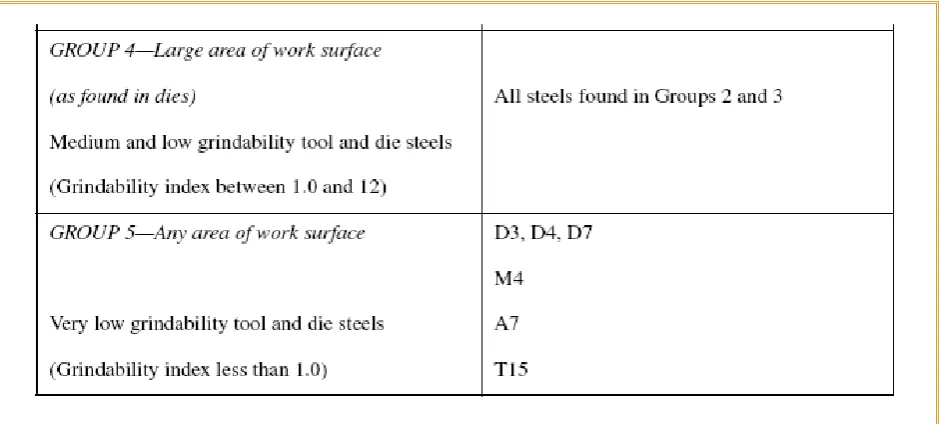
Table 2.1: Classification of Tool Steels by their Relative Grindability --- 24
Table 2.2: Recommendations for improvements to get good and effective results --- 25
Table 2.3: Effect of grinding conditions on wheel hardness behaviour --- 37
Table 5.1: Properties of silicon carbide measured at room temperature --- 86
Table 5.2: Physical data of dibutyltin dilaurate --- 86
Table 5.3: Safety (MSDS) data sheet Table for dibutyltin dilaurate --- 87
Table 5.4: Bars Size & Hardness --- 88
Table 5.5: Physical Properties of Flexiforce --- 92
Table 5.6: Typical Performance of Flexiforce --- 92
Table 6.1: Taly surf measurement of work piece material mild steel during wet cutting experiment --- 104
Table 6.2: Talysurh measurement of workpiece material MILD STEEL during wet cutting experiment --- 104
Table 6.3: Talysurf measurement of workpiece material –Mild steel during dry cutting experiment --- 104
Table 6.4: Talysurf measurements of Mild steel workpiece during dry cutting experiment --- 104
Table 6.5: Different variables together with M, L & T --- 106
Table 6.6: Coding and levels of Factors --- 108
Table 6.7: Cross- sectional area of different bars --- 112
Table 6.8: Experimental Data of commercial grinding wheel (C) --- 112
Table 6.9: Voltage consumed and total materials removed by W1 --- 115
Table 6.10: Voltage taken and total material removed by W2 --- 116
Table 6.11: Voltage used and total materials removed by W3 --- 118
Table 6.12: Voltage taken and total materials removed by W4 --- 120
Table 6.13: Voltage taken and total material removed by W5 --- 122
Table 6.14: Recorded voltages and total material removed by W6 --- 123
Table 6.15: Work pieces hardness & voltage taken by all grinding wheels --- 125
Table 6.16: Total material removed by all wheels to grind Mild steel, Brass and Aluminium bars --- 126
Table 6.17: Different Stresses data collected from FEA simulation --- 132
17
Chapter 1
Introduction
1.1
Background
Grinding wheels are made of natural or synthetic abrasive minerals bonded together in a matrix to form a wheel. While such tools may be familiar to those with home workshops, the general public may not be aware of them because most have been developed and used by the manufacturing industry. In this sector, grinding wheels have been important for more than 150 years.
For manufacturers, grinding wheels provide an efficient way to shape and finish metals and other materials. Abrasives are often the only way to create parts with precision dimensions and high-quality surface finishes. Today, grinding wheels appear in nearly every manufacturing company in the United States, where they are used to cut steel and masonry block; to sharpen knives, drill bits, and many other tools; or to clean and prepare surfaces for painting or plating. More specifically, the precision of automobile camshafts and jet engine rotors rests upon the use of grinding wheels. Quality bearings could not be produced without them, and new materials such as ceramic or material composites would be impossible without grinding wheels to shape and finish parts.
Sandstone, an organic abrasive made of quartz grains held together in natural cement, was probably the earliest abrasive; it was used to smooth and sharpen the flint on axes. By the early nineteenth century, emery (a natural mineral containing iron and corundum) was used to cut and shape metals. However, emery's variable quality and problems with importing it from India prior to its discovery in the United States prompted efforts to find a more reliable abrasive mineral.
18 developed an abrasive material more reliable than both natural minerals and silicon carbide. Research into synthetic minerals also led to production of the so-called super abrasives. Foremost in this category are synthetic diamonds and a mineral known as cubic boron nitride (CBN), second in hardness only to the synthetic diamond. Today, development continues, and a seeded-gel aluminium oxide has just been introduced.
Throughout the grinding wheel's history, the bond that holds the abrasive grains together has proven as important as the grains themselves. The success of grinding wheels began in the early 1840s, when bonds containing rubber or clay were introduced, and by the 1870s a bond with a vitrified or glass-like structure was patented. Since then, bonds used in grinding wheels have been continually refined.
In the grinding operation, the kinematics relationship within the motion(s) of the workpiece and the grinding wheel depends on its cutting grain, the grain size and the distance between two adjacent grains, that is the cutting path-length, which collectively dictates the chip thickness. Also, when the workpiece material can no longer withstand the tearing stress, a chip is formed.
Hence the shape of an idealized chip may be deemed to have been determined by the wheel speed, the removal rate and the distribution of the cutting edges on the wheel surface. Alternatively, the wheel speed and the removal rate may be estimated and/or expressed by the equivalent chip thickness. Equally, the consumption of energy is also influenced by the chip size. In summary, the topography of the inside of a grinding wheel surface and granular particles may be considered to play an important role in the process of grinding.
To select an optimum grinding wheel, a number of factors must be considered. Including the following parameters:
Type of the materials to be ground
Kind of abrasive particles used in the wheel The amount of stock to be removed
19 For selection of a grinding wheel that allows the abrasive in the wheel to cut efficiently, the wheel must contain the proper bond that is, the material that holds abrasive grains together so that they can cut effectively.
In this project a novel grinding wheel will be made by choosing and mixing appropriate abrasive powder, with a known size distribution of particles, as well as bonding material. This process will be followed by curing process, using an oven. The bonding materials may be mixed with other materials that may be leached out by liquid/solid extraction thus forming a porous novel wheel for study here.
1.2
Brief description of the project
In this study a grinding wheel was selected and fixed on to the machine, Jones Shipman model 540, which will operate at its fixed speed. This rotating grinding wheel will be used to wear off a pre set depth from the top of a work piece. The nature of grinding wheel will be selected to suit the material of construction of the work piece. For each work piece the power consumed during grinding was recorded and analysed versus the surface properties of the grinding wheel that include blinding of the interstices between grinding particles. In this experimental work, effects of lubrication and cooling have been also assessed in order to examine their influence on surface finish.
1.2.1
Grinding Wheels
Conventional grinding wheels are made from mixing measured constituents of a selected abrasive powder followed by other steps. The chosen constituents are placed in a mould and pressed into a wheel shape. The wheel is then fixed in a conventional or electric oven. Aluminium oxide, silicon carbide, bubble alumina, cubic boron nitride are some of the conventional abrasive types particle which commonly have been used in grinding.
20 aluminium oxide and silicon carbide are very hard, but silicon carbide is harder, more brittle and more expensive than aluminium oxide abrasive.
Aluminium oxide is used for grinding steels and steel alloys. Silicon carbide abrasive is used for grinding cost-iron, non-ferrous metals, non-metallic materials. The working of hard and/or brittle materials generally requires a wheel with a fine hard grit size mixed with softer grains. Hard materials resist the penetration of abrasive grains and cause them to dull quickly. The combination of finer grit and softer grade lets abrasive grains brake away as they become dull, exposing fresh, sharp cutting points. Wheels with coarse grit and hard should be chosen for materials that are soft ductile and easily penetrated.
1.3
Summary of Research Contributions
This research program adopts a completely new and innovative investigative approach to the process of optimizing the performance of a grinding wheel during continuous use in any manufacturing operation. The main points of innovative study are as follows.
The arrangement of abrasive particles, hardness and material of construction, size distribution and final porous structure of a selected number of commercially available grinding wheels will be noted under high magnification. The bridging i.e. clogging action of the pores of the grinding wheel by separated particles of the metal surface being removed during grinding will be studied as a function of the above properties. The experimental results will be compared against a numerical FEA model as well as a mathematical model of the grinding process.
21
1.4
Objectives of the investigation
To study the overall sharpness of the grinding wheel in terms of its internal granular particles and their effect on the surface finish for both soft and hard metals at different conditions of use. To study the properties of materials of construction including hardness of the granular particles and their size and distributions that affects the grinding wheel efficiency in abrading of soft and hard metal surfaces. To study the mechanism, in order to improve grinding performance, of clogging the cutting surface of the grinding wheel as a function of for example, the surface properties of granular particles and the chips formed during the grinding operation.
1.5
The methodology to be followed in this study
To achieve a successful outcome of this project and meet the criteria for optimum development of the grinding wheel the following methodology have been pursued:
To select appropriate grinding wheels, maximum six, that furnish a defined set of properties e.g. the average size of grains, their hardness, materials of construction and bonding.
To characterise the structure, orientation and size distribution of the particles and pore within a grinding wheel, which are subject of this investigation.
To develop a mathematical model of the grinding process.
To develop a three dimensional finite element model of the grinding wheel
22 This model will help to design a novel grinding wheel being constructed from known particles of selected size distribution and chosen materials of construction. These particles will be impregnated and bonded together using an epoxy polymer followed by a curing process in an oven. This approach will be used to produce two novel grinding wheels. One novel grinding wheel will incorporate a single groove profile for removing the chips formed during grinding and retained between edges of the grinding particles and a second grinding wheel will include crossed groove profile. The iteration will be repeated until the predictions of the model closely matches experimentally obtained data.
Thus the mathematical model may need to be modified which includes the process and forces responsible for retaining the chip in the grinding wheel.
23
Chapter 2
Literature Review
Manufacturing industry has experienced significant changes in recent years as increasing material and labour costs have taken a necessary toll on its competitiveness. Thus a drive exists for significant reductions in product touch and process time. An effective response to these constraints in the metal cutting field can be to reduce processing times with the use of advanced machining technologies.
By grinding wheel can produce surfaces to very close dimensions and a high degree of smoothness. Hard abrasives can cut hard materials. Often grinding is the only way in which some materials, such as tungsten carbides, may be accurately shaped to final size. Many combinations of abrasive crystals and bonding materials may be used to obtain various rates of cutting and different kinds of surfaces on many type of materials.
2.1
Selection of a grinding wheel
24 The following tabulation indicates the general directions in which the characteristics of the initially selected grinding wheel may have to be altered in order to approach optimum performance. Variations in a sense opposite to those shown will call for wheel characteristic changes in reverse.
25 After having defined the grindability group of the tool steel, the proper operation can be find in the first column of Table 2.2. The second column in this Table distinguishes between different grinding wheel size ranges, since wheel size is an important factor in determining the contact area between wheel and workpiece.
Table 2.2: Recommendations for improvements to get good and effective results
26 To select the best grinding wheel a number of factors must be considered. The first consideration is the material to be ground. The kind of material needs to be ground determines the type of abrasive, which is needed. For example, for grinding steels and the steel alloys, aluminium oxide grinding wheel should be used. For grinding cast iron, non-ferrous metals and non-metallic materials a silicon carbide abrasive must be selected.
A wheel with a fine grit size and a softer grade is required for grinding a hard, brittle material. Hard materials resist the penetration of abrasive grains and cause them to dull quickly. The combination of finer grit and softer grade lets abrasives grains break away as they become dull, exposing fresh, sharp cutting points.
27 Fig 2.1: Standard Shapes of Grinding Wheel Faces ANSI B74.2-1982
28 Several emergent technologies exist in this field, based around the principle of single set-up, high performance machining; examples of which would include Viper Grinding, Prismatic Machining and High Efficiency Deep Grinding (HEDG).
The literature review will consider the fundamentals of the HEDG process and its predecessors, creep and high speed grinding, as a precursor to the HEDG technology. Following this, temperature measurement techniques employed in both grinding and where relevant alternative metal cutting processes will be considered as a precursor to understanding the development of a temperature measurement methodology for an aggressive environment. Finally the review will consider models of burn threshold applied to the process in terms of the development of the residual stress profile and its prediction via thermal modelling techniques.
2.2
The Grinding Process
According to the U.S. Census Bureau (2006), 2005 saw the shipment of some 792 external cylindrical grinding machines and 564 surface grinding machines with individual values of over $3,025 and a total combined value of over $80 million. Grinding is a major aspect of the production industry, meeting the expectations of Merchant (1971) in terms of both the requirement for grinding processes and the technological advancements attained.
Broadly described by Armarego & Brown (1964), grinding is one of a number of abrasive processes including honing, lapping and super finishing. They have described the abrasive process as a metal cutting process involving hard, sharp and friable abrasive grains, which as a result of their ability to produce a fine surface finish are often considered as finishing processes.
29 Armarego & Brown (1964) discuss grinding in its role as the most common and best known of the abrasive processes, abrasives are bonded to a wheel or cup, which is power driven. The process consists of a random dispersion of grains in the wheel, taking very small but frequent cuts and producing very small chips. They have divided grinding operations into three major types as shown in Figure 2.2.
Fig 2.2: subdivision of grinding operations Suggested by Armarego & Brown (1969)
This should be considered in addition to the specialised regimes described in the following pages, which include creep feed, high speed and high efficiency deep grinding primarily utilised in the broad cylindrical and surface grinding operations.
2.2.1
Creep Feed Grinding
Creep feed grinding exhibits a number of benefits over traditional grinding processes. Slow rates of feed with large depths of cut and high levels of coolant application promote a low temperature at the contact and a high quality finished surface.
30 Fig 2.3: Comparison of pendulum and creep feed grinding processes
Shaw (1996) describes the creep feed grinding process in comparison to the conventional pendulum grinding process and presents the schematic comparison of Figure 2.3. He commented on the processes ability to remove the required material in a single pass, when compared to the multiple passes of pendulum grinding and highlights its use in the production of deep slots in hydraulic pumps and fir tree patterns in turbine blade roots.
Shaw (1996) continues to state that the most important aspect of a successful creep feed grinding process is the application of coolant. Coolant must be applied such as to provide uniform coverage of the wheel -work contact zone in order to reduce the high contact zone temperatures generated. The wheel is required to have an open structure such that pockets of fluid can be carried into the contact zone, whilst the use of an air scraper to prevent the boundary layer of air around the wheel deflecting the coolant is advised.
Describing the process, Werner (1979) distinguishes creep feed grinding from conventional grinding regimes by four characteristic features. The total grinding force and wheel-work contact zone temperatures are increased, whilst the individual grit force and work surface temperature are decreased. The increase in total grinding force is described as the result of the increased depth of cut, this increase results in a contact length which increases by a factor of 30 to 100 times. This results in an increased number of grits in the contact zone and hence a decrease in the individual grit force.
31 feed process can be used to dramatically increase productivity when large amounts of stock have to be removed and the surface requirements are high. It should be noted that in some instances creep feed grinding does not create a greater energy requirement and the slow movement of the heat source can also result in elevated temperatures if uncontrolled.
2.2.2
Wheel speed
Wheel speed in operation is another factor that affects the choice of wheel bond. Usually vitrified wheels are used at speeds less than 6,500 surface revolution per minute. The vitrified bond may break at higher speed. Using wheels with coarser grit and softer grade, for a broad area of contact between the wheel and the work piece, will ensure a free, cool cutting action under the heavier load imposed by the size of the surface to be ground. Smallest areas of grinding contact require wheels with finer grits and harder grades to withstand the greater unit pressure.
2.2.3
High Speed Grinding
For the purposes of this thesis, high speed grinding refers to those grinding processes in which a wheel speed of 60 m/s is exceeded. Increasing the speed of the grinding wheel for a given grinding process produces a number of desirable effects. Knig et al. (1971) presents an early overview of work in the field compiling results from several authors and presenting evidence (Figure 2.4) of the decreasing cutting force, surface roughness and wheel wear as a result of increasing wheel speeds.
High wheel speeds in modern grinding applications are largely the result of improvements in grinding wheel technology. Wheel requirements for successful high speed grinding are described by Jackson et al. (2001).
32 The most suitable abrasive for high speed grinding applications is cubic boron nitride (CBN), Tawakoli (1993) for example highlights the use of electroplated CBN steel wheels, allowing wheel speeds to exceed 200m/s. Jackson et al. (2001) also comment on the suitability of CBN considering its high hardness and thermal and chemical stability to result in an ideal product for high speed ferrous machining. They have continued to describe the application of electroplating as the preferred bonding system with steel wheels and consider cutting speeds in excess of 280 m/s to be possible.
Fig 2.4: Changes in cutting force, surface roughness and wheel wear with increasing wheel speed
2.2.4
High Efficiency Deep Grinding
The High Efficiency Deep Grinding (HEDG) regime is the result of the development of wheel and machine technologies capable of delivering both high wheel and workpiece feed rates with a large depth of cut. The process is the product of the high speed and creep feed grinding regimes utilising the benefits of high wheel speeds at large depths of cut and feed rates to achieve high stock removal rates.
33 The beneficial contact conditions, high angle of inclination and high wheel and workpiece speeds result in a low workpiece surface temperature and the temperature trend presented in Figure 2.5. It is to be questioned whether the same profile would exist in the sidewall, where no benefit from an angle of inclination is to be found.
Correct selection of the grinding is important for the achievement of stable grinding behaviour and long wheel life. In particular, an appropriate rate of self-sharpening is usually considered to be desirable (King & Hahn, 1986). The total grinding process includes dressing as well grinding.
Fig 2.5: low workpiece surface temperature and the temperature trend
Most grinding research is focused on the grinding process rather than the dressing process. Because of the random nature of the grinding wheel topography, the relationships between dressing and grinding parameters are difficult to analyse deterministically. It can be argued that dressing is the least understood but one of the most influential aspects of the grinding process.
34 The wheel specification in the standard marking system is defined by the following characteristics (UGWC 1992):
Type of abrasive: The particular abrasive used in a wheel is chosen based on the way it will interact with the work material. The ideal abrasive has the ability to stay sharp with minimal point dulling. When dulling begins, the abrasive fractures, creating new cutting points. Mechanism of each abrasive type is unique with distinct properties for hardness, strength, fracture toughness and resistance to impact.
The type of material to be ground affects the selection of abrasive, grain size and grade. Alumina abrasives (UGWC 1992) are used for grinding high tensile materials such as steel and ferrite cast irons. Silicon carbide abrasives that are even more friable are used for grinding low tensile strength materials and non-metallic materials. CBN abrasive wheels (King & Hahn, 1986) are suitable for grinding high speed steel and high alloy steels. Carbide, ceramic, glass and plastic are often ground using diamond wheels. The harder the workpiece, the harder the grain required. For particular grain hardness, a hard workpiece requires a ‗softer‘ bond than a soft workpiece (UGWC 1992).
- Aluminium oxide is the most common abrasive used in grinding wheels
(Yamaguchi et al., 1999). There are many different types of aluminium oxide abrasives, each specially made and blended for particular types of grinding jobs. Each abrasive type carries its own designation-usually a combination of a letter and a number. These designations do vary from one manufacturer to another. Aluminium oxide are chosen for grinding carbon steel, alloy steel, high speed steel, annealed malleable iron, wrought iron, and bronzes and similar metals. Aluminium oxide crystals are used principally in grinding ferrous and other materials that have a high tensile strength because they are tough and resist fracture to a high degree.
- Silicon carbide is harder than aluminium oxide, but its crystals are not as tough and break easily. Silicon carbide crystals fracture easily and it is especially adapted to cutting materials with low tensile strength such as brass, aluminium, copper, cast iron, rubber, and plastics. It is also used in grinding hard, brittle materials such as carbide, stone and ceramics.
- Ceramic aluminium is the newest major development in abrasives. This is a
35 thousands of new cutting points. This abrasive is exceptionally hard and strong. It is primarily used for precision grinding in demanding applications on steels and alloys that are most difficult to grind. The abrasive is normally blended in various percentages with other abrasives to optimize its performance for different applications and materials.
- Zirconia alumina is abrasive made from different percentages of aluminium
oxide and zirconium oxide. The combination results in tough durable abrasive that works well in rough grinding applications, such as cut-off operations, on a broad range of steels and steel alloys. As with aluminium oxide, there are several different types of zirconia alumina from which to choose.
Abrasive grain size: The rate of stock removal and surface texture required affect the choice of abrasive size and bond type. High stock removal rate usually require coarse grain wheels. Fine surface texture and small tolerances need a finer grain size. Extremely fine surface texture usually requires resinoid, rubber or shellac-bonded wheels (UGWC 1992). Selection of the size of grain will depend on the amount of material to be removed, the finish desired and the mechanical properties of the material to be ground, the larger the grains, faster the material will be removed. Coarse grains are better adapted to grinding soft, ductile materials while fine grains are best when fine finishes and close accuracy is required. Selection of size of grain will depend on the amount of material to be removed, the finish desired and the mechanical properties of the material to be ground, the larger the grains, the faster material will be removed. Coarse grains are better adapted to grinding soft, ductile materials while fine grains are best when fine finishes and close accuracy are required.
Grade of the wheel: The letters designating grade indicate the relative strength of the bond that holds the abrasive in place. With given type of bond it is the amount of bond that determines the hardness (grade). When the amount of bond is increased, the size of the bond posts connecting each abrasive grain to its neighbours is increased. A wheel is said to have a soft grade if only a small force is needed to release the grains. It is relative amount of bond in the wheel that determines its grade or hardness.
36 are demonstrated in Figure 2.6, which shows the makeup of a typical wheel or bonded abrasive marking.
Fig 2.6: Illustration of a typical wheel or bonded abrasive marking
The meaning of each letter and number in this or other markings is indicated by the following complete list.
1) Abrasive Letters: The letter (A) is used for aluminium oxide, (C) for silicon carbide, and (Z) for aluminium zirconium. The manufacturer may designate some particular type in any one of these broad classes, by using exclusive symbol as a prefix.
2) Grain Size: The grain sizes commonly used and varying from coarse to very fine are indicated by the following numbers: 8, 10, 12, 14, 16, 20, 24, 30, 36, 46, 54, 60, 70, 80, 90, 100, 120, 150, 180, and 220. The following additional sizes are used occasionally: 240, 280, 320, 400, 500, and 600. The wheel manufacturer may add to the regular grain number an additional symbol to indicate a special grain combination.
3) Grade: Grades are indicated by letters of the alphabet from A to Z in all bonds or processes. Wheel grades from A to Z range from soft to hard.
4) Structure: The use of a structure symbol is optional. The structure is indicated by Nos. 1 to 16 (or higher, if necessary) with progressively higher numbers indicating a progressively wider grain spacing (more open structure).
5) Bond or Process: Bonds are indicated by the following letters: V- Vitrified, S-Silicate, E- Shellac or Elastic, R- Rubber, RF- Rubber reinforced, B- Resinoid (synthetic resins), BF- Resinoid reinforced, O- oxychloride.
37 If the cutting edges on the grinding wheel tend to glaze and are therefore less likely to be resharpened by fracture, the grinding wheel is described as acting ‗hard‘. When the wear of cutting edges on the grinding wheel is mostly due to the fracture of the grains or bonds, the wheel is described as acting ‗soft‘.
The effects of the grinding condition on wheel behaviour are summarized in Table 2.3 (UGWC 1992).
Table 2.3: Effect of grinding conditions on wheel hardness behaviour
grinding conditions behaviour of wheel
High wheel speed hard
High work speed soft
High in feed rate soft
Grain structure:
The grinding contact area also affects the selection of the wheel grade and structure. A large contact area requires a wheel of soft grade and open structure. Vitrified wheels for dry grinding need to be one or two grades softer than for wet grinding (UGWC 1992). The grain structure number indicates the relative spacing of the abrasive grains.
When the grains are close together relative to the grain size, the wheels have low structure numbers such as 1,2,3,4 & 5. Wider spacing relative to grain size is designating by higher numbers. Selection of the proper structure, or spacing between the grains, is governed by the finish required, the nature of the operation, and the mechanical properties of the material to be ground.
38 grade or coarser grain size is required. When the surface texture and dimensional accuracy of workpiece have deteriorated, the wheel needs to be redressed. If this happens too frequently, the wheel is said to be soft or too coarse, the wheel is said to be too soft or too coarse and either a harder grade wheel or a finer grain size is required.
Type of bond:
Bond is the medium that holds the grains together in the form of a wheel, or on belt or disk. The bond functions in the same way as tool post and holds the grains or cutting tools in position until they become dull and are torn out and fresh grains exposed. Vitrified bonds, organic substances and rubber are three principal types of bonds used in conventional grinding wheels. Each type is capable of giving distinct characteristics to the grinding action of the wheel. The type of bond selected depends on such factors as the wheel operating speed, the type of grinding operation, the precision required and the material to be ground.
- Vitrified bonds
Most grinding wheels are made with vitrified bonds, which consist of mixture of carefully selected clays. At the high temperatures produced in kilns where grinding wheels are made, the clays and the abrasive grain fuse into a molten glass condition. During cooling, the glass forms a span that attaches each grain to its neighbour and supports the grains while they grind.
Grinding wheels made with vitrified are very rigid, strong, and porous. They remove stock material at high rates and grind to precise requirements. They are very hard, but at the same time they are brittle like glass. The pressure of grinding breaks down vitrified bonds.
- Organic substances
39 higher speeds, and they are often used for wheels in fabrication shops, foundries billet shops and for saw sharpening and gumming.
- Rubber
Another type of organic bond is rubber and wheels made with rubber bonds offer smooth grinding action. Rubber bonds are often found in wheels used where a high quality of finish is required, such as ball bearing and roller bearing races. They are also frequently used for cut-off wheels where burr and burn must be held to a minimum.
2.2.5
Vertical Side Face Grinding
One of the most common applications for high performance grinding applications such as creep feed and high efficiency deep grinding is the production of deep slots and profiles. The production of a deep feature using the grinding process results in the development of a vertical sidewall. This sidewall can experience a differing wear and thermal profile to the axis parallel surface.
Both Mindek & Howes (1996) consider the effects of the presence of a sidewall during the grinding process. They discuss the effect of the sidewall in creep feed grinding, they highlight the limitation of coolant access into the sidewall and the wear on the wheel edge radius as detrimental to the heat flux into the sidewall and the holding of tolerance in the bottom of the slot. The heat flux into the sidewall is considered to increase as the wheel begins to gather debris and worn wheel grits are not removed from the wheel.
40 Fig 2.7: Anticipated location of burn in sidewall during creep feed grinding
The application of deep grinding of narrow slots in the HEDG regime is discussed by Werner & Tawakoli (1988b) and considers the application of an optimised wheel geometry for slot grinding. The authors developed a solid wheel, with partial electroplating of the CBN abrasive to the wheel flank or sidewall. This was shown to be the result of experimentation with a fully electroplated wheel and a slotted wheel and permits an improved flow of coolant into the sidewall and reduces sidewall friction. In addition to the benefits of the wheel geometry, a cleaning nozzle arrangement was added to the set-up to remove loaded metal particles from the wheel surface. The use of the optimised wheel geometry is shown to successfully produce slots of 25mm depth by 1.5mm wide in testing.
41 Fig 2.8: Theoretical heat flux to surface and sidewall during abrasive cut-off
Fig 2.9: Sidewall temperature curves for the abrasive cut-off process
42
2.2.6
Cylindrical Traverse Grinding
Cylindrical traverse grinding is described by Malkin (1989) as grinding with the addition of a crossfeed motion of the workpiece relative to the grinding wheel in a direction perpendicular to the plane of wheel rotation. The author demonstrates the process schematically (Figure 2.10) highlighting the issue of step wear in the wheel as progressive wear is encountered across the wheel width. This may result in a form error, which is cited as a primary reason for the preference of cylindrical plunge grinding in the production environment. The presence of step wear should be limited however by the application of advanced wheel technologies such as electroplated steel CBN wheels, which should exhibit negligible surface wear.
Fig 2.10: Schematic of the cylindrical traverse grinding process
43 effective width of cut providing an optimised solution for cylindrical traverse grinding.
In keeping with results for surface grinding with high wheel speeds, both surface roughness and grinding forces are reduced in cylindrical traverse grinding. The work of Nakayama et al. (2004) is limited to a maximum depth of cut of 0.3mm, this delivers a specific material removal rate of 2600mm3/mm·s and is within the range of high efficiency deep grinding. The work leaves scope for the investigation of larger depths of cut in keeping with stock removal techniques and does not consider temperatures in the surface or sidewall.
Further work in the field of cylindrical traverse grinding has been demonstrated by Weck et al. (2001), Capello and Semeraro (2002) and Bianchi et al. (2003). These reviews consider the application of the cylindrical traverse grinding process to the finish grinding process and do not consider stock removal applications. Stephenson et al. (2002) did however successfully demonstrate the application of the process in the HEDG regime. They considered the use of high rotational speeds with low cross feeds, suggesting that this resulted in a face grinding mode with grinding primarily occurring at the shoulder face of the grinding wheel.
2.2.7
The Application of Grinding Fluid
In grinding, grinding fluids perform a number of functions within the process. Figure 2.14, presented by Brinksmeier et al. (1999) demonstrates the primary effects of lubrication and cooling in the machining process, further to this however it is commonly accepted that coolant also assists in the removal of grinding chips from both the grinding wheel and grinding zone.
44 Ye & Pearce (1983) consider the effect of the type of coolant in the creep feed grinding of a Nickel-base alloy. They demonstrate through experimentation the benefit on surface roughness and profile retention with the use of oil as a cutting fluid. However it is suggested that in this process the use of oil is more likely to result in workpiece burn and therefore if this is a primary consideration, water based coolants are preferred. Further, it is commented that neat oil permitted a greater production rate; this is relevant to the HEDG process as the high production rates possible with the process could be facilitated by the coolant selection.
For the application of grinding fluid to be successful, the coolant must be able to reach the required area of the grinding zone where its functionality is most required. Both Brinksmeier et al. (1999) and Ebbrell et al. (2000) consider the application of coolant into the grinding zone. Of particular importance to the HEDG regime is the boundary layer of air, which occurs around the wheel periphery as a result of high wheel speeds.
Discussed by Ebbrell et al. (2000), conventional methods of fluid delivery are thought to fail to penetrate the boundary layer, resulting in insufficient cooling in the grinding zone. The authors suggest the use of a jet nozzle to avoid this problem, however the application of coolant tangential to the wheel surface is suggested to result in deflection by the boundary layer and thus an angular application of coolant is required, further benefits may also be achieved with the use of a scraper plate to spoil the air flow and minimise the effect of the boundary layer. Further to work relating to coolant selection, Carmona Diaz (2002) presented an optimised geometry for nozzle positioning in the HEDG regime using the Edgetek SAM at Cranfield University.
45 lubricate the process.
Carmona Diaz (2002) studied the influence of grinding fluids on HEDG with a 51CrV4 low alloy steel. His research concluded that the most appropriate selection of grinding fluid for the HEDG regime was neat or synthetic oil. This supports the work of Ye & Pearce (1983), who, working in the creep feed regime, intimated the suitability of neat oil for high stock removal rate processes. It is accepted that this would be true for cylindrical grinding also, as the benefit appears to be the result of the favourable lubrication qualities of oil.
Fig 2.12: The effect of grinding fluid on grinding power
46
2.2.8
Temperature Measurement
The measurement of temperature in any manufacturing process is complicated by issues of accessibility to and the dynamics of the process in question. When considering machining processes, the accurate measurement of temperature is further frustrated by the addition of lubrication to and the removal of swarf from the cutting zone. This is of particular concern for the grinding process, which in many cases floods the wheel workpiece interface with coolant as in the creep feed grinding process or produces high volumes of waste material as found in stock removal processes.
Reviewed by Komanduri and Hou (2001), a variety of temperature measurement techniques are presently available to the researcher. The authors consider the application of thermocouples, infra-red photography and optical pyrometery, thermal paints, materials of known melting temperature and microstructural change. They conclude that the application of a given temperature measurement technique is dependent on the situation considered. Issues include accessibility, heat source size, dynamics of the process, required accuracy, cost implications, sensor technology and data collection.
The use of thermocouples for temperature measurement in grinding is commonplace. Several examples are available of literature presenting results developed from the process, for example temperature measurements in Rowe (2001) utilised this method for verification of thermal models of HEDG. Tawakoli (1993) presents an example of the use of thermocouples for the development of surface temperatures in grinding regimes. He describes advantages including accuracy, a wide temperature range and the ability to place them in or just below the contact zone via drilled holes. It is also noted that the thermocouples require a reference temperature for set-up.
47 Fig 2.14: Schematic of thermocouple technique for measurement of surface temperatures during grinding
Komanduri & Hou (2001) describe the embedded thermocouple technique process as requiring elaborate preparation, given the requirement for accurate drilling of holes in the surface of an often difficult to machine material. Further, they comment on the disturbance of the heat flow when placed close to the contact surface. They consider that the principal benefits of the system are the ease with which thermocouples can be used and the relatively low cost of the sensors. Kato & Fujii (1997) agree that the termal distortion around the embedded thermocouple may be an issue for the measurement of temperatures at the contact surface in grinding.
Hwang et al. (2003) present an example of the application of an infra-red imaging system to the measurement of temperatures in the grinding process. Trials were performed without the application of coolant by focusing the system onto the sidewall of the grinding sample (Figure 2.15). The authors suggest significant benefits are offered
48 Fig 2.15: Schematic of infra-red temperature measurement system for measurement of grinding temperatures
Earlier measurements of grinding temperature with the use of an infrared radiation pyrometer are presented. An optical fibre is positioned such as to record temperatures at the workpiece surface (Figure 2.16), transferring the data to a remotely located infra-red pyrometer. An experimental set-up utilising a thermocouple for temperature measurement verification was also applied. The chief benefits of the approach are described as the response time and the ability to accurately determine peak temperatures.
Response times of the pyrometer are sufficient to respond to the rapid changes in temperature experienced and thus pick up peak temperatures as well as the average background temperature. More recent work by Müller & Renz (2003) considers the application of an infra-red pyrometer with an optical fibre to a conventional turning process. They agree that the speed of response and the accuracy of the technique are of significant benefit. They describe a metallographic method for determining the temperature gradient in a high speed steel cutting tool. The authors claim that the use of thermocouples and infra-red pyrometry can only provide an indication of the character of the temperature distribution in the tool and that this is inadequate.
49 changes in the material, the temperature gradient can be determined. Figure 2.18 represents this process schematically, demonstrating the structural changes in high-speed steel as a function of tempering temperature and time. Komanduri & Hou (2001) highlight the limitations of the technique as being the requirement for a suitable material and the increased processing parameters to produce a suitable metallurgical isotherm.
Materials of a known melting point have been applied to machining processes for the measurement of the temperature distribution in cutting tools and surface temperatures in grinding. Kato & Fujii (1997) present the use of powders of a constant melting point to measure tool temperature distribution. The cutting tool was split parallel to the chip flow direction, with the powder applied to the mating surfaces using an aqueous solution of sodium silicate to aid adhesion. The authors conclude that the temperature distributions were measured easily and accurately, with processing resulting in a typical isotherm (Figure 2.19) when surface temperatures were raised as a result of the cutting process. Measurements were recorded graphically as depicted in Figure 2.20, with the technique demonstrated being typical for both powders and pure metals.
Fig 2.16: Schematic of infra-red pyrometer with local optical fibre temperature measurement system
for measurement of grinding temperatures
50 Fig 2.18: Sample time temperature transformation lines for analysis of cutting tools with metallography