E-mail: [email protected]
Tools for Performance Simulation of Heat, Air and Moisture
Conditions of Whole Buildings
Monika Woloszyn1, Carsten Rode2 ( )
1. Université de Lyon, Lyon, F-69003, France; Université Lyon1, Villeurbanne, F-69622; INSA-Lyon, CNRS, UMR5008, CETHIL, INSA-Lyon, bat. Sadi Carnot, 69621 Villeurbanne CEDEX, France
2. Technical University of Denmark, Brovej, Bygning 118, DTU, DK-2800 Kgs. Lyngby, Denmark
Received: 21 November 2007 / Revised: 18 January 2008 / Accepted: 28 January 2008 © Tsinghua Press and Springer-Verlag 2008
Abstract Humidity of indoor air is an important factor influencing the air quality and energy con- sumption of buildings as well as durability of building components. Indoor humidity depends on several factors, such as moisture sources, air change, sorption in materials and possible condensation. Since all these phenomena are strongly dependent on each other, numerical predictions of indoor humidity need to be integrated into combined heat and airflow simulation tools. The purpose of a recent international collaborative project, IEA ECBCS Annex 41, has been to advance development in modelling the integral heat, air and moisture transfer processes that take place in “whole buildings” by considering all relevant parts of its constituents. It is believed that full understanding of these processes for the whole building is absolutely crucial for future energy optimization of buildings, as this cannot take place without a coherent and complete description of all hygrothermal processes. This paper will illustrate some of the modelling work that has taken place within the project and present some of the simulation tools used.
Keywords modelling, heat, air, moisture, whole building 1 Introduction
Humidity of indoor air is an important factor influencing energy consumption of buildings, durability of building components, and the perceived air quality. Indoor humidity depends on several factors, such as moisture sources, airflows, and moisture exchange with materials. As all these phenomena are strongly dependent on each other, numerical predictions of indoor humidity need to be integrated into combined heat and airflow simulation tools. During the past few decades there has been quite some development and increased professional use of tools to simulate some of the processes that are involved in analysis of whole building Heat, Air, and Moisture (HAM) conditions.
For instance, fairly comprehensive tools for transient building energy simulation have been well established
for more than a decade. A list of such tools can be seen in www.eere.energy.gov/buildings/tools_directory/ and in Crawley et al. (2005). However, the building energy simu- lation tools have so far not been well suited to predict moisture transfer processes in buildings.
Airflow simulation tools and Computational Fluid Dynamics (CFD) codes are available which either at a bulk level or in fine volume elements can predict airflow within and between zones of a building, as well as air exchange with the outdoor environment. Some of the tools deal with airborne moisture transport and also represent the heat transfer in the air and in the envelope. However, in general these tools cannot be used to predict moisture exchange between the air in a zone and its adjacent porous walls.
Detailed, transient tools have been developed for combined heat, air and moisture transfer within individual constructions that form the building envelope (Hens 2002). Many HAM tools for building envelope simulations require that the indoor environment is specified by the user. However,
DOI 10.1007/s12273-008-8106-z REVIEW ARTICLE
in reality the assembly of building elements constitute one of the most important factors to determine the indoor climate, and thus there is a mutual link between the building envelope and room conditions.
Development, use and validation of whole-building simulation tools, which are able to represent various physical processes dealing with moisture, heat and air transfer, were greatly encouraged by Subtask 1 (“Modelling and Common Exercises”) of the International Energy Agency project, ECBCS, Annex 41 (“Whole building heat, air and moisture response”). A central ambition has been to combine the capabilities of earlier tools in order to make it possible to describe all relevant hygrothermal processes in a composite building, i.e., to bring a holistic perspective to building physics modelling. The project ended in 2007, and this paper will render an overview of the different tools that have been used and improved.
1.1 Physical phenomena
In order to predict indoor environment and building energy consumption, important heat and mass flows must be described. Mass flows concern air as a whole, as well as some of its specific constituents — water vapour being one of them. For several applications, water vapour should be treated separately. Water vapour also has the particular feature that it may easily condensate or evaporate under conditions that may be found in buildings, and such processes may not only lead to undesired transformations of water, but they also involve a significant conversion of latent heat.
The moisture balance should therefore include both gaseous and liquid forms, e.g., by looking to vapour sources, transport by the air, diffusion and adsorption in solids. Water in its solid form (ice) may also appear in buildings, causing mechanical damages.
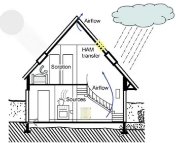
Figure 1 shows an example of a building with just some of the building components, loads and transport processes that should be taken into account when analysing whole-building hygrothermal processes. Most processes occur only locally, but they influence the adjacent building elements such as rooms or structures. The physical conditions also influence each other, such as when the temperature determines the severity of moisture influences. To describe a whole building, it is necessary to set up heat, air, and moisture balances in various elements of the building, e.g., materials, constructions, and rooms. The flows that pass over the interfaces are important.
1.2 Spatial representation of buildings
An ideal situation would be to describe the whole building in very small computational cells. However, this would in
Fig. 1 Building with indoor and outdoor hygrothermal loads
most cases not be needed and would not be computationally efficient. But while some important processes take place in narrow layers of air or building material, other processes in the same building do not require as finely discretized analyses. Figure 2 schematically illustrates heat and moisture accumulation in a building wall. Daily temperature variation on one side of the wall easily penetrates some 20cm into the material, while daily moisture penetration may be just a few millimetres. However, it is important to consider both heat and moisture accumulation in walls with the most appropriate accuracy and computational efficiency when the hygrothermal conditions in rooms and building assemblies are to be predicted. The computational procedures may therefore need to work on different levels of spatial resolution.
1.3 Balances
The hyrothermal performance of a building can be assessed by analysing energy, moisture, and air balances. The hygrothermal balances consider the normal flows of heat by conduction, convection, and radiation; moisture flows by vapour diffusion, convection, and liquid transport; and airflows driven by natural, external, or mechanical forces. However, in whole building heat, air and moisture analyses, combined forms which involve advection heat flows and conversion of latent heat should also be considered. Likewise, the thermal conditions influence very strongly the moisture conditions and natural airflows.
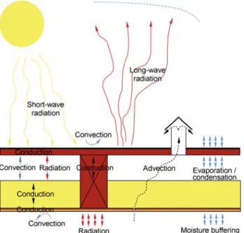
The correct treatment of the interfacial flows at boundaries between control volumes of different type (interface between air and material) is a cardinal point in successful modelling. In practice the interfacial flows may be rather complex, as shown in Fig. 3 for heat transfer.
Fig. 2 Schematic illustration of temperature and moisture buffering in building materials. Hourly profiles resulting from daily excitations at the right-hand boundary
Fig. 3 Roof with different hygrothermal loads and transport processes
1.4 Numerical methods
All simulation tools presented later in this paper are based on some numerical methods for space and time discretization. Possible numerical methods are
Finite Difference Methods (FDM)/Finite Control Volume (FCV) methods,
Finite Element Method (FEM),
Response Factor / Transfer Function method. 1.5 Granularity
Granularity is related to the size of the control volume. In buildings a large variation of granularity is available, from the simplest single-zone modelling (whole building=one zone, called coarse-grained) to CFD modelling (one room=
thousands or millions of zones, called very-finely grained). Intermediate approaches use multi-zone modelling, dividing the building, and even sometimes a room, into a few zones with different air characteristics. Similar classification can apply for the granularity of envelope models: from the sim- plest transfer functions, through 1D, over 2D to 3D modelling using control volume or finite elements techniques.
Whole building tools mainly use two granularity classes: The intermediate-grained models (Fig. 4, left)
v Multi-zone models for air volumes, where several rooms or groups of rooms are represented, each with different characteristics (each zone is supposed perfectly mixed)
v 1D models for the envelope, using control volume or finite element techniques, with typical size of mesh between a few millimetres to several centimetres The coarse-grained models (Fig. 4, right)
v Single-zone models for air volumes, where the whole building is represented as one perfectly mixed zone
v Transfer function models for the envelope, where dynamic heat and possibly mass fluxes are repres- ented without investigating conditions within the envelope
Fig. 4 Levels of granularity for room air
2 Development of whole building HAM models The developments could take place by making entirely new models and tools (Tariku et al. 2006), or by extension
of already existing tools, as for instance:
Extending the existing building simulation tools (to account better for processes linked with the envelope), e.g., Rode and Grau (2003)
Extending the building component simulation tools, e.g., Holm et al. (2003)
A combination of both building simulation and building component simulation tools, e.g., Koronthályová et al. (2004)
Several engineering tools were under development during the period Annex 41 was running, improving their capacities to represent coupled heat, air and moisture response of buildings. Some of them are well known building energy simulation software, such as TRNSYS and EnergyPlus; some have more proprietary use, such as PowerDomus, Clim2000 and SimSPARK. Whole building models take into account location and orientation of the building (climatic zone), various heating, ventilating and air conditioning systems, air infiltration or exfiltration, user behaviour (number of people, activities, moisture and heat production, window ventilation, etc.), and type of room (bathroom, living room, office, etc.). They are mainly situated at the intermediate level of granularity. Some tools are able to support fine level of granularity, for example, by CFD extension of room air modelling. However, these possibilities were not tested in the benchmark cases of the Annex, and therefore are simply mentioned but not described in the following. Management of the overall physical processes for the whole is a matter of not only being able to describe the conditions in the different building elements, but also to correctly account for interfacial transfer and balances.
All tools calculate also moisture level in the indoor air and can account for vapour storage in hygroscopic materials. This last phenomenon is modelled either using simplified (coarse-grained) models or using a detailed description of the heat and mass transfer phenomena in the building envelope. In the last case, moisture level in building elements can also be assessed using the simulation tool. 2.1 General features of whole building HAM models The following text presents the 17 simulation tools that have been used in Annex 41, which are able to simulate whole building HAM performance. This cannot be an exhaustive list of all whole building HAM simulation tools that may exist in different countries. However, as so many as 39 institutions from 19 countries participated in this project, the results give a good overview of today’s simulation capabilities. Each participant was free to choose the tool he or she wanted to use. The choice was frequently based on beforehand knowledge of and experience with the tool. Often the tool was developed by
the participant’s institution, or it had been used there for several years. Moreover the tools were also benchmarked in so-called “Common Exercises” in the Annex, and some improvements were made to the tools during the project. Presentation and discussions of some of the benchmark cases can be found in Woloszyn and Rode (2007), Holm and Lengsfeld (2007).
First, a brief introduction is given for all the models, including relevant references and internet sites when available. Then their main features are contrasted in 8 tables. Evidently, it is impossible to give a full description of 17 simulation tools in a limited number of pages. The aim is to give a general overview of the main features, focusing more on moisture modelling and on the interactions between heat, air and moisture transfer mechanisms. The comparison is based on the descriptions given by the users of the tools with the Annex. As it can be seen in Table 1, the “user” is in some cases from the institution which developed the tool, or in some cases he or she is simply an experienced user.
It must also be stated that some of the models are still under active development. Therefore between the moments of writing this paper and using the information some more or less important improvements might have been made.
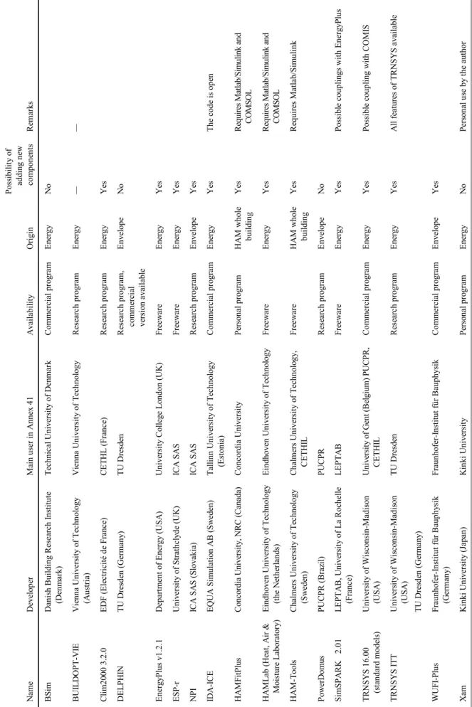
Table 1 gives the origin of the tool and main institutions working with it in Annex 41. It can be seen that eleven tools are used by the developers, and the six remaining by other institutions. Five tools are commercially available, and also five are freeware. Five are only research tools, and two are personal products. Eleven, i.e., the majority, of the tools are originally energy simulation tools, four tools were building envelope simulation tool, and the last two were directly developed as whole building simulation heat-air-moisture tools.
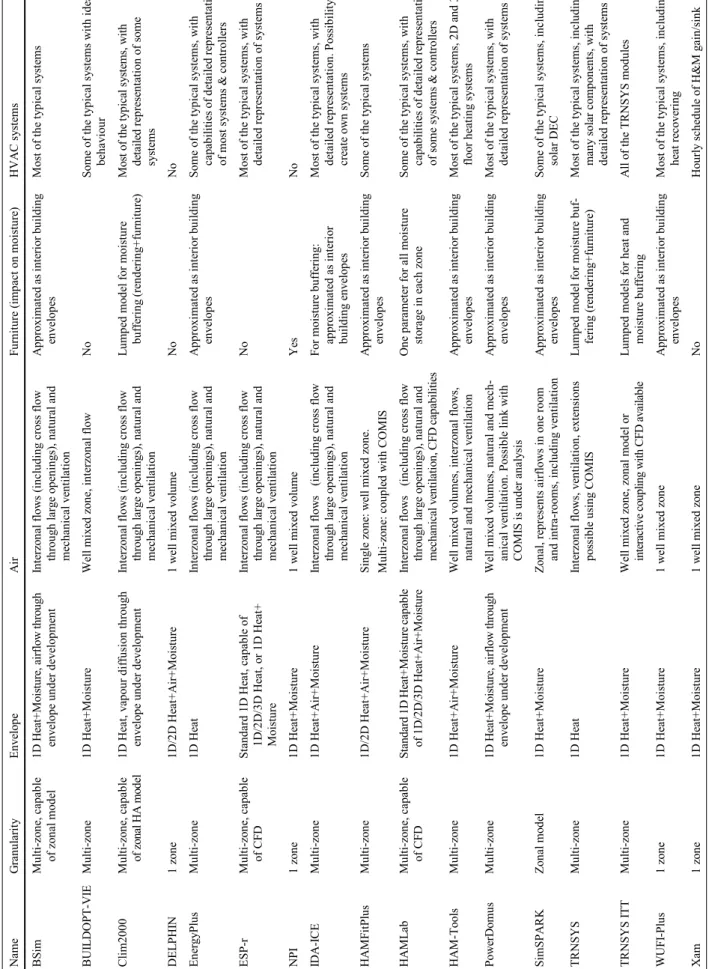
Table 2 gives a first overview of the whole building HAM models implemented in the tools. Most of them can simulate a multi-zone building and heat and mass transfer in the envelope. Four are single-zone tools, and five are able to describe intra-room flows using zonal models or CFD. Of course all of the thirteen multi-zone tools can represent single-zone buildings. Four tools represent in standard version 1-dimensional heat transfer in the envelope, nine 1-dimensional heat and moisture transfer in the envelope and three 1-dimensional heat, air and moisture transfer in the envelope. Finally, only three tools can deal with multi-dimensional coupled transfer at building level. The effect of furniture on indoor relative humidity and temperature is not represented as such, but can be approximated as interior building structures. Some tools use a coarse-grained (lumped) approach. Also, with two exceptions, the tools can represent most of the typical
HVAC systems. However, in most of the tools, the systems are represented in a rather simplified way, where the action of the system on the indoor conditions is represented without detailed description of the HVAC element itself.
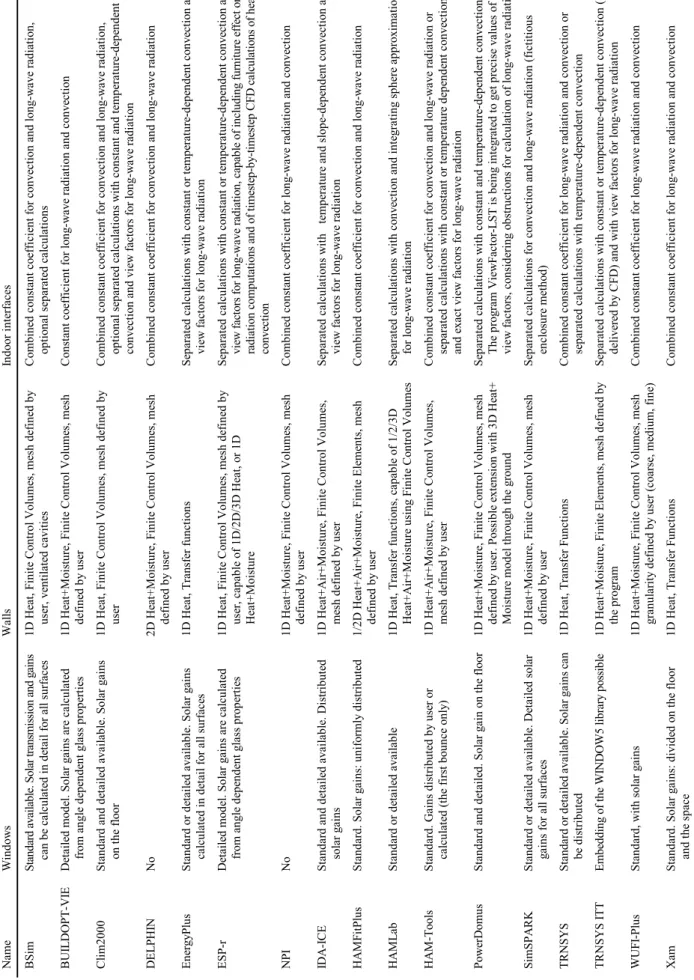
The main elements of the thermal models are contrasted in Table 3. “Standard” window model means use of standard coefficients, such as U-value (heat loss), g (solar gain coefficient) and SC (shading coefficient). Such models also allow for calculations of heat gains according to the position of sun. “Detailed” window model means that the heat transfer is modelled including convection and radiation between and inside the glazing, etc. Some information is also given about the way in which the solar gain is treated. Also wall models are briefly described in Table 3, and especially if they are treated in 1 or 2 dimensions, and what is the main numerical method used (finite control volume —FCV, finite element method —FEM or transfer function). Also principles for computing convection and long-wave radiation are presented in Table 3.
Table 4 details the main characteristics of the moisture models. Thirteen tools include vapour diffusion through the envelope, eight also liquid transport. Moist air movement through the envelope, which is one-dimensional airflow through very permeable constructions excluding cracks, can be simulated by five tools (two more will be available soon), and hysteresis effect of sorption isotherm only by one tool. Also a rather large variety of driving potentials for moisture flow can be seen in Table 4. For example vapour pressure [Pa] is used in nine tools, moisture content [kgmoisture/kgdry_material] in six, relative humidity [—] in four, and vapour concentration [kgvap/m3] in two; some tools using more than one. Moreover, suction pressure [Pa], temperature [℃] and volumetric moisture content [m3/m3] are also used. Some tools use only simplified (coarse-grained) models for moisture buffering.
Table 5 depicts the main characteristics of the airflow models in the 17 tools. Six have only lumped representation of the indoor air, eleven are able to use pressure network to represent more accurately interzonal flows and different ventilation systems, and one tool is a zonal model, where several control volumes are used to describe one room. Most of the multi-zone models and the zonal model include wind and buoyancy effect, also one-way flow through the cracks in the envelope and indoor partitions, as well as cross-flow through large openings. In most of the “lumped” models ventilation and infiltration flows can be defined by the user and added to the energy and moisture balances of the indoor air. Also some tools can be coupled with airflow simulation tools, such as COMIS or CFD, to enhance their modelling capacities.
The main couplings between heat, air and moisture models are represented in Table 6. Of course all tools
represent both latent and sensitive contributions of internal sources. Latent heat due to vapour transfer and to condensation/evaporation process is taken into account in most of the codes; however, in most of them it is either in the envelope or in the HVAC system. Only seven tools are able to take both into account. Also most of the multi-zone models (thirteen) can take into account the impact of both humidity and temperature on air density and therefore on buoyancy. Some tools can also represent moisture and temperature impact on some of the material properties.
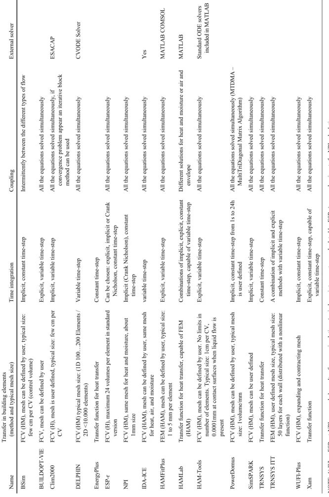
The numerical methods are contrasted in Table 7. Some of the simulation tools use an external solver, such as Matlab for HAMLab, HAM-Tools, and HAMFitPlus. Explicit and implicit methods, as well as constant or variable time-step methods are almost equally distributed. In the envelopes eleven tools use FCV method, four use transfer functions, and two use FEM. If a mesh is used, it is the same for all transfer process (heat, air, and moisture). Moreover in most of the cases (fourteen tools) all equations are simultaneously solved ensuring full coupling between different flows.
All the tools can use variable inputs from weather files; however, not all the information is used. From Table 8 it can be seen that only five tools are able to deal with wind driven rain and eight with heat and moisture transfer through the ground. Wind impact on outdoor convection and on infiltration is rather often represented (twelve tools), as well as the solar shadings from close neighbourhood (twelve tools).
2.2 Introduction of different software
2.2.1 BSim
Rode and Grau (2003 and 2004) present the program BSim2000 (www.bsim.dk), which is a computational design tool for analysis of indoor climate, energy consumption, and daylight performance of building, developed by the Danish Building Research Institute. The core of the system is a common building data model shared by the design tools, and a common database with typical building materials, constructions, windows, and doors. The software can represent a multi-zone building with heat gains, solar radiation through windows (with shadings), heating, cooling, photovoltaic, ventilation, and infiltration, but also transient moisture model for the whole building.
2.2.2 BUILDOPT-VIE
BUILDOPT-VIE is a simulation tool developed at Vienna University of Technology (www.bph.tuwien.ac.at) described in Sofic and Bednar (2007). Development of the first edition of the program started in 2002 and was carried out with
Ta bl e 1 G ene ra l inf or m ation a bout the s of tw ar e Na me De ve lop er Main us er in A nne x 41 A va ila bi lit y Ori gi n Po ssi bi lit y o f adding ne w co m po ne nts Re m ar ks BS im D anis h Buil ding Re se ar ch I ns titute (De nma rk ) T echnical U niv er sity o f D enm ar k Co m m er cial pr og ram En er gy N o BU IL D O PT -V IE V ie nna U niv er sity o f T echno lo gy (A us tri a) Vi en na Un ivers it y of T ec hn ology R es ea rc h p rogra m E nergy — — Cl im 2000 3.2.0 E D F ( E le ctr icité de F rance ) CE T H L ( Fr ance ) Re se ar ch pr og ram E ne rg y Y es D E L PH IN T U D re sde n ( G er m any ) T U D re sde n Re se ar ch pr og ram , co mme rc ia l ve rs io n av ail abl e En ve lo pe N o E ner gy Plu s v1 .2 .1 D ep ar tm en t of E ner gy ( U SA ) U ni ver si ty C ollege L on do n ( U K ) Fr eew ar e E ner gy Y es E SP -r U ni ver si ty of S tr at hc ly de ( U K ) IC A S A S Fr eew ar e E ner gy Y es NPI IC A SA S (Sl ova ki a) IC A SA S R ese arc h p rogra m En ve lo pe Ye s ID A -I C E E Q U A S im ul atio n A B ( Sw ede n) T al linn U niv er sity o f T echno lo gy (E st on ia ) C omme rc ia l p ro gr am E ner gy Y es Th e c od e i s op en H A M Fi tP lu s C on cor di a U ni ver si ty , N R C (C an ad a) C on cord ia Un ivers it y Pers on al p rogra m HA M w hole buil ding Y es Re quir es Matl ab/S im ul ink and CO MS O L HA M L ab (He at , A ir & Mo is tur e L abo ra to ry ) E indho ve n U niv er sity o f T echno lo gy (t he N ethe rl ands ) E indho ve n U niv er si ty o f T echno lo gy Fr ee w ar e E ne rg y Y es Re quir es Matl ab/S im ul ink and CO MS O L HA M -T ools C ha lm ers Un iv ers it y of T ec hn ology (S w ede n) C ha lm ers Un iv ers it y of T ec hn ology , CET H IL Fr eew ar e H A M w hole buil ding Y es Re quir es Matl ab/S im ul ink Po w er D om us PU CP R ( B ra zi l) PU CP R Re se ar ch pr og ram Env el ope N o Si mSPA R K 2 .0 1 L E PTA B , Un iv er si ty o f L a R oc he lle (F ra nc e) L E PT A B Fr eew ar e E ner gy Y es Po ss ib le c ou pl in gs w it h E ner gy Pl us T R N SY S 16.00 (s tandar d m ode ls ) Un iv er si ty o f W isco nsi n-M ad iso n (USA ) U niv er sity o f G ent ( B el gium ) P U CP R, CET H IL C omme rc ia l p ro gr am En er gy Ye s Po ssi bl e co up lin g w it h C O M IS T R NSYS I T T Un iv er si ty o f W isco nsi n-M ad iso n (USA ) T U D re sde n ( G er m any ) T U D re sde n Re se ar ch pr og ram Ene rg y Y es A ll f eatur es o f T RN SY S av ail abl e W U FI -P lu s Fr aunho fe r-In st itut f ür Bauphy si k (G er ma ny ) Fr aunho fe r-Ins titut f ür Bauphy sik Co m m er cial pr og ram En ve lo pe Y es X am K inki U niv er sity ( Japan) K inki U niv er sity Pe rs on al pr og ram E ne rg y N o Pe rs on al us e by the autho r
Ta bl e 2 G ene ra l f ea tur es of w hole building H ea t, A ir a nd Mois tur e m ode ls N am e G ranul ar ity E nv el ope A ir Fu rn itur e ( im pact o n m ois tur e) H V A C s ys te m s BS im Mul ti-zo ne , capabl e of z onal m ode l 1D H eat+Mo is tur e, air fl ow thr oug h en ve lo pe unde r de ve lo pm en t In te rz on al f lo w s ( incl uding cr os s f lo w thr oug h l ar ge o pe ning s) , natur al and m echanical v entil atio n A pp roxi m at ed a s i nt eri or bu ildi ng en velop es M ost o f t he ty pi cal sy st em s B U IL D O PT -V IE Mul ti-zo ne 1D H eat+Mo is tur e W el l m ix ed z one , inte rz on al f lo w N o So m e o f the ty pical s ys te m s w ith ide al be hav io ur Cl im 2000 Mul ti-zo ne , capabl e of z on al H A m od el 1D H eat, v apo ur dif fu sio n thr oug h en ve lo pe unde r de ve lo pm en t In te rz on al f lo w s ( incl uding cr os s f lo w thr oug h l ar ge o pe ning s) , natur al and m echanical v entil atio n L ump ed mo de l fo r mo is tu re buf fe ri ng (r ende ri ng +f ur nitur e) M ost o f t he ty pi cal sy st em s, w ith de tail ed rep res en ta ti on of s om e sy st em s D E L PH IN 1 z one 1D /2D H eat+A ir +Mo is tur e 1 w el l m ix ed v ol um e N o N o E ne rg yP lus Mul ti-zo ne 1D H eat In te rz on al f lo w s ( incl uding cr os s f lo w thr oug h l ar ge o pe ning s) , natur al and m echanical v entil atio n A pp roxi m at ed a s i nt eri or bu ildi ng en velop es So me o f t he ty pi cal sy st em s, w it h ca pab ili tie s of d eta iled re pr es en ta tion of mo st sy st em s & co nt ro lle rs ES P-r Mul ti-zo ne , capabl e of C FD St andar d 1D H eat, capabl e o f 1D /2D /3D H eat, o r 1D H eat+ Mo is tur e In te rz on al f lo w s ( incl uding cr os s f lo w thr oug h l ar ge o pe ning s) , natur al and m echanical v entil atio n No M ost o f t he ty pi cal sy st em s, w it h de ta iled r ep res en ta ti on of s ys tem s N PI 1 z one 1D H eat+Mo is tur e 1 w el l m ix ed v ol um e Y es N o ID A -I C E Mul ti-zo ne 1D H eat+A ir +Mo is tur e In te rz on al f lo w s ( incl uding cr os s f lo w thr oug h l ar ge o pe ning s) , natur al and m echanical v entil atio n Fo r m ois tur e buf fe ri ng : appr ox im ate d as inte rio r buil ding e nv el ope s M ost o f t he ty pi cal sy st em s, w it h de tail ed r epr es en tatio n. P os sibil ity to cre at e o w n sy st em s H A MF itP lu s Mul ti-zo ne 1D /2D H eat+A ir +Mo is tur e Sing le z one : w el l m ix ed z one . Mul ti-zo ne : co upl ed w ith CO MI S A pp roxi m at ed a s i nt eri or bu ildi ng en velop es So me o f t he ty pi cal sy st em s H A ML ab Mul ti-zo ne , capabl e of C FD Standar d 1D H eat+Mo istur e capabl e of 1D /2D /3D H eat+A ir +Mo is tur e In te rz on al f lo w s ( incl uding cr os s f lo w thr oug h l ar ge o pe ning s) , natur al and m echanical v entil atio n, CF D capab iliti es On e p ara me te r for a ll moi st ure sto rag e in e ach z one So me o f t he ty pi cal sy st em s, w it h ca pab ili tie s of d eta iled re pr es en ta tion of so me sy st em s & co nt ro lle rs HA M -T ools M ult i-zon e 1D Hea t+ A ir + M oi st ur e W ell m ixed volu m es , i nt erzon al flow s, natur al and m echanical v entil atio n A pp roxi m at ed a s i nt eri or bu ildi ng en velop es M ost o f t he ty pi cal sy st em s, 2 D a nd 3 D fl oo r h eat in g sy st em s Pow erDom us M ult i-zon e 1D H eat+Mo is tur e, air fl ow thr oug h en ve lo pe unde r de ve lo pm en t W el l m ix ed v ol um es , natur al and m ech-anical v entil atio n. P os sibl e l ink w ith CO MI S is unde r anal ys is A pp roxi m at ed a s i nt eri or bu ildi ng en velop es M ost o f t he ty pi cal sy st em s, w it h de ta iled r ep res en ta ti on of s ys tem s Sim SP A RK Z onal m ode l 1D H eat+Mo is tur e Z onal , r epr es en ts air fl ow s in o ne r oo m and intr a-ro om s, incl uding v entil atio n A pp roxi m at ed a s i nt eri or bu ildi ng en velop es So m e o f the ty pical s ys te m s, incl uding so la r DEC T R N SY S Mul ti-zo ne 1D H eat In te rz on al f lo w s, v entil atio n, e xte ns io ns po ss ibl e us ing CO MI S L ump ed mod el for moi st ure b uf- fe ri ng ( re nde ri ng +f ur nitur e) M ost o f t he ty pi cal sy st em s, i ncl ud in g m any s ol ar co m po ne nts , w ith de ta iled r ep res en ta ti on of s ys tem s T R N SY S I T T Mul ti-zo ne 1D H eat+Mo is tur e W el l m ix ed z one , z onal m ode l o r inte ractiv e co upl ing w ith CF D av ail abl e L um pe d m ode ls f or he at and m ois tur e buf fe ri ng A ll of th e TR N SY S m od ul es W U FI -P lu s 1 z one 1D H eat+Mo is tur e 1 w el l m ix ed z one A ppr ox im ate d as in te ri or b uil di ng en velop es M ost o f t he ty pi cal sy st em s, i ncl ud in g he at re cove ri ng X am 1 z one 1D H eat+Mo is tur e 1 w el l m ix ed z one N o H our ly s che dul e o f H & M g ain/s ink
Ta bl e 3 Som e de ta ils of the the rm al m ode ls N am e W indo w s W al ls Indo or inte rf ace s B Si m Standar d av ail abl e. S ol ar tr ans m is sio n and g ains can be cal cul ate d in de tail f or al l sur face s 1D H eat, F inite Co ntr ol V ol um es , m es h de fine d by use r, v entil ate d cav itie s Co m bine d co ns tant co ef ficie nt f or co nv ec tio n and l ong -w av e r adiatio n, op tio nal se par ate d cal cul atio ns B U IL D O PT -V IE D etail ed m ode l. S ol ar g ains ar e cal cul ate d fr om ang le de pe nde nt g las s pr op er tie s 1D H eat+Mo is tur e, F inite Co ntr ol V ol um es , m es h de fi ne d by us er Co ns tant co ef ficie nt f or lo ng -w av e r adiatio n and co nv ec tio n Cl im 2000 Standar d and de tail ed av ail abl e. S ol ar g ains on th e floor 1D H eat, F inite Co ntr ol V ol um es , m es h de fine d by us er Co m bine d co ns tant co ef ficie nt f or co nv ec tio n and l ong -w av e r adiatio n, op tio nal s epar ate d cal cul atio ns w ith co ns tant and te m pe ratur e-de pe nde nt co nv ec tio n and v ie w f acto rs f or lo ng -w av e r adiatio n D E L PH IN N o 2D H eat+Mo is tur e, F inite Co ntr ol V ol um es , m es h de fi ne d by us er Co m bine d co ns tant co ef ficie nt f or co nv ec tio n and l ong -w av e r adiatio n E ne rg yP lus Standar d o r de tail ed av ail abl e. S ol ar g ains cal cul ate d in de tail f or al l sur face s 1D H eat, T rans fe r f unctio ns Se par ate d cal cul atio ns w ith co ns tant or te m pe ratur e-de pe nde nt co nv ec tio n and vi ew fa ct
ors for lon
g-w av e ra di at io n ES P-r D etail ed m ode l. S ol ar g ains ar e cal cul ate d fr om ang le de pe nde nt g las s pr op er tie s 1D H eat, F inite Co ntr ol V ol um es , m es h de fine d by use r, capabl e o f 1D /2D /3D H eat, o r 1D He at + M oi st ure Se par ate d cal cul atio ns w ith co ns tant o r te m pe ratur e-de pe nde nt co nv ec tio n and vi ew fa ct ors for l on g-wa ve ra di at io n, c ap ab le of i nc lu di ng fu rn itu re e ffe ct on ra diatio n co m putatio ns and o f tim es te p-by -tim es te p CF D cal cul atio ns o f he at co nv ec tio n N PI N o 1D H eat+Mo is tur e, F inite Co ntr ol V ol um es , m es h de fi ne d by us er Co m bine d co ns tant co ef ficie nt f or lo ng -w av e r adiatio n and co nv ec tio n ID A -I C E Standar d and de tail ed av ail abl e. D is tr ibute d so la r g ai ns 1D H eat+A ir +Mo is tur e, F inite Co ntr ol V ol um es , m es h de fi ne d by us er Se par ate d cal cul atio ns w ith te m pe ratur e and s lo pe -de pe nde nt co nv ec tio n and vi ew fa ct
ors for lon
g-w av e ra di at io n H A MF itP lus Standar d. S ol ar g ains : unif or m ly dis tr ibute d 1/2D H eat+A ir +Mo is tur e, F inite E le m en ts , m es h de fi ne d by us er Co m bine d co ns tant co ef ficie nt f or co nv ec tio n and l ong -w av e r adiatio n H A ML ab Standar d o r de tail ed av ail abl e 1D H eat, T rans fe r f unctio ns , capabl e o f 1/2/3D H eat+A ir +Mo is tur e us ing F inite Co ntr ol V ol um es Se par ate d cal cul atio ns w ith co nv ec tio n and inte gr ating s phe re appr ox im atio n for lon g-w av e ra di at io n H A M-T oo ls Standar d. G ains dis tr ibute d by us er o r cal cul ate d ( the f ir st bo unce o nl y) 1D H eat+A ir +Mo is tur e, F inite Co ntr ol V ol um es , m es h de fi ne d by us er Co m bine d co ns tant co ef ficie nt f or co nv ec tio n and l ong -w av e r adiatio n o r se par ate d cal cul atio ns w ith co ns tant o r te m pe ratur e de pe nde nt co nv ec tio n and e xact v ie w f acto rs f or lo ng -w av e r adiatio n Po w er D om us Standar d and de tail ed . S ol ar g ain o n the f lo or 1D H eat+Mo is tur e, F inite Co ntr ol V ol um es , m es h de fi ne d by us er . P os si bl e e xte ns io n w ith 3D H eat+ Mo is tur e m ode l thr oug h the g ro und Se par ate d cal cul atio ns w ith co ns tant and te m pe ratur e-de pe nde nt co nv ec tio n. T he p rogra m Vi ew Fa ct or-L ST is b ei ng i nt egra ted to get p rec is e va lu es of vi ew f acto rs, co nsi de ring o bstr uc tio ns f or cal cul atio n o f l ong -w ave r adia tio n Si mSPA R K St an da rd or d et ai le d a va ila bl e. De ta ile d sol ar ga in s fo r al l su rface s 1D H eat+Mo is tur e, F inite Co ntr ol V ol um es , m es h de fi ne d by us er Se par ate d cal cul atio ns f or co nv ec tio n and l ong -w av e r adiatio n ( fictitio us en clos ur e m et hod ) T R N SY S Stan da rd o r de tail ed av ail abl e. S ol ar gai ns c an be dis tr ibute d 1D H eat, T rans fe r F unctio ns Co m bine d co ns tant co ef ficie nt f or lo ng -w av e r adiatio n and co nv ec tio n o r se par ate d cal cul atio ns w ith te m pe ratur e-de pe nde nt co nv ec tio n T R N SY S IT T E m be dd in g of t he W INDOW 5 li bra ry p ossi bl e 1D H eat+ Mo is tur e, F ini te E le m en ts , m es h de fi ne d by th e p rogra m Se par ate d cal cul atio ns w ith co ns tant o r te m pe ratur e-de pe nde nt co nv ec tio n ( or de liv er ed by CF D ) and w ith v ie w f acto rs f or lo ng -w av e r adiatio n W U FI -Pl us St an da rd , w it h so la r g ai ns 1D He at +M oi st ur e, F in it e C on tro l Vo lu me s, me sh gr anul ar ity de fine d by us er ( co ar se , m edium , f ine ) Co m bine d co ns tant co ef ficie nt f or lo ng -w av e r adiatio n and co nv ec tio n X am Standar d. S ol ar g ains : div ide d o n the f lo or and the space 1D H eat, T rans fe r F unctio ns Co m bine d co ns tant co ef ficie nt f or lo ng -w av e r adiatio n and co nv ec tio n
Ta bl e 4 Ma in c ha ra ct er istic s of the m oisture m ode ls D if fus io n thr oug h the e nv el ope N am e L um pe d V apo ur L iquid Mo is t air H ys te re sis D riv ing po te ntial s f or m ois tur e tr ans fe r B Si m No Ye s No Un de r de ve lo pm ent Y es V apo ur pr es sur e [P a] B U IL DOPT -VI E No Ye s No No No Va po ur p re ssu re [ Pa ] Cl im 2000 D uf or es te l & D al icie ux U nde r de ve lo pm en t No No No M oi stu re c on te nt [k gvap /k gdry _air ] for ai rb orn e flow , va po ur d en si ty for bu ffe ri ng effe ct [ kgva p /m 3 ] and v apo ur pr es sur e [P a] f or 1D H M e nv el ope unde r de ve lo pm en t D E L PH IN N o Y es Y es Y es N o V apo ur pr es su re [P a] fo r v apo ur dif fus io n, m ois tu re co nt en t [ kgva p /k gdry _mate rial ] or w ate r pr es su re [P a] ( cho ice be tw ee n the 2 m ode ls ) f or li quid w ate r E ne rgy Plu s E M PD No No No No R ela ti ve h um id it y [— ] ESP-r — No No No No R ela ti ve h um id it y [ — ] NPI No Ye s Ye s No No R ela ti ve h um id it y [ — ] ID A -I C E Ye s No Ye s No Va po ur d en si ty [ kgva p /m 3] HA M Fi tPlu s No Ye s Ye s Ye s No R ela ti ve h um id it y [ — ] H A ML ab T ransm ittance & adm ittance Y es N o Y es N o V apo ur pr essur e [ Pa] H A M-T oo ls N o Y es Y es Y es N o V apo ur pr es su re [P a] fo r v apo ur f lo w , s uctio n pr es su re [P a] f or li quid f lo w and moi st a ir p re ssu re for a irflow [ Pa ] Pow erDomu s No Ye s Ye s Un de r de ve lo pm ent N o T em pe ratur e and v ol um et ri c co nte nt [m 3/m 3] o r v apo ur pr es sur e [P a] ( cho ice bet w een d if fer en t m od els ) Si mSPA R K No Ye s Ye s No No M oi st ure c on te nt [ kgmo is tu re /kg dr y _mate rial ] and te m pe ratur e T R NSYS C ap ac it an ce “ bu ffe r st ora ge ” No No No No M oi st ure c on te nt [k gmo is tu re /kg dr y _mate rial ] T R N SY S I T T N o Y es Y es N o N o V apo ur pr es su re [P a] f or dif fus io n, w ate r co nte nt [kg mo is tu re /kg dr y _mate rial ] f or liquid tr ans po rt W U FI -P lu s N o Y es Y es N o N o V apo ur pr es su re [P a] and m ois tur e co nte nt [kg mo is tu re /kg dr y _mate rial ] Xa m No Ye s No No No M oi st ure c on te nt [ kgmo is tu re /kg dr y _air ]
Ta bl e 5 M ai n ch aract eri st ic s o f t he ai rf lo w m od el s N am e A ir ne tw or k In cl ude d e ff ects A ir fl ow be tw ee n z one s A ir fl ow thr oug h the w al l Po ss ibl e e xte ns io ns BS im Pr es su re ne tw or k Buo yancy and w ind e ff ects Y es , m ul ti-zo ne m ode l 1D f lo w B U IL D O PT -V IE Fl ow -n et w or k o r p re ss ur e ne tw or k Buo yancy and w ind e ff ects Y es N o Cl im 2000 Pr es su re ne tw or k Buo yancy e ff ect, e ff ects o f v entil atio n sy st em s 1 w ay e x/inf iltr atio ns ; cr os s-fl ow in la rg e op en in gs No DE L PHI N L ump ed — N o 1D /2D f lo w + cr ack f lo w ( fl ow path m ode l) E ne rg yP lus Pr es su re ne tw or k Buo yancy an d w ind e ff ects , pl us pr es su re ef fe cts o f m echanical sy ste m o n na tu ra l flow s 1 w ay e x/inf iltr atio ns ; cr os s-fl ow in la rg e op en in gs No E SP -r Pr es su re ne tw or k Buo yancy and w ind e ff ects , e ff ects o f ve nt ilat io n sy st em s 1 w ay e x/inf iltr atio ns ; cr os s-fl ow in la rg e op en in gs No C FD NPI L ump ed — No No ID A -I C E Pr es su re ne tw or k Buo yancy and w ind e ff ects 1 w ay e x/inf iltr atio ns ; cr os s-fl ow in la rg e op en in gs 1D f lo w H A MF itP lus L um pe d, capabl e o f pr essur e ne tw or k Buo yancy and w ind e ff ects 1 w ay e x/inf iltr atio ns ; cr os s-fl ow in la rg e op en in gs Capabl e o f 1D /2D f lo w in po ro us m edia and cr acks ( fl ow path mo de l) CF D H A ML ab L um pe d, capabl e o f pr essur e ne tw or k Capabl e o f buo ya ncy and w ind e ff ects Capabl e o f 1 w ay e x/inf iltr atio ns Capabl e o f 2D /3D f lo w in cr acks and po ro us m edia CF D w ith CO MS O L H A M-T oo ls L um pe d o r pr es su re ne tw or k Buo yancy and w ind e ff ects , e ff ects o f ve nt ilat io n sy st em s 1 w ay e x/inf iltr atio ns ; cr os s-fl ow in la rg e op en in gs 1D f lo w A ir fl ow m ode l can be us ed as stand-al on e appl icatio n Po w er D om us L um pe d Buo yancy and w ind e ff ects N o 1D f lo w unde r de ve lo pm en t Sim SP A RK In tr a-ro om pr es su re ne tw or k Buo yancy and w ind e ff ects , al so em pir ical la w s f or je ts and pl um es 1 w ay e x/inf iltr atio ns ; cr os s-fl ow in la rg e op en in gs No TR N SY S L um ped — Po ss ibl e de fi ne d by us er N o Co upl ing po ss ibl e w ith CO MI S T R N SY S I T T Pr es su re ne tw or k by T ype 157 (b as ed on C OM IS) Capabl e o f buo ya ncy , w ind e ff ects and de tail ed s im ul atio n o f v entil atio n sy st em s 1 w ay e x/inf iltr atio ns ; cr os s-fl ow in la rg e op en in gs No C FD (F lu en t, PNS) WU FI -P lu s L um pe d — N o In fi ltr atio n in cr acks Xa m L ump ed — Po ss ibl e de fi ne d by us er N o
Ta bl e 6 Ma in c oupling s be tw ee n He at , A ir a nd Moisture m ode ls Na me L ate nt he at Ai rf lo w Mate rial pr op er tie s de pe nding o n tem per at ur e Mate rial pr op er tie s de pe nding o n re la tiv e hum idity BS im I n en ve lo pe s — N one W ate r v apo ur pe rm ea bil ity B U IL D O PT -V IE — T & RH im pact o n air de ns ity and air fl ow N one N one Cl im 2000 In H V A C s ys te m s T & RH im pact o n air de ns ity and air fl ow N one N one DE L PHI N I n en ve lop es — T he rm al co nd uc tiv ity and v apo ur dif fus iv ity Ye s E ne rg yP lus In H V A C s ys te m s T & RH im pact o n air de ns ity and air fl ow N one N one E SP -r In H V A C s ys te m s T im pact o n air de ns ity and air fl ow T he rm al co nductiv ity N one N PI In e nv el op es — W ate r v apo ur pe rm ea bil ity + m ois tur e di ffu si vi ty W ate r v apo ur pe rm ea bil ity ; m ois tur e dif fus iv ity + the rm al co nductiv ity (u si ng so rp ti on is ot he rm) ID A -I C E In e nv el ope s, in H V A C s ys te m s T & RH im pact o n air de ns ity and air fl ow By de fa ul t: no W ate r v apo ur pe rm ea bil ity H A MF itP lus In e nv el ope s, in H V A C s ys te m s T & RH im pact o n air de ns ity and air fl ow O nl y v apo ur pe rm ea bil ity Y es H A ML ab Capabl e o f l ate nt he at in e nv el ope s and in HVA C -sy st ems T & RH im pact o n air de ns ity and air fl ow Po ss ibl e us ing CO MS O L Po ss ibl e us ing CO MS O L HA M -T oo ls In e nv el op es, i n HVA C sy st em s T & R H im pact o n ai r d en si ty an d ai rfl ow A ll A ll Po w er D om us In e nv el ope s, in H V A C s ys te m s T & RH im pact o n air de ns ity and air fl ow Po ss ibl e A ll pr op er tie s by m eans o f s pe cif ic tabl es Sim SP A RK In e nv el ope s, in H V A C s ys te m s T & RH im pact o n air de ns ity and air fl ow Co nductiv ity , H eat capacity f or phas e chang e m ate ri al s T ranspo rt co ef fi cie nts T R N SY S In H V A C s ys te m s T & RH im pact o n air de ns ity and air fl ow ( in CO MI S) No No T R N SY S I T T In e nv el ope s and H V A C s ys te m s T & RH im pact o n air de ns ity and air fl ow Y es Y es W U FI -P lu s In e nv el ope s T & RH im pact o n air de ns ity and air fl ow N one W ate r va po ur pe rm ea bil ity , t he rm al c on-ductiv ity , l iquid, tr ans po rt co ef ficie nts , H eat capacity X am In e nv el ope s, in H V A C s ys te m s T & H R im pact o n air de ns ity and air fl ow N o N o
Ta bl e 7 N um er ic al m ethods us ed in the tools Na me Tr an sf er in b ui ld in g elem en ts (m etho d and ty pical m es h s iz e) T im e inte gr atio n Co upl ing Ex te rn al so lv er BS im FC V ( H M) , m es h can be de fine d by us er , ty pical s iz e: few c m p er C V (c on tr ol volu m e) Im pl icit, co ns tant tim e-ste p In te rm itte ntl y be tw ee n the dif fe re nt ty pe s o f f lo w B U IL D O PT -V IE FC V , m es h can be de fine d by us er E xpl icit, v ar iabl e tim e-ste p A ll the e quatio ns s ol ve d s im ul tane ous ly Cl im 2000 FC V ( H ), m es h is us er de fine d, ty pica l s iz e: f ew cm pe r CV Im pl ic it , va ri ab le t im e-s te p A ll t he eq ua ti on s s olved s im ult an eou sly , i f co nv er ge nce pr ob le m appe ar an ite rativ e bl oc k m etho d can be us ed E SAC AP DE L PHI N FC V (HM ) t yp ic al m es h s ize: (1 D 100… 20 0 E lem en ts / 2D <10.000 e le m en ts ) Va ri ab le t im e-s te p A ll t he eq ua ti on s s olved s im ult an eou sly C V ODE S olver E ne rg yP lus T rans fe r f unctio n f or he at tr ans fe r Co ns tant tim e-ste p E SP-r FC V (H), m axi m um 24 volu m es p er elem en t in s ta nda rd vers io n Can be cho se n: e xpl icit, im pl icit o r Cr ank N icho ls on, co ns tant tim e-ste p A ll t he eq ua ti on s s olved s im ult an eou sly N PI FCV ( H M) , sam e m esh f or he at and m oistur e, abo ut 1mm si ze Im pl icit ( C ra nk N icho ls on) , co ns tant tim e-ste p A ll t he eq ua ti on s s olved s im ult an eou sly ID A -I C E FC V ( H A M) , m es h can be de fine d by us er , s am e m es h for h ea t, a ir, a nd moi st ure va ri ab le t im e-s te p A ll t he eq ua ti on s s olved s im ult an eou sly Yes H A MF itP lu s FE M ( H A M) , m es h c an be de fi ne d by us er , ty pi cal s iz e: 1 to 5 m m pe r e le m en t E xp lic it , va ri ab le t im e-s te p A ll t he eq ua ti on s s olved s im ult an eou sly M A TL A B C O M SOL H A ML ab T ransf er f unctio n f or he at tr ansf er , capabl e o f F E M (HA M ) C om bina tio ns of i m plic it, exp lic it, c on sta nt tim e-ste p, capabl e o f v ar iabl e tim e-ste p Di ffe re nt solu ti on s for h ea t a nd moi st ure or a ir a nd en velop e MA T L A B H A M-T oo ls FC V ( H M) , m es h can be de fine d by us er . N o l im its in num be r o f e le m en ts . T ypical s iz e: 1cm pe r CV , 0.0001m m at co ntact s ur face s w he n l iquid f lo w is pr es en t E xp lic it , va ri ab le t im e-s te p A ll t he eq ua ti on s s olved s im ult an eou sly St an da rd ODE s olvers incl ude d in M A T L A B Po w er D om us FC V ( H M) , m es h can be de fine d by us er , ty pical m es h si ze: 1 volu m e/ m m Im pl icit, co ns tant tim e-ste p f ro m 1s to 24h is us er de fi ne d All t he equ at ion s s olved s im ulta ne ou sl y (M TDM A – M ult iT ri Di agon al M at ri x A lgori th m ) Sim SP A RK FC V ( H M) , m es h can be us er de fine d Im pl icit, v ar iabl e tim e-ste p A ll the e quatio ns s ol ve d s im ul tane ous ly T R N SY S T rans fe r f unctio n f or he at tr ans fe r Co ns tant tim e-ste p A ll the e quatio ns s ol ve d s im ul tane ous ly T R N SY S I T T FE M ( H M) , us er de fine d m es h s iz e, ty pical m es h s iz e: 50 l ay er s f or e ach w al l ( dis tr ibute d w ith a no nl ine ar functio n) A co m binatio n o f im pl icit and e xpl icit m etho ds w ith v ar iabl e tim e-ste p A ll t he eq ua ti on s s olved s im ult an eou sly W U FI -P lu s FC V ( H M) , e xpanding and co ntr acting m es h Im pl icit, co ns tant tim e-ste p A ll the e quatio ns s ol ve d s im ul tane ous ly X am T rans fe r f unctio n E xpl icit, co ns tant tim e-ste p, capabl e o f va ri ab le ti me -st ep A ll t he eq ua ti on s s olved s im ult an eou sly N O T E : 1 ) W hen E SP -r + N PI a re c ou pled , r es ult s of en er gy s im ula ti on s ( as in door a ir te m per at ur e, c alc ula te d b y E SP -r ) a re u sed as inputs f or N PI cal cul atio n. 2 ) FC V : Fi ni te C on tr ol V ol um e; FE M : Fi ni te E le m en t M et ho d; H A M : H ea t − Ai r − Mo is tur e.
Ta bl e 8 Re pre se nta tion of outdoor bounda ry c ondition N am e W ind dr iv en r ain W ind N eig hbo ur ho od G ro und B Si m No Im pa ct on o utd oor c on vec ti on, im pa ct on in fi ltra tion s Sh ad ow s for so la r ra di at io n, loc al p re ssu re c oe ffi ci en ts for w in d Sim pl e r epr es en tatio n H M po ss ibl e B UI L DOPT -VI E No Im pa ct on in fi lt ra ti on s Sh ad ow s for sola r ra di at io n (d et ai le d) Si mp le Cl im 2000 N o Im pact o n o utdo or co nv ec tio n, capabl e o f im pact o n inf ilt ra tio ns No No DE L PHI N Ye s No No No E nergy Plu s No Im pa ct on o utd oor c on vec ti on, im pa ct on in fi ltra tion s Sh ad ow s for sola r ra di at io n He at tra nsfe r E SP-r No Im pa ct on o utd oor c on vec ti on, im pa ct on in fi lt ra ti on s Sh ad ow s for sola r ra di at io n, loc al p re ssu re co effi ci en ts for w in d H eat tr ansf er NPI No No No No ID A -I C E No Im pa ct on in fi lt ra ti on s a nd on ou td oor c on vec ti on Sh ad ow s for s ola r ra di at io n Hea t t ra ns fer HA M Fi tPlu s Yes Im pa ct on o utd oor c on vec ti on, im pa ct on in fi ltra tion s Sh ad ow s f or s ola r r ad iat io n, ad ju st ab le c oef fi ci en ts fo r w ind pr of ile , w ind dr iv en r ain l oad H eat and m oistur e tr ansf er H A ML ab Y es Capabl e of w ind im pact on inf iltr atio n/v entil atio n Sh ad ow s f or s ol ar ra dia tio n, l ocal pr es su re co ef ficie nts for w in d H eat tr ansf er HA M -T oo ls Po ssi bl e w it h si mp lifi ed mo de ls Im pa ct on o utd oor c on vec ti on, im pa ct on in fi ltra tion s Sh ad ow s for so la r ra di at io n, loc al p re ssu re c oe ffi ci en ts fo r w ind, l ocal te m pe ratur e f or r adiatio n H eat and m oistur e tr ansf er Pow erDom us No Im pa ct on o utd oor c on vec ti on, im pa ct on in fi lt ra ti on s Sh ado w s f or so lar r adiatio n H eat and m oistur e tr ansf er Si m SP A RK N o N o Sh ado w s f or so lar r adiatio n H eat and m oistur e tr ansf er T R NSYS No No. In C O M IS i m pa ct on in fi lt ra ti on s a va ila bl e Sh ad ow s for s ola r ra di at ion H eat (g ro und te m pe ratur e as a bo undar y co nditio n) T RN SY S I T T N o Im pact o n o utdo or sur face co ef fi cie nts ( he at and m ois tur e) , im pact o n air fl ow ne tw or k ( T yp e 157) Sh ado w s f or s ol ar r adiatio n 1D he at and m ois tur e tr ans fe r W U FI -Plu s Yes Im pa ct on o utd oor c on vec ti on, im pa ct on in fi ltra tion s Sh ado w s f or s ol ar r adiatio n ( sim pl if ie d) Sim pl e r epr es en tatio n w ith adjus te d T&R H X am N o N o Sh ado w s f or so la r r adiatio n Cal cul ate d as a v er y thick w al l
the focus to optimize the building design for low energy houses. During Annex 41 the tool was further developed to include vapour transfer. It is a multi-zone model which can be used with several hundreds interacting zones. Special attention has been put to prepare the calculation of solar gains through each single window and on the outside of walls by considering the shading by other buildings, overhangs, etc. Transfer in building constructions are cal- culated in one-dimension, based on a FCV method with explicit time integration.
2.2.3 Clim2000
Clim2000 simulation environment has been developed by Electricité de France (Bonneau et al. 1993; Woloszyn et al. 2004). An important feature of Clim2000 is its open structure, allowing combinations of existing components with elements created by the user. A lot of work has gone into validate different Clim2000 models (Lomas et al. 1997; Plathner and Woloszyn 2002). The standard model library includes airflows in multi-zone spaces, energy and moisture sources, and heat transfer through the building envelope. Moisture buffering effect of materials is modelled using a coarse-grained model by Duforestel and Dalicieux (1994).
2.2.4 DELPHIN
The numerical simulation program DELPHIN4 has been developed at the Dresden University of Technology (TUD, www.bauklimatik-dresden.de) as part of research in the field of transport processes in porous building materials. The computer code allows performance analysis of building components under transient climatic boundary conditions and considering moisture and temperature depending material functions. The included material database repres- ents the current research results in material modelling. The new integrated room model allows the calculation of indoor climate in a simplified room as boundary condition for 1D and 2D wall (details see Grunewald 2000; Häupl et al. 2004).
2.2.5 EnergyPlus
EnergyPlus (www.energy-plus.org) is primarily a simulation engine — with a relatively simple user interface, which does not allow the user to input building geometry graphically. More complete interfaces are available from independent third-party developers. Some key capabilities of the simulation engine include variable time steps, con- figurable modular systems integrated with heat balance- based zone simulation, multiple comfort models, daylighting and advanced fenestration, multi-zone airflow, displacement ventilation, flexible system modelling, photovoltaic and solar thermal simulation, and moisture sorption by building
materials using coarse-grained EMPD model (see Crawley et al. 2004; Henninger et al. 2004; Hong et al. 2003).
2.2.6 ESP-r
ESP-r (Clarke 1985 and www.esru.strath.ac.uk) is an integrated modelling system for the assessment of the environmental and energy performance of buildings. It is capable of modelling the heat, power, and fluid flows, within combined building and plant systems when subjected to control actions, as well as visual and acoustic performance of buildings. The package comprises a number of interrelating program modules addressing project management, simulation, results analysis and client report generation. The problem definition exercise is achieved interactively and with the aid of pre-existing databases offering standard construction materials, glazing systems, event profiles, and plant components. Modelling of heat, air, moisture, and electrical power flows can be performed at user determined levels of granularity.
2.2.7 NPI
NPI is a 1D heat and moisture transport model for a system of structures with ideally mixed and time variable ventilated indoor air space (Koronthályová 1998 and 1997). It was developed at the Institute of Construction and Architecture of Slovac Academy of Sciences and is applied in case studies connected mainly with diagnostics of moisture induced damage problems. NPI involves also the depend- ency of material parameters on moisture content. The current version of NPI gradually couples the indoor space only with one type of structure and afterwards, the resulting course of indoor air relative humidity (RH) development is calculated as the weighted mean of the previously calculated indoor air RH developments, in order to ensure fast calculations.
2.2.8 Coupling ESP-r and NPI
An original way of computing whole building energy behaviour is to integrate several simulation tools. Koronthylova et al. (2004) present coupling of NPI and ESP-r, to simulate whole building heat and air transfer, zone airflows, as well as zone heat and moisture transfer in the adjacent building structures (1D) linked with the air and moisture balances in the zone.
The coupling between the tools has been accomplished by the following sequential step algorithm realised in each coupling time (hourly) interval at different levels:
The whole building level —simulation of the 3D heat and air transfer consisting of the modelling of radiation and conduction transfer, together with the air and moisture flows balance of a zone, without hygric inertia (ESP-r)
Zone level —simulation of heat and moisture transfer in the adjacent envelope structures (1D) linked with the air and moisture balance of the zone (NPI)
Post-processing or coupling of the ESP-r and NPI enables to exploit the capabilities of both particular tools.
2.2.9 IDA-ICE
IDA Indoor Climate and Energy (www.equa.se) is a tool for simulation of building energy consumption. The indoor air quality (IAQ) and thermal comfort is presented by Kalamees (2004) and Sahlin et al. (2004). IDA-ICE covers a large range of phenomena, such as the integrated airflow network and thermal models, CO2 and moisture calculation, vertical temperature gradients and daylight predictions. To calculate moisture transfer in IDA-ICE, the common wall model RCWall should be replaced with HAMWall, developed by Kurnitski and Vuolle (2000). The moisture transfer is modelled by one moisture-transfer potential, the humidity by volume.
2.2.10 HAMFitPlus
HAMFitPlus is developed during the Annex 41 project by Tariku et al. (2006). This whole building hygrothermal simulation tool is used to assess the durability, indoor conditions (occupant comfort), and also energy efficiency of a building in an integrated manner. The model includes heat, air and moisture transfer across building envelope components and the indoor air taking into account the indoor heat and moisture generations, HVAC system, and dynamic HAM interaction with building envelope components.
2.2.11 HAMLab
A new integrated heat, air and moisture modelling toolkit in MATLAB named HAMLab (sts.bwk.tue.nl/hamlab) has been presented by van Schijndel (2007) and de Wit (2006). The implemented numerical model consists of a continuous part for the HVAC system and the indoor climate, solved with a variable time step, and a discrete part, solved with a time step of one hour for the external climate. Combining the MATLAB/Simulink modelling toolkit with COMSOL allows comprehensive modelling of a room with 2D/3D HAM transport in constructions or 2D airflow.
2.2.12 HAM-Tools
HAM-Tools (www.ibpt.org), presented by Sasic Kalagasidis (2004) and Sasic Kalagasidis et al. (2007), is a modular building simulation software, developed in Sweden by Chalmers University of Technology in collaboration with Technical University of Denmark. The main objective of this tool is to obtain simulations of transfer processes related to building physics, i.e., heat and mass transport in
buildings and building components in operating conditions. The model solves heat, air and mass balance equations in an air zone (supposed to be fully mixed) and in the building enclosure, considering air, vapour and liquid transport in one dimension.
2.2.13 PowerDomus
PowerDomus (Mendes et al. 2003; Mendes and Philippi 2005; www.pucpr.br/LST) solves heat and moisture transfer in walls simultaneously according to a method developed by Mendes et al. (2002). The model has an integrated simulation of HVAC systems (Barbosa and Mendes 2007). Seven levels of calculation complexity in HAM models are possible (e.g., with or without moisture transfer, constant or variable material hygrothermal properties, vapour pressure or moisture content driving potentials).
2.2.14 SimSPARK
SimSPARK (Wurtz et al. 2006; Mora et al. 2004; Mendoca et al. 2005) uses zonal models to represent intra-room airflow as well as different models to describe heat and moisture transfer across the building zone envelope, with two of them taking into account moisture adsorption / desorption by building materials. The resulting set of non-linear coupled equations is solved simultaneously by the object-oriented simulation environment, SPARK (gundog.lbl.gov). SimSPARK is suited to parametric studies and complex problems, and can be linked to other simulation tools like EnergyPlus.
2.2.15 TRNSYS
The TRNSYS program (TRaNsient SYstems Simulation, sel.me.wisc.edu/trnsys) is a building energy performance simulation tool with a modular structure. Some other tools (COMIS, Matlab/Simulink, etc.) can be directly linked to the software. The TRNSYS library includes many of the components commonly found in thermal and electrical energy systems, such as solar systems (solar thermal and photovoltaic systems), low energy buildings and HVAC systems, renewable energy systems, cogeneration, fuel cells, etc. It also allows for predictions of the indoor relative humidity, including some buffering effect of materials, using the penetration depth model (Klein et al. 2004).
2.2.16 TRNSYS ITT
TRNSYS ITT is a tool for building simulation that is based on the framework of TRNSYS 14.1 (Klein et al. 2004; Perschk and Meinhold 2007). The wall-model in “Type 56” (module for a multi-zone building) is replaced by a new one (Type 158). The new type is able to consider coupled heat and moisture transfer in the envelope. Diffusion,
liquid water transport, phase changing and ice formation are taken into account, as well as a geometrical model for realistic representation of shading and long-wave radiation.
2.2.17 WUFI-Plus
Holm et al. (2003) describe a holistic model called WUFI- Plus (www.wufi.de) based on the hygrothermal envelope calculation model WUFI (Künzel 1994). WUFI-Plus combines a model for heat and moisture transfer in the building envelope with a whole building simulation model for energy calculations. It takes into account moisture sources and sinks inside a room, moisture exchange with the envelope due to capillary action, diffusion and vapour absorption and desorption as a response to the exterior and interior climate conditions, as well as the thermal parameters.
2.2.18 Xam
Xam is a heat and moisture simulation program which has been developed by Iwamae (Iwamae et al. 1999; Iwamae 2004). It calculates the annual variations of temperature and humidity in a building and the energy needed for heating and cooling. The numerical model depends on the simultaneous heat and moisture (humidity ratio) transport in porous 1D wall. The user can get information about the sensitivity of the properties of materials on the temperature and humidity variations.
3 Common exercises
Six different common exercises were carried out in the project to make inter-model comparison and to stimulate the participants to extend the capabilities of their models. In some common exercises, it was attempted to model the results from experimental investigations, such as climate chamber tests (for example Lenz 2006). In Common Exercise 1, it was attempted to model the so-called BESTEST building of IEA SHC Task 12 & ECBCS Annex 21 (Judkoff and Neymark 1995), see Fig. 5. The original BESTEST building was extended with moisture sources and material properties for moisture transport and is described more in details in Rode et al. (2006). Constructions were altered so they were monolithic, the material data were given as constant values or as functions, and the solar gain through windows was modelled in a simplified way.
For all cases there is an internal moisture gain of 500g/h from 9:00−17:00 every day. The air change rate was always 0.5ach. The heating and cooling control for all the non-isothermal cases specified that the indoor temperature should be between 20 and 27℃, and that the heating and cooling systems had infinite power to ensure this. The system was a 100% convective air system, and the thermostat was regulating on the air temperature.
Fig. 5 BESTEST base case building
The first cases were very simple, so analytical solutions could be found. The results from 14 different simulation tools are plotted against the analytical solution in Figs. 6 and 7, showing good agreement between solutions. These results gave an increased belief that it was possible to predict the indoor RH with whole building hygrothermal calculations.
Fig. 6 Indoor relative humidity from analytical predictions with isothermal exposure. Construction surfaces are tight
Fig. 7 Indoor relative humidity from analytical predictions with isothermal exposure. Construction surfaces are open
In the second and the more realistic part of the exercise the building was exposed to a real outdoor climate as represented by the test reference weather of Copenhagen, and a simplified modelling of radiation was adopted. The results shown in Figs. 8 and 9 illustrate the difficulty of carrying out the whole building hygrothermal modelling, as some deviations were quite significant. The differences in the thermal simulation could not explain all the deviation, as it was present also for the case with constant indoor temperature. Some deviations seemed to be the result of how well the solar gains were calculated. Thanks to whole building HAM modelling, some local results for moisture conditions could also be compared: Fig. 9 shows the relative humidity inside the roof structure. For most of the tools, the results agreed with one another, which indicate that the simulations perform correctly when it comes to the calculation of moisture transport in the building enclosure.
Fig. 8 Indoor vapour pressure from numerical calculations with
varying indoor temperature in the range 20 to 27℃, but no
external radiation
Fig. 9 Relative humidity in the top of the roof from numerical calculations with varying indoor temperature in the range 20 to
27℃. Solar and long-wave radiation is included
All Common Exercises executed as part of Annex 41 Subtask 1, illustrated the complexity of the whole building hygrothermal modelling: it was possible to find a con- sensus among the solutions with different calculation models only for an extremely simple case.
On the other hand, these results also underline the importance of this type of exercises: the existing codes are tested for their suitability for whole building hygrothermal simulation, and new codes have been created, including upgrading and further development of existing codes to be able to handle the moisture simulation. Moreover, the presented results underline some strong points of whole building HAM simulation tools: they are able to simul- taneously predict indoor climate, as well as energy consumption, together with local hygrothermal conditions within the building elements.
4 Conclusion and perspectives
An overall ambition of IEA Annex 41 has been to stimulate the development of information and analytical tools about how a whole building works in terms of its hygrothermal conditions. This has involved modelling of several physical processes pertaining to coupled flow of heat, air, and moisture. And it has involved different building elements at various levels: its spaces, the building envelope with its materials, the interior building structures and furnishing, the system for heating, ventilating and air conditioning, occupants and equipment, and finally the exposure to the exterior environment. The actual challenge in whole building HAM modelling is to ensure a good balance between the many different physical phenomena which interact with each other, rather than to develop models that focus too much on mainly one phenomenon. For example, in most of the existing programs, if moisture is well modelled, then the energy model is rather simple; or if energy is rather well calculated, then moisture behaviour is treated in a simplified way—if not neglected. In this field a lot of progress has been made and encour- aging outcomes resulted from this collaborative project.
The state-of-the-art of existing HAM models and tools at whole building levels, as well as the five Common Exercises designed and performed throughout the course of the Annex, are the major outcome of this collaborative work. The common exercises are well documented and can be successfully used by the scientific community as benchmark tests for model validation and development. 4.1 Specific developments in the used whole building
HAM tools
been to enhance existing building simulation tools to be better able to predict the moisture behaviour of buildings. Common Exercises contributed to the validation of 17 tools. Besides this, one completely new tool was developed during the Annex (HamFitPlus). The most straightforward outcome is the enhancement of moisture transfer modelling for building envelopes:
Coupled heat and vapour transfer models for 1D flow have been developed in energy simulation tools (Clim2000, BUILDOPT-VIE), and also a new module for coupled heat-air-moisture transfer is under development and testing in EnergyPlus.
The dependency of water vapour permeability on moisture content was introduced in NPI.
An additional model based on vapour pressure was included in PowerDomus.
Modelling of multi-layer walls was achieved in SimSPARK.
Common Exercises have demonstrated the importance of correct evaluation of heat and airflow balances for moisture calculations. Indeed, relative humidity is highly temperature dependent, and airflows are significant for the transport of moisture. Therefore heat and air transfer models were enhanced in some tools. Long-wave radiative heat exchange between internal surfaces using exact view factors was introduced in HAM-Tools and PowerDomus. Moreover in PowerDomus the modelling of heat transfer through complex glazing was improved as well as computations of convective heat transfer and central HVAC system model. Models were introduced in BSim for outdoor ventilated cavities, and for 1D airflow through building envelopes. Pressure network modelling was introduced in BUILDOPT-VIE and HAMLab.
Extensive use of simulation tools encouraged optimisation of numerical methods for NPI and WUFI-Plus.
Concerning representation of intra-room airflow, a lumped model was introduced into the building envelope model DELPHIN. CFD modelling was tested within HAMLab, and two other building envelope models were coupled with more detailed room air simulations (NPI with ESP-r, for whole building aspects, and Xam with STREAM for CFD distribution).
4.2 Main results in whole building HAM modelling As a general principle about the impact of moisture on whole building energy response, different researchers agree that the first and essential step is to correctly represent the moisture balance, including vapour absorption and desorption from hygroscopic surfaces. In some practical applications, when only an estimation of the indoor climate is of
interest, this can be done using simplified models for moisture buffering.
However, when the moisture level in constructions is of interest, the investigations require use of coupled heat and mass transfer models to describe the complex physics in walls. An encouraging fact is that different potentials for moisture transfer can be successfully used (relative humidity, vapour pressure, moisture ratio by volume, etc.). Also models that represent heat and simple vapour diffusion in envelope parts, without considering liquid migration or hysteresis in sorption isotherm, can give correct estimation of hygrothermal building response in many practical applications. Indeed their results were similar to those of more complex tools in the common exercises performed. The importance of interactions in whole building HAM response was also shown. The levels of relative humidity in the indoor air were strongly dependent not only on the moisture transfer between air and construction and moisture sources, but also on the correct analysis of airflows and of temperature levels, depending upon proper energy balances.
Nevertheless, correct estimation of the initial conditions and good choice of mesh size and of time step size can have significant impact on the predicted solutions.
4.3 Outlook for the future
The experience from the Common Exercises, as well as parameter study performed and some of the free papers presented by partners of the project indicate that there is still a lot to do. The future work in the field of whole building HAM modelling should concentrate on two complementary issues:
Consolidate and apply the existing knowledge
Improve and extend the comprehension of physical phenomena and their modelling
As described in this paper, many models and simulation tools exist, which are able to represent the HAM behaviour of buildings at different levels of granularity and complexity. However, there is still a need to execute more validation cases, possibly as a comparison with measurement data, experiences from practice and field tests. Such validation should be complemented with extensive sensitivity studies. The objective would be to consolidate the knowledge on the limits of the models and to better point out difficulties in existing models, such as the choice of parameters in simplified modelling, or correct grid size.
The models are valuable tools to better understand real problems and to provide correct solutions. Therefore some effort should also be done in “bringing simulations into
![Table 4 Main characteristics of the moisture models Diffusion through the envelope Name Lumped VapourLiquid Moist airHysteresisDriving potentials for moisture transfer BSim No Yes No Under developmentYesVapour pressure [Pa] BUILDOPT-VIENo Yes No N](https://thumb-us.123doks.com/thumbv2/123dok_us/9768846.2860145/9.892.112.767.154.1135/characteristics-moisture-diffusion-vapourliquid-airhysteresisdriving-potentials-developmentyesvapour-buildopt.webp)