Towards vision-based control of cable-driven parallel
robots
Tej Dallej, Marc Gouttefarde, Nicolas Andreff, Mica¨
el Michelin, Philippe
Martinet
To cite this version:
Tej Dallej, Marc Gouttefarde, Nicolas Andreff, Mica¨
el Michelin, Philippe Martinet. Towards
vision-based control of cable-driven parallel robots. IROS: International Conference Intelligent
Robots and Systems, Sep 2011, San Francisco, United States. IEEE/RSJ, pp.2855-2860, 2011.
<
hal-00691562
>
HAL Id: hal-00691562
https://hal.archives-ouvertes.fr/hal-00691562
Submitted on 26 Apr 2012
HAL
is a multi-disciplinary open access
archive for the deposit and dissemination of
sci-entific research documents, whether they are
pub-lished or not.
The documents may come from
teaching and research institutions in France or
abroad, or from public or private research centers.
L’archive ouverte pluridisciplinaire
HAL
, est
destin´
ee au d´
epˆ
ot et `
a la diffusion de documents
scientifiques de niveau recherche, publi´
es ou non,
´
emanant des ´
etablissements d’enseignement et de
recherche fran¸
cais ou ´
etrangers, des laboratoires
publics ou priv´
es.
Towards vision-based control of cable-driven parallel robots
Tej Dallej, Marc Gouttefarde, Nicolas Andreff, Mica¨el Michelin and Philippe Martinet
(LASMEA - LIRMM - TECNALIA)Email:{tej.dallej}@lasmea.univ-bpclermont.fr http://wwwlasmea.univ-bpclermont.fr
Abstract— This paper deals with the vision-based control of cable-driven parallel robots. First, a 3D pose visual servoing is proposed, where the end-effector pose is indirectly measured and used for regulation. This method is illustrated and validated on a cable-driven parallel robot prototype. Second, to take into account the dynamics of the platform and using a Cartesian pose and velocity estimator, a vision-based computed torque control is developed and validated in simulation.
I. INTRODUCTION
Parallel mechanisms have a closed-loop structures, with several kinematic chains connecting the base and the mobile platform [1], [2]. Most existing parallel robots are designed with rigid legs which cannot exceed a certain length. A major drawback of such designs is their limited workspace.
Parallel cable-driven robots are a particular type of par-allel robots which consist essentially of a moving platform connected in parallel to a base by cables [3]. The length of the cables is adjusted to control the position and orientation of the platform. The cable tensions are related to forces and torques at the moving platform. Parallel cable-driven robots have several advantages over more conventional rigid-link robots. The main one is maybe scalability: Cables with small to very large lengths are easily stored on spools or drums allowing to build parallel cable robots with a workspace of global dimension ranging from a few centimeters to tens of meters or more [4]. Depending on their size and practical realization, they may also be less expensive, easier to build, reconfigure and, when thin cables or wires are used, safer and non intrusive. These useful properties make cable-driven parallel robots good candidates for several applications, e.g., robotic cranes [5] or automated construction systems [6] and human-scale force-feedback haptic systems [7]. Paral-lel cable-driven robots also have drawbacks such as the unilateral character of actuation (the cables can only pull) which, for some applications, make actuation redundancy compulsory [3].
The control and the modeling of cable-driven parallel robots are complex due to the flexible nature of the cables. In [8], the authors proposed controllers for the cable suspended robot using Lyapunov theory and feedback linearization. In this work, there is no measure of Cartesian position. The pose (position and orientation) of the mobile platform can be estimated through the forward kinematics but the latter is generally difficult to solve and the measures of cable lengths by means of active joint variables may be inaccurate due notably to cable elongations. Another solution is to use
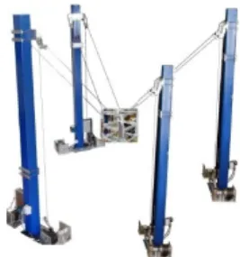
ad-Fig. 1. The LIRMM/Tecnalia ReelAx8 robot
ditional passive cables setting up an independent metrology [9] and whose layout is such that the forward kinematics has closed-loop solutions. This solution increases however the probability of cable collisions and adds constraints to the mechanical design.
Another control strategy was presented in [10]. The pro-posed method uses a nonlinear feed-forward control laws in cable length coordinates and compute an optimal tension distribution.
In [11], the authors proposed to control a 6-DOF cable robot by means of recursive algorithm to generate reachable domains for motion of the robot end-effector taking into account input constraints. However, continuous tendon forces are not guaranteed. Moreover, due to the complexity of the dynamics of the robot general motion, rotations are not con-sidered in this work. Ref.[12] proposes a real-time algorithm for tendon force calculation, without iterative steps. This approach guarantees the continuity of force distribution.
Several control laws are proposed in [13], [14], [15] using visual servoing techniques [16], [17], [18]. They prove that the use of computer vision in the feedback control loop simplifies the kinematic models by introducing additional sensors into the parallel robots and thus yields easier control. For the control of cable-driven parallel robots, visual servoing methods can also be a good alternative, since it closes the control loop over the vision sensor. External sensing of the end-effector pose in the feedback signal replaces advantageously the forward kinematic model. The perception models are simpler than the kinematic models and contain less unmodelled physical phenomena.This is especially useful in cable-driven robots because the flexibility of the cable.
Therefore, the contribution of this paper is to present vision-based control of a cable-driven parallel robot. Sec-tion II presents the kinematic modeling of the generic
configuration of cable-driven mechanisms. This method is applied to the ReelAx8 parallel robot (Fig.1). Section III-A presents a first method for the vision-based control of cable-driven parallel robots which is 3D pose visual servoing. Then, the vision-based computed torque control approach is presented in Section III-B. Section IV presents an experi-mental validation of the 3D pose visual servoing as applied to the ReelAx8 robot. Section V shows simulation results of the vision-based computed torque control. Conclusions are finally given in Section VI.
II. VISION-BASED KINEMATICS
In the kinematic modeling the notations given in Table I are used.
• i= 1..k denotes the driving cables, where k is the number of cables.
• Boldface characters denote vectors. Unit vectors are under-lined.
• Fb = (O,xb,yb,zb), Fe = (E,xe,ye,ze) and Fc =
(Oc,xc,y
c,zc) denote the base, end-effector and camera
reference frames, respectively. • ivis vectorvexpressed inFi.
• qi defines the motorized joint anglei. • li defines the length of cablei. • ϑi is the tension applied by cable i.
• iTj =
i
Rj itj
0 1
is the homogeneous matrix associ-ated to the rigid transformation fromFi toFj.
• iτjis the cartesian velocity of the origin ofFjexpressed in
Fi.
• X, X˙ and X¨ are a representation of the end-effector pose, velocity and acceleration, respectively.
• Γis the vector of motor torques. • M+ is the pseudo-inverse ofM. • Mcis the estimation ofM.
• [a]×is the cross-product matrix of vectora.
TABLE I
NOTATIONS USED THROUGHOUT THE PAPER.
ReelAx8 is a 6-DOF cable-driven parallel robot (Fig.1). It has a moving platform (end-effector) connected to a fixed base by 8 driving cables of varying length li and cable
tensionϑi,i∈1..8(k = 8). Each cable (Fig.2) is attached to
the moving platform at point Bi and extends from the base
at point Ai.
We can imagine that ReelAx8 robot as a Gough-Stewart platform [19], [20] which is turned upside down. When the cables are tensed and considered massless and inextensible, the kinematic modeling of Gough-Stewart platforms and of parallel cable-driven robot are very similar.
Fig.2 shows a generic configuration of cablei. The cable-driven parallel robot is equipped with a camera defined by its reference frameRc and a pattern defined by frameRp.
We consider Rf a fixed reference frame attached to the
base andRma mobile reference frame attached to the
end-effector. There are two visual servoing configurations. In the first, (eye-in-hand), the camera attached to the end-effector (Rc=Rm) observes a pattern fixed with respect to the base
frame (Rp =Rf). In the second one (eye-to-hand), Rp is
a mobile reference frame (Rp =Rm) andRc is the fixed
reference frame (Rc =Rf). Mobile platform Cable i Ai Bi Re Rm E O Rb Rf Tm f Tf b Te m Base ui
-
ui mFig. 2. Generic configuration of cablei
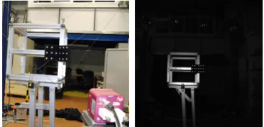
Fig. 3. From left to right: a photograph of ReelAx8 mobile platform and the initial position of the end-effector, seen from the camera.
Introducing ui the unit vector pointing from Ai to Bi
(Fig.2), one can write:
m−−−→A
iBi=limui (1)
This equation can be expressed in any Euclidean reference frame. Hence, it can be expressed in the mobile frameRm,
which simplifies the adequation between the instantaneous inverse kinematic model and the regulated error in the visual servoing task. In the sequel, we consider the ReelAx8 robot equipped with a camera and a pattern in eye-to-hand configuration (Fig.3).
Time differentiating (1) and usingmuTi mu˙i= 0 yield:
˙ li= d(m−−−→AiBi T ) dt mu i= d(mBi−mAi)T dt mu i (2)
where Bi is time invariant in the mobile frame Rm, (2)
yields: ˙ li=− d(mA i)T dt mu i=− d(mR ffAi+mtf)T dt mu i (3)
Thus, according e.g. to [13], [21], the instantaneous inverse kinematic model of a parallel cable-driven robot, relating the Cartesian velocity mτm = mτm/m∗ = ( mVm mΩm )T of the mobile frame to the time
˙ l=mDinvm mτm (4) with mDinv m = muT 1 (mB1×mu1)T .. . ... muT k ( mB k×muk) T (5)
where themBi is a constant (calibration) parameter.
The motorized joint angle vectorqof the robot are linearly related to the time derivatives of cable lengths and can be computed as: ˙ q= 1 rc ˙ l (6)
whererc is the radius of the drums collecting the cables.
Note that the direction of each cable can be written as
mu i = m−−−→A iBi km−−−→A iBik = mB i−mAi km−−−→A iBik (7) Being given that mA
i = (mRffAi+mtf), the
instan-taneous inverse kinematic model (4) depends on the pose
mT
f, the rigid transformation between camera and pattern,
and on the constant (calibration) parametersfAi andmBi.
III. VISION-BASED CONTROL A. 3D pose visual servoing
1) Interaction matrix associated to the pose:
Consider Rm andRm∗ the desired and the current mobile
frame positions, respectively. For the control of the robot end-effector pose, in [22], [23], [24], [25] the authors present the following visual primitives:
s= ( st
sw
) (8)
In our case, st = mtm∗ is the translation error between
Rm and Rm∗ and sw =uθ, where u is the axis and θ is
the angle of the rotation matrixmR
m∗. The visual primitive
sis thus 0 when the current frame reaches the desired one (s∗=0).
As shown in [25], [26], we can write:
˙ st=−mVm/m∗+ [mtm∗]×mΩm/m∗ d(uθ) dt =−Lw mΩ m/m∗ (9) where • Lw=I3−θ2[u]×+ 1− sinc(θ) sinc2(θ 2) [u]2 × • sinc(θ) =sin(θθ)
The time derivative of sis:
˙
s=Lsmτm (10)
wheremτmis the end-effector Cartesian velocity and Ls is the interaction matrix expressed as:
Ls = −I3 [mtm∗]× 03 −Lw (11) Notice that in the case of s = 0, the interaction matrix simplifies intoL0=−I6.
2) Control law:
To regulate the error between the current primitive vectors
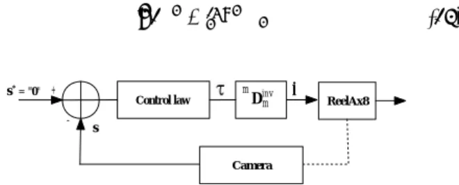
and the desired ones∗=0, one can consider the exponential decay s˙ = −λs. The vision-based control (Fig.4) can then be expressed as:
mτ
m=−λLcs +
s (12)
Let us note that only information from the vision sensor are used to define the relation betweensand the end-effector Cartesian velocitymτm[26].
Note also that the instantaneous inverse kinematic model can be written as:
˙ l=mD[inv m mτ m (13) Control law Dm + -s s*= "0" l. ReelAx8 m inv Camera
Fig. 4. 3D pose visual servoing of a cable-driven parallel robot
This method allows the execution of a classic and simple robotic task in the Cartesian space.
B. Vision-based computed torque control
In section III-A, we presented a vision-based kinematic control, where the end-effector pose is measured using a camera and used for regulation. This method simplifies the control and replaces joint sensors. However, it does not take into account the dynamics of the robot.
The contribution of this section is to present a vision-based computed torque control for ReelAx8 cable-driven parallel robot (Fig.5). PD + -X X* + X* -+ + X* . ^ .. X^. Simplified dynamics (Fph p)T J Camera -W+ + + fnul uc
Fig. 5. Vision-based computed torque control of a cable-driven parallel robot
In this section, we consider that the center of mass corresponds to the end-effector originE.
1) Simplified dynamics:
In this section, we take into account only the dynamic of the moving platform. The actual ReelAx8 prototype is not a large dimension mechanism. So, the mass of each cable can be neglected to have a simplified dynamics.
The gravitational force applied on the end-effector at the pointEismpg.mpandgare respectively the mass and the
gravity acceleration vector. Let us denote fI
e the moment of inertia of the mobile
platform about its center of mass expressed in the fixed frame Rf.
Using the Newton-Euler’s laws, one can write the applied and inertia force wrench exerted at pointEand expressed in the fixed frameRf as:
kF e= Fp ηp Rf = mp(g−at) −fI efΩ˙e−fΩe×(fIefΩe) (14) where Fp is the sum of the applied and inertia forces on
the end-effector, ηp is the inertia moment, at is the linear
acceleration and fΩ
e is the angular velocity of the
end-effector expressed in the fixed frame Rf.
2) Equation of motion:
Noting that a cable can only pull the end-effector (Fig.2), one can write the cable tension at pointBi:
ϑi=−ϑifui (15)
where ϑi =k ϑi k is tension of cable i which is to be
nonnegative.
The wrench applied by cableiat the reference pointEis:
ki= ϑi ηBi + f −−→ EBi×ϑi ! Rf (16)
Assuming that the moment ofϑi at pointBi isηBi=0,
we obtain using (15) an (16): ki=ϑiWi (17) where Wi= −fu i −f−−→EB i×fui ! = −fu i −fR eeBi×fui ! (18) To keep platform in equilibrium, one can write the relation between the applied and inertia forces wrench kF e (from
(14)) and cable tensions wrenches as:
kF e +
k
X
i=1
(ki) = 0 (19)
It can be also written as:
kF e + Wϑ = 0 (20)
whereW = (W1, ..., Wk),ϑ= (ϑ1, ..., ϑk)T and k is the
number of cables.
Finally, one can compute the vector of cable tensions as:
ϑ = −W+kF e (21)
Then, neglecting the inertia of the drums, the motor torques can be computed using:
Γ = rcϑ (22)
whererc is the reel motor radius of the drums.
As shown in Fig.5, a vector of forces fnull lying in the
nullspace of matrix W can be added to the tension vector computed in (21) in order to try to keep all tensions positive
[3] during motion but without changing this latter. The computation of fnull may be an issue which is beyond the
scope of this paper. In the simulation of Section V, fnull is
taken equal to the zero vector.
3) Combining measure and computed torque control: Using a fast exteroceptive measure [15], [27], we can reduce the complexity of control schemes. The proposed computed torque control in Fig.5 needs the estimation of cartesian pose and velocity of the moving platform. They can be measured by vision, which is used directly in the control loop to compensate dynamics in real time.
The controller is a standard computed torque controller in the Cartesian space, namely a PD and a feedforward con-troller (see Fig.5). The output of whichuc is homogeneous
to an acceleration. The control output can thus be fed into (14) to compute the desired wrench.
The cable tensions are related to the moving platform dynamics by W, which can be estimated only by using information from vision (the direction fu
i and fRe) and
constant calibration parametereB i.
IV. EXPERIMENTAL VALIDATION
The 3D pose kinematic visual servoing approach of section III-A has been implemented and applied to ReelAx8 cable-driven parallel robot. An off-the-shelf
0P hotonf ocusM V −D1024−T rackCam0 camera is used
to estimate the pose [27] of the mobile platform.
The camera is attached to the base frame and a pattern is fixed to the end-effector (eye-to-hand configuration). The camera is placed in front of the robot so that it can cover a large amount of the workspace (Fig.3).
Fig. 6. Evolution of the cartesian error.
In an experiment, the ReelAx8 robot is asked to reach the desired position from the initial configuration (Fig.3)
ct
m = (−0.0181, −0.0744, 1.4248)T (m) as the pattern
position andθ= 0as the rotation angle. The desired position is obtained from the reference position by a translation of −20 mmalong they
c axis of the camera.
Fig.6 and Fig.7 show that the errors converge to 0 as expected, from an initial cartesian error to a steady state one(' 1.5 mm).
Notice that the error curves are exponentials and that the 3D trajectory (Fig.8) of the pattern is linear in camera frame, which confirms the properties of the 3D pose visual servoing.
Fig. 7. Evolution of the cartesian velocities.
Fig. 8. Evolution of the pattern trajectory.
V. SIMULATION RESULTS
The vision-based computed torque control is validated by means of a ReelAx8 cable-driven parallel robot simulation. All kinematic parameters are expressed in the fixed frame Rf.
Fig. 9. Evolution of the end-effector trajectory.
In the simulations presented below, we choose the carte-sian initial position bte = (0, 0, 0)T and orientations
α=β=γ= 0.
Fig.9 and Fig.10 show the reference rectangular motion. It is composed of translations along the three axis xb, yb
andzb. The last part of the reference trajectory (Fig.10) is
composed of rotations around the three axis xb,yb andzb.
To show the robustness of the approach, we added noise to the estimation of the cartesian pose bTe and velocity.
Fig. 10. Desired position and orientation of the end-effector.
Fig. 11. Evolution of the translation errors.
Fig. 12. Evolution of the orientation errors.
Consequently, we define at each time a sample random noise for translation and operational velocity, with maximal value of0.2mm and2 mm/s, respectively. We also added noise to the rotation angle and angular velocity, with maximal amplitude of0.01◦ and of 0.1◦/s, respectively.
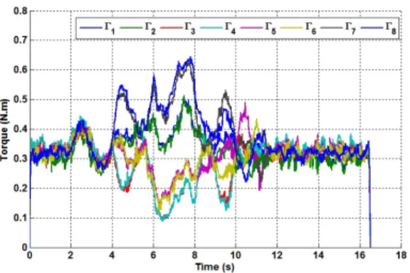
Fig.11, Fig.12 and Fig.13 show a potentially good robust-ness. Table II presents mean values and standard variances (deviations) of the error vector norm.
Mean value Standard variance Translation error (mm) 0.4 0.1
Orientation error (°) 0.0225 0.0038 Operational velocity error (mm/s) 1.1 3.6
Orientation velocity error (°/s) 0.0616 0.2069 TABLE II
Fig. 13. Evolution of motor torques.
VI. CONCLUSION
This paper proposed methods to control a cable-driven parallel robot using a visual target and a calibrated camera. The use of computer vision in the feedback simplifies the kinematic modeling by introducing additional sensors into the robot and thus yields easier control.
Using a 3D pose kinematic visual servoing method, the end-effector pose is used for regulation. This method val-idated on a cable robot prototype, ReelAx8, robot differs from standard control in the joint space by the fact that the forward kinematic model is never used in the control.
It has to be noticed that the pose is estimated in the task space which is the Cartesian space of the robot. Conse-quently, we wanted to fuse a 3D pose and velocity visual tracking [27] and a dynamic control of cable-driven parallel robots.
Doing so, we have introduced a second approach: a vision-based computed torque control. The presented method was validated on a ReelAx8 robot simulator. It is performed with noise added to show the validity of the approach.
The next step in this work is to implement the vision-based computed torque control on the ReelAx8 robot and to extend the method to large dimension cable-driven parallel robots.
VII. ACKNOWLEDGMENT
The financial support of the ANR (grant 2009 SEGI 018, CoGiRo project) is greatly acknowledged.
REFERENCES
[1] J.P. Merlet. Parallel robots. Kluwer Academic Publishers, 2000. [2] I. A. Bonev. The true Origins of Parallel Robots. ParalleMIC: the
Parallel Mechanisms Information Center, January 2003.
[3] R. G. Roberts, T. Graham, and T. Lippitt. On the inverse kinematics, statics, and fault tolerance of cable-suspended robots. Journal of Robotic Systems, 15:581–597, 1998.
[4] N. Riehl, M. Gouttefarde, C. Baradat, and F. Pierrot. On the determi-nation of cable characteristics for large dimension cable-driven parallel mechanisms. In IEEE Transactions on Robotics and Automation, Alaska, USA, May 2010.
[5] J. Albus, R. Bostelman, and N. Dagalakis. The nist robocrane. J. Robot. Syst., 10(5):709–724, 1993.
[6] R. L. Williams II, M. Xin, and P. Bosscher. Contour-crafting-cartesian cable robot system concepts: Workspace and stiffness comparisons.
ASME Int. Des. Eng. Tech. Conf. Comp. Inf. Eng. Conf., 2008. [7] M. Ishii and M. Sato. A 3d spatial interface device using tensed
strings. Presence, 3(1):81–86, 1994.
[8] A.B. Alp and S.K. Agrawal. Cable suspended robots: design, planning and control. In IEEE Transactions on Robotics and Automation, volume 4, pages 4275 – 4280, Washington, May 2002.
[9] R. L. Williams II, B. Snyder, J. Albus, and R. Bostelman. Seven-dof cable-suspended robot with independent metrology. ASME Int. Des. Eng. Tech. Conf. Comp. Inf. Eng. Conf., 2004.
[10] S. Fang, D. Franitza, M. Torlo, F. Bekes, and M. Hiller. Motion control of a tendon-based parallel manipulator using optimal tension distribution. InIEEE/ASME Transactions on Mechatronics, volume 9, pages 561 – 568, September 2004.
[11] S.R. Oh and S.K. Agrawal. Generation of feasible set points and control of a cable robot. IEEE Trans. on Robotics, 22(3), June 2006. [12] L. Mikelsons, T. Bruckmann, M. Hiller, and D. Schramm. A real-time capable force calculation algorithm for redundant tendon-based parallel manipulators.IEEE International Conference on Robotics and Automation, pages 3869 – 3874, May 2008.
[13] T. Dallej, N. Andreff, Y. Mezouar, and P. Martinet. 3d pose visual servoing relieves parallel robot control from joint sensing. In Proceed-ings of the IEEE International Conference on Intelligent Robots and Systems, IROS’06, pages 4291–4296, Beijing, China, October 2006. [14] N. Andreff, T. Dallej, and P. Martinet. Image-based visual servoing
of Gough-Stewart parallel manipulators using legs observation. Joint Issue of IJCV and IJRR on Vision and Robotics, 26(7):677–687, July 2007.
[15] F. Paccot, N. Andreff, and P. Martinet. A review on dynamic control of parallel kinematic machine: theory and experiments. International Journal of Robotics Research, 28(3):395–416, 2009.
[16] L. Weiss, A. Sanderson, and C. Neuman. Dynamic sensor-based control of robots with visual feedback. InIEEE Trans. on Robotics and Automation, volume 3, October 1987.
[17] B. Espiau, F. Chaumette, and P. Rives. A new approach to visual servoing in robotics. IEEE Trans. on Robotics and Automation, 8(3):313–326, June 1992.
[18] S. Hutchinson, G.D. Hager, and P.I. Corke. A tutorial on visual servo control. IEEE Transactions on Robotics and Automation, 12(5):651– 670, October 1996.
[19] V. Gough and S. Whitehall. Universal tyre test machine. In Int. Technical Congress F.I.S.I.T.A, volume 117, pages 117–137, London, May 1962.
[20] D. Stewart. A platform with six degrees of freedom. InUK Institution of Mechanical Engineers Proceedings, volume 180, pages 371–386, London, 1965.
[21] N. Andreff and P. Martinet. Kinematic modelling of some parallel manipulators for control purposes. InThe first European Conference on Mechanism Science, EuCoMes’06, page 6 pp on CDROM, Austria, February 2006.
[22] W. J. Wilson, C. C. Williams Hulls, and G. S. Bell. Relative end-effector control using cartesian position-based visual servoing. IEEE Transactions on Robotics and Automation, 12(5):684–696, 1996. [23] P. Martinet, N. Daucher, J. Gallice, and M. Dhome. Robot control
us-ing 3d monocular pose estimation. InProceedings of the Workshop on New Trends in Image Based Robot Servoing, IEEE/RSJ International Conference on Intelligent Robots and Systems, IROS’97, pages 1–12, Grenoble, France, September 1997.
[24] N. Daucher, M. Dhome, J.T. Laprest´e, and G. Rives. Speed command of a robotic system by monocular pose estimate. InIEEE International Conference on Intelligent Robots and Systems, IROS’97, volume 1, pages 55–62, Grenoble, France, September 1997.
[25] B Thuilot, P. Martinet, L Cordesses, and J. Gallice. Position based visual servoing: keeping the object in the field of vision. InIEEE International Conference on Robotics and Automation, pages 1624– 1629, Washington, USA, May 2002.
[26] E. Malis, F. Chaumette, and S. Boudet. 2 1/2 d visual servoing. InIEEE International Conference on Robotics and Automation, vol-ume 15, pages 238–250, Detroit, USA, April 1999.
[27] R. Dahmouche, N. Andreff, Y Mezouar, and P. Martinet. 3d pose and velocity visual tracking based on sequential region of interest acquisition. InIEEE International Conference on Intelligent Robots and Systems,IROS’09, pages 5426 – 5431, St. Louis, MO, October 2009.