Li, W., Feng, C., Zhang, L., Xu, H., Cao, B. and Imran, M. A. (2020) A scalable
multi-layer PBFT consensus for blockchain. IEEE Transactions on Parallel and Distributed
Systems, (doi: 10.1109/TPDS.2020.3042392).
There may be differences between this version and the published version. You are
advised to consult the publish
er’
s version if you wish to cite from it.
http://eprints.gla.ac.uk/226620/
Deposited on: 2 December 2020
Enlighten
–
Research publications by members of the University of Glasgow
http://eprints.gla.ac.uk
A Scalable Multi-layer PBFT Consensus for
Blockchain
Wenyu Li, Chenglin Feng, Lei Zhang,
Senior Member, IEEE
, Hao Xu, Bin Cao,
Member, IEEE
and Muhammad Ali Imran,
Senior Member, IEEE
Abstract—Practical Byzantine Fault Tolerance (PBFT) consensus mechanism shows a great potential to break the performance
bottleneck of the Proof-of-Work (PoW) based blockchain systems, which typically support only dozens of transactions per second and require minutes to hours for transaction confirmation. However, due to frequent inter-node communications, PBFT mechanism has a poor node scalability and thus it is typically adopted in small networks. To enable PBFT in large systems such as massive Internet of Things (IoT) ecosystems and blockchain, in this paper, a scalable multi-layer PBFT based consensus mechanism is proposed by hierarchically grouping nodes into different layers and limiting the communication within the group. We first propose an optimal double-layer PBFT and show that the communication complexity is significantly reduced. Specifically, we prove that when the nodes are evenly distributed within the sub-groups in the second layer, the communication complexity is minimized. The security threshold is analyzed based on faulty probability determined (FPD) and faulty number determined (FND) models respectively. We also provide a practical protocol for the proposed double-layer PBFT system. Finally, the results are extended to arbitrary-layer PBFT systems with communication complexity and security analysis. Simulation results verify the effectiveness of the analytical results.
Index Terms—PBFT, communication complexity, node scalability, consensus mechanism, blockchain.
F
1
INTRODUCTIONT
He consensus mechanism/algorithm, which orderstransac-tions and guarantees the integrity with consistency of the blockchain across geographically distributed nodes, is of impor-tance to blockchains, which is the backbone of groundbreaking decentralized ledger technology and cryptocurrency. It provides secure, accountable, and immutable and low-cost solutions. Thus, it has shown great potential in various sectors such as financial services, energy trading, supply chain management, Internet of Things (IoT), etc [1].
The consensus algorithms largely determine the performance of distributed system especially for blockchains, such as trans-action throughput, latency, node scalability, security level, etc. Depending on application scenarios and performance require-ments, different consensus algorithms can be considered. In the case of a permission-less public blockchain, nodes are allowed to join or leave the network without permission and authentication; therefore proof based algorithms such as Proof-of-Work (PoW) [2], Proof-of-Stake (PoS) [3], and their variants are commonly used in many public blockchain applications, where the cryp-tocurrency such as Bitcoin is the most well-known one. Proof based algorithms are designed with excellent node scalability performance through nodes competition, which is essential to deal with the double-spending problem. However, they could be very resource demanding. For instance, recently published estimates of bitcoin’s electricity consumption are wide-ranging, on the order of
20-80 TWh annually, or about0.1% 0.3%of global electricity
consumption [4]. Also, these consensus mechanisms have other limitations, such as long transaction confirmation latency and low throughput. For instance, the Transaction Per Second (TPS) is generally limited to 7 in Bitcoin and about 15 in Ethereum, while the transaction confirmation delay is typically as considerable
W. Li, C. Feng, L. Zhang (Corresponding author), H. Xu, M. Imran are with James Watt School of Engineering, University of Glasgow, United Kingdom (e-mail:{2357476L, 2357707F}@student.gla.ac.uk; {Lei.Zhang, Muhammad.Imran}@glasgow.ac.uk; [email protected]). B. Cao is with Beijing University of Posts and Telecommunications of China (email: [email protected]). The work was supported in part by the UK EPSRC under grant number EP/S02476X/1.
as 10 minutes in Bitcoin and 15 seconds in Ethereum [5]. It is worth pointing out the computational requirement of Proof-based consensus varies from one to another, the notable examples of non-computing Proof-based consensus is InterPlanetary File System (IPFS), a distributed file system uses the concept of proof-of-space/ space-time [6]. Though, Proof-based consensus has been mostly seen in the applications of public blockchain, it has a limited generic distributed system and blockchain coverage, as it is still incrementally resource demanding, and the search of voting-based consensus for blockchain and new generation distributed system is imminent.
Unlike the public blockchain, the private and consortium blockchains prefer to adopt lighter consensus protocols such as PBFT, Paxos [7] and Raft [8] [9] to reduce the amount of computational power and improve the transaction throughput [10]. They have been widely used in general distributed systems for data synchronization, meanwhile, their property is also critically important to the application scenarios of the blockchain-enabled IoT ecosystem, which is typically composed of low cost and low power devices. Though some private chain suitable consensus only enables the Crash Fault Tolerance (CFT) [8], as it does not protect the integrity of transactions from malicious attacks, but they are acceptable for private blockchain where the nodes are trusted.
1.1 PBFT applied to blockchain
To protect distributed systems from malicious users, Practical Byzantine Fault Tolerance (PBFT) was proposed in [11] as an improved and practical protocol based on original Byzantine Fault Tolerance (BFT) [12] [9]. Comparing to the Proof based consensus such as PoW, where the security threshold is51%, i.e., absolute secure transaction can be achieved if the malicious user(s) occupies no more than half of the overall resource, PBFT requires
the number of malicious users under33%of total participants to
ensure the system immune from the malicious attacks [11]. PBFT is favoured for private and consortium chains, thanks to the lower complexity and low energy consumption, which is par-ticularly important for wireless IoT applications [13]. A promising
advancement of PBFT can be found in Hyperledger development [14], part of Hyperledger business blockchain frameworks, which has been adopted by tech giants like IBM or Wall Street Fintech, such as J.P. Morgan [15].
1.2 Motivations
Though PBFT has shown good performance in terms of latency, resource requirement and nodes complexity, the node scalability, which is a metric to measure how well the network reflects the capacity of the system to handle the increasing number of nodes, is a bottleneck of PBFT since it relies on heavy inter-node communications. Thus, from the communication complexity perspective, the PBFT based blockchain hardly scales up to 100 nodes [16].
Variant PBFT-based consensuses have been proposed to solve the problem of poor scalability. For example, PBFT with short-lived signature [17], minimizes the consensus time for signature verifying. Another significant evolution path is sharding, where shards have their own consensus group; hence the transactions can be confirmed within a short time because of the smaller size network [18] [19]. However, the trade-off includes increased com-munication costs and lowered security levels. For instance, every shard keeps its own data, which is not shared with other shards. In the case of users requesting contracts on several shards, inter-node communications go up quickly. Meanwhile, putting segments of data into different repositories without proper redundancy and recoverability is risky. Losing control of any individual shard will interrupt the blockchain completely, either causing untraceable and irreversible records to future records or forking the chain from the breaking point [20].
The communication complexity issues in the PBFT system is due to the exhaustive peer to peer communication among the nodes. To reduce the cost of communication, intuitively, one can construct a hierarchical multi-layer PBFT by refraining the communication within their layers or groups. The sub-consensus can be performed per group, and the overall sub-consensus can be defined as exceeds the number of groups achieved the sub-consensus. This multi-layer PBFT system model is initially proposed in [21], providing a brief analysis of communication complexity based on a particular case. However, there are still many challenges to be addressed before this idea can be applied in a real system. Firstly, the complexity analysis derived in the [21] cannot be applied to generic situations as it is developed under the premise that the number of nodes in each sub-group is equal. To better represent the practical situation, detailed analysis should be provided considering various node allocation scenarios. Also, the security analysis in [21] is derived under the hypothesis that faulty nodes only exist in the bottom layer, which does not apply to real situations where faulty nodes are randomly distributed into all layers. Therefore, new security analysis should also be provided to verify the reliability of multi-layer PBFT system. Finally, to ensure liveness and safety of the network, a new complete protocol is also needed.
1.3 Contributions and organizations
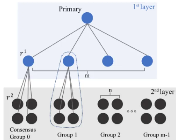
In this paper, we first propose a double-layer PBFT system,
as shown in Fig. 1, where we havem replicas in the first layer
andn sub-layer replicas in the second layer, which give a total
number of1 +m+mnnodes in the network. Then we extend
this system model to a more generalX-layer case (X >2, X 2I) to analyze and compare communication complexity in multi-layer systems. The security analysis shows that the security performance
Primary 1 2 Consensus Group 0 Group 1 m n Group 2 1st layer 2nd layer Group m-1
Fig. 1. Topology of the proposed double-layer PBFT system. (Note that we give double-layer system as an example here, the idea proposed in this paper can be extended to arbitrary-layer PBFT.)
is improved over time, and the consensus algorithm accommodates
at mostbn
3c⇥b
m
2cfaulty nodes to ensure the absolute safety of
the system under malicious attacks. Meanwhile, onlym2+mn2
inter-node messages, instead ofO(Z2)messages in a traditional single-layer PBFT network consensus, are required.
However, it is inevitable that the scalability is improved at the cost of a longer delay as the consensus-reaching process goes through more than one layer. As a result, the proposed multi-layer PBFT would not be appropriate for systems such as some financial scenarios in consortium blockchain which requires both node scalability and low latency transaction. On the contrary, in other applications such as blockchain-enabled scenarios with massive IoT devices connection, where scalability is a bottleneck but not latency, multi-layer PBFT provides a solution with greatly improved node scalability while protecting the system from ma-licious attacks [22] [23] [24]. For instance, blockchain can be used to play an important role for tracking and managing all elements involved in supply chain from raw materials to the final products to ensure the quality of the manufacturing [25]. Given the fact that there are many player within the system, traditional single layer PBFT based blockchain is hard to scale up. With multi-layer PBFT, the suppliers could be divided into groups and layers and consensus can be reached among them to provide reliable information for different parties and ensure the efficiency of manufacturing.
Note that, in such hierarchical scenarios, the consensus is reached in a network with biased rights in different layers. Indeed, we have seen the most consensus models in blockchain have treated their nodes with the equality, however, it is also common to find examples of inequality in real-life for upper level scalability and availability; for example, the practice of liquid democracy, has shown a good influence on social stability and performing the best interests of represented members, in which case, the participants are still in active power after the upper-tier delegate is elected. Another common example of master/slave (leader/follower) model of data storage has produced promising results regarding the availability and I/O performance. Moreover, a lack of flexibility and liquid can be added with the proposed dynamic multi-layer design. The multi-layer PBFT and the advanced system together form a rolling, robust and flexible consensus for not only digital
distributed systems, but also prompts real-life impacts. From this point of view, the proposed PBFT consensus serves as a viable solution to the current society to a trade-off between an efficient but low secure, centralized architecture and a highly secure but low efficient distributed one.
To summarize, this paper makes the following contributions
• This paper first introduces a novel double-layer PBFT
model. This model is scalable since it reduces the
inter-node communications toC ⇡ 1.9Z43, comparing to the
traditional PBFT system ofO(Z2).
• Second, the analytical security performance of the
pro-posed system is derived. It proves that under certain conditions, the maximum number of faulty nodes can
increase frombm 3ctob n 3c⇥b m 2c.
• Third, a new double-layer PBFT protocol is introduced,
based on which consensus can be reached among nodes in different layers.
• Finally, a generalX-layer PBFT model is proposed, which
is proven to have the minimum communication complexity
reduced to linearC=16Z3 16when the network depth is
maximized toXmax. Additionally, the security threshold
is derived.
The rest of the paper is organized as follows. Section 2 reviews the related work. In Section 3, the double-layer PBFT model is proposed. Then, the communication complexity is analyzed and compared to the original PBFT. In Section 4, the security threshold is derived based on the double-layer system. A general
X-layer system is proposed and analyzed in Section 5. Section 6
proposes the protocols for double-layer PBFT system and Section 7 concludes the paper.
2
RELATED WORKVariant consensus algorithms have been designed for permis-sioned blockchain to provide safety under trustless environment with different performances [26]. Practical Byzantine Fault Toler-ance (PBFT) [11] is one of the most popular State Machine
Repli-cation (SMR) technology, which provides 1
3 optimal tolerance
under malicious attacks with low latency. In recent years, with the growing interest in blockchain, many new protocols based on SMR are proposed. InThe Next 700 BFT Protocols, the author present a method to simplify the designing of new protocols by introducing Abortable Byzantine faulT toleRant stAte maChine replicaTion (Abstract) as a new way to illustrated BFT [27]. Results show
that the proposed protocol by using Abstract provides a better
performance in terms of both latency and throughput.
Apart from the application in permissioned blockchain, the concept of quorum certificate is also borrowed in Ethereum Casper to provide safety for Ethereum 2.0 [28]. It is an extra mechanism on top of PoS and serves as a finality gadget. The Casper does not generate the block but determines the sequence of blocks on chain. The designated replicas (validators in Ethereum) votes for a parent-children relationship for two collections of blocks and
form a quorum certificate granted by more than 2
3 of replicas. Considering that Ethereum 2.0 updates rapidly, it is difficult to draw a conclusion on the application of shards and Casper. The sharding may sacrifice safety and increase communication complexity, and the actual implementation of Casper in Ethereum 2.0 also affects it.
One problem PBFT protocols may encountered is the difficulty to implement. BFT-SMART is so far the most popular open-source library for BFT-SMR application based on Java, filling the gap between the literature work and practical implementation [29].
Evaluation shows that the throughput of BFT-SMART reaches more than 80,000 TPS. Also, although it is simpler than other BFT implementing systems, it still contains 13.5K lines of Java code, which is much more complicated than the implementing systems for Paxos [26].
Another bottleneck of PBFT is its scalability. As mentioned in the introduction, the communication complexity limits the performance of protocols. Former researchers have also proposed various solutions. The HotStuff leverages threshold signature to re-duce communication complexity [30]. In each phase, the primary broadcasts messages and each replica responses a valid message with a partial signature. The primary collects them responses
with partial signature more than 2
3 replicas and combine into a
digital signature. This signature is broadcasted by replica again, which serves as a quorum certificate. Unlike HotStuff, the multi-layer PBFT proposed improves node scalability by reorganizing network structure, where the threshold signature can also be ap-plied to further reduce the communication complexity. Moreover, it is noticeable that as the network scales up, the primary in HotStuff has to collect and broadcasts an increasing number of messages and combines more partial signatures. This workload can be barked down by implementing our tree-like structure. Also, the pace of HotStuff is affected by the primary since it waits for the aggregation of partial signature to advance.
3
COMMUNICATION COMPLEXITY OFDOUBLE-LAYER PBFT
3.1 Original single-layer PBFT
Before introducing the system model of double-layer PBFT, the protocol and communication complexity of original single-layer PBFT [11] are briefly analyzed in this subsection. Fig. 2 shows the protocol diagram of the original single-layer PBFT. As an example, we assume there is one primary node and three state machine replicas. The consensus is triggered by a client sending
a request to the nodes’ header (Replica0). Then consensus will
be operated among the nodes, and if an agreement is reached among the replicas, the new record will be committed to the blockchain, vice versa. The whole consensus process includes
three stages pre prepare, prepare and commit as shown
in Fig. 2. On receiving the request from the client, the primary
node (i.e., Replica 0) broadcasts a pre prepare message to
the other nodes. In prepare and commit stages, all replicas
send messages to check the validity of received messages. In each stage, a minimum number of consistent messages are required for stepping into the subsequent stage.
The consensus is technically reached when the commit phase is successful among the majority of non-faulty nodes. Specifically, the client must receive at leastf+1replies (f denotes the number of faulty nodes in the group) from the nodes to validate the final consensus with a total number of3f+1replicas. This ensures that at least one non-faulty replica replies to this operation. In the case of the client fails to collectf+ 1 replies, the client may resend the request to primary for retry. Upon receiving the same request again, if the consensus is already reached on the commit phase, replicas just resend the final stage messages. If the consensus is not reached, the network goes over the protocol again.
From Fig. 2, we can see that PBFT is a communication demanding protocol. Given the total node number Z, the original
single-layer PBFT requiresO(Z2)times of inter-node
communi-cations to reach consensus. Obviously, the system is not scalable
since the complexity burden is non-affordable when Z is large
In the next, a scalable multi-layer PBFT system and protocol is proposed to reduce the communication complexity. The per-formance analysis and protocol design of a double-layer system will be introduced first, and then the arbitrary-layer system will be proposed in Section 5.
request pre-prepare prepare commit reply
Cliet Replica 0 Replica 1 Replica 2 Replica 3
Fig. 2. Single-layer PBFT consensus processing [11].
3.2 Protocol overview of double-layer PBFT
In the double-layer PBFT protocol, scalability is improved by recursively inserting the PBFT consensus algorithm between commit and reply phases as the sub-layer algorithm. The higher layer forms a certificate, which proves that the consensus was reached. With this certificate, a node in the first layer initiates a PBFT consensus reaching process among second layer nodes.
As illustrated in Fig. 1, there are m replicas and a primary
node in the first layer. Each replica in the first layer forms a consensus group withnsub-layer replicas in the second layer. The
primary invokes a new operation by multicastingpre prepare
messages to replicas in the first layer with information about this
operation. The replica accepts validpre preparerequests and
step into prepare phase by multicastingpreparemessages within
the first layer. If one replica receives no less than 2f identical
prepare messages from other first-layer replicas, that operation is prepared on this replica. A prepared replica then multicasts
commitmessages among first-layer replicas.
Similarly, this operation is committed after collecting2f iden-ticalcommitmessages. At this point, this particularly first-layer replica is considered as the primary node in its consensus group
and starts consensus reaching by multicasting newpreprepare
messages to its sub-layer nodes. For instance, in Fig. 1, a
commit-ted noder1sendspre preparemessages to noder2and other
replicas inConsensusGroup0. Second-layer replicas repeat the
process mentioned above until the commit phase. Finally, all committed replicas in the second layer send reply messages to primaries, and primaries reply to the client. This protocol will be stated in detail in Section 6.
3.3 Communication complexity analysis of double-layer PBFT
The double-layer PBFT model is proposed in Fig. 1, where the first-layer leader controlsmreplicas, each of which serves as
a primary node of then sub-layer replicas in the second layer.
Therefore, there are 1 +m+mn nodes in the system. Note
that here we assume each sub-group in the second layer has the same number of nodes, and a generic case will be discussed in Proposition 11. Based on this, the communication complexity can be calculated as the following proposition.
Proposition 1. For a double-layer PBFT system withmreplicas in the first layer andnsub-layer replicas in each sub-group, the
communication complexityCto reach consensus is
C= (m+ 1)2+m(n+ 1)2. (1) Proof is derived in Appendix.
In the next, we aim to find the optimal setup of a double-layer
system with givenZ nodes to provide the lowest communication
cost. When the overall number of nodes Z is given to form
a double-layer PBFT, we can assign either larger groups (i.e., smallermand largern) or a larger number of groups (i.e., larger
mand smallern).Proposition 9gives the best grouping algorithm in terms of minimizing the communication complexity.
Proposition 2. For a double-layer system containingZnodes in total, the minimum communication complexity can be achieved whenn equals to the nearest integer to the real positive root of following equation:
n3+ 3n2+n= 2Z 1, (3nZ 4
3 ). (2)
Proof is derived in Appendix.
Note that, Proposition 9is based on the assumption that the
system is full, in other words, the number of sub-layer replicas in each sub-group is equal.
Proposition 9 provides with a pragmatic method to design a
double-layer PBFT system with minimumC. In the next, we try
to find a direct function of C vs. Z so that the communication
complexity of any double-layer system can be estimated analyti-cally.
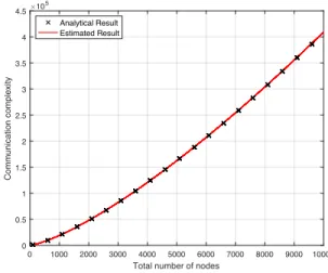
Proposition 3. When m and n are fixed by optimal allocation and the system is full, the relationship between communication complexityCand total node numberZcan be written as
C⇡1.9Z43. (3) Proof is derived in Appendix.
Fig. 3 compares the analytical and estimated results from Proposition 9and Proposition 10respectively and validates the availability of equation (27).
0 1000 2000 3000 4000 5000 6000 7000 8000 9000 10000 Total number of nodes
0 0.5 1 1.5 2 2.5 3 3.5 4 4.5 Communication complexity #105 Analytical Result Estimated Result
Fig. 3. Comparison of analytical and estimated results of communication complexity for double-layer PBFT.
From Fig. 3 we can see that compared with original
single-layer PBFT, where C is quadratic of Z, the communication
complexity is greatly reduced in double-layer PBFT systems. For
example, the communication complexity of a system with1000
nodes is reduced by two orders of magnitude, from106to2
⇥104. Unfortunately, the communication complexity of the double-layer PBFT system is still not linear against the node number; instead, it is of 4
3 order.
In the following proposition, we focus on the setup of the systems that are not full. In other words, the number of sub-layer replicas in each sub-group may be different.
Proposition 4. If the double-layer system is not full, the commu-nication complexity reaches a smaller value when the vacancies are equally distributed into the sub-groups. The minimum value can be reached by distributing vacancies to the minimum number of sub-groups.
Proof is derived in Appendix.
Through double-layer PBFT, complexity can be significantly lowered compared to the original single-layer PBFT. However, the proposed system may cause a longer delay. In addition, with such a topology, the security performance should be analytically investigated to guide the actual system deployment.
4
SECURITY ANALYSIS4.1 Security threshold analysis
In the double-layer PBFT, nodes in both layers participate in the consensus reaching process. The first layer is a classic PBFT
model that tolerates no more than bm
3c faulty nodes based on
the conclusion Z >= 3f + 1 [11]. In the second layer, as
there are m PBFT consensus groups, we need to analyze the
threshold of consensus-reached sub-groups required to ensure the security and Liveness of the whole system. During the consensus-reaching process, as the leader of each sub-group directly send
post replyto the client, each consensus sub-group is regarded as a whole. While any individual node in PBFT systems can be divided into three categories, including consensus reached, not reached and faulty node. A consensus network may only be in two situations: consensus reached and not reached. In other words, a consensus sub-group would also be in two situations, either consensus reached or not. In this case, a system tolerates at most bm
2cfailed groups to reach consensus, i.e., the security threshold
of consensus-reached sub-groups isbm
2c.
To facilitate distributed systems and blockchain in different environments, we analyze the success rate in two models under malicious attacks. The faulty probability determined (FPD) model is used when the probability of every single faulty node is fixed, and the faulty number determined (FND) model is used when the number of faulty nodes in the system is fixed. In these two models, we are given different initial conditions to analyze the security performance of the system. More specifically, we assume the faulty nodes in the FPD model are independent with each other, and they have the same faulty probability. Conversely, in the FND model, the probability of whether one node is faulty depends on other nodes because the total number of faulty nodes is fixed. In addition, these two models have different application scenarios. The FND model, which is more similar with the traditional PBFT, is suitable for small systems where the number of faulty nodes can be easily estimated. However, it is more appropriate to use FPD model to evaluate the performance of large systems where node failure is estimated by probability. For example, in manufacture, we are often given the reject rate of one product instead of the
specific number. Finally, though FPD and FND models have many differences, the security performances of them approach the same as the system scaling up, which will be shown in Section 4.2.
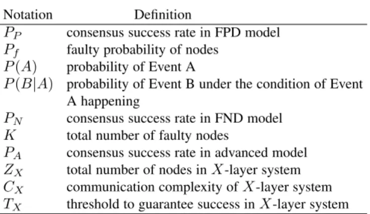
TABLE 1 Frequently used notations
Notation Definition
PP consensus success rate in FPD model
Pf faulty probability of nodes
P(A) probability of Event A
P(B|A) probability of Event B under the condition of Event
A happening
PN consensus success rate in FND model
K total number of faulty nodes
PA consensus success rate in advanced model
ZX total number of nodes inX-layer system
CX communication complexity ofX-layer system
TX threshold to guarantee success inX-layer system
4.1.1 Faulty probability determined
Let’s assumePfis the faulty probability of each node. To find
out the relationship between the success ratePP andPf, we shall
first define two important conditions, under which consensus can be reached.
• no more thanbm3cfaulty nodes in the first layer (EVENT
A)
• no more thanbm2cgroups fail in the second layer (EVENT
B)
In addition, Event A and Event B are not independent. If one replica in the first layer is faulty, it will be impossible for the corresponding sub-group to reach consensus. Therefore, we have
PP =P(A)⇥P(B|A). Assume that there are ifaulty nodes in
the first layer and 0 i bm3c. According to the cumulative
distribution function [31], we can get
P(A) =Xb m 3c i=0C i m(1 Pf)(m i)Pfi. (4)
The value ofP(B|A)depends on the value ofP(A). Equation (4) indicates there are alreadyi faulty nodes in the first layer. It
means i out of m groups in the second layer share no chance
to reach consensus as they have a faulty leader. Therefore, there
can be at mostbm
2cfailed groups in the second layer. We assume
there arejgroups, which do not have a faulty leader, fail to reach
consensus.0j bm 2c i. We have P(B|A) = bm 2c i X j=0 Pgj(1 Pg)(m i j). (5)
Pgrepresents the probability of a group, with a non-faulty leader,
failing to reach consensus. We assume there aregfaulty nodes in
one single group. To make this group fail,bn
3c+ 1gnsince
PBFT group tolerates up tobn
3cfaulty nodes. Therefore, we have
Pg = Xn g=bn 3c+1 CngP g f(1 Pf)n g. (6)
We can get the function of the system consensus success ratePP againstPf as follows PP = Xbm 3c i=0(C i m(1 Pf)(m i)Pfi bm 2c i X j=0 Pgj(1 Pg)(m i j)). (7)
To verify the closed-form expression derived, a simulation is performed based on random sampling in MATLAB. In the
simulation process, we take the faulty probability Pf and node
number m, n as the input and use a random array consisting
m+mnnumbers to represent the status of nodes. Each number
in this random array is either 1 or 0, representing faulty and non-faulty node respectively. On top of that, we set that each array element has a probability ofPf to be 1 (faulty), otherwise it is
0 (non-faulty). In this case, by counting the faulty nodes in each layer and sub-group and comparing the results with the thresholds, we can determine whether the consensus can be reached or not.
Then, the above mentioned process is repeated over10000times
and the simulation success rate for one value ofPfcan be obtained
by taking the ration of success times to the total repeating times.
Finally, by increasing Pf from 0 to 1, we can easily get the
simulation curve and compare it to the analytical result of the closed-form expression. The simulation design of the FND model is similar while the only difference is that FND takes the faulty node number instead of faulty probability as the input.
Note that, the purpose of the simulation is to examine the correctness of the derivations. Therefore, the complex peer-to-peer communication process is temporarily ignored in the simulation performed. However, we are also working on a system simulation, which takes every communication and view change into consider-ation, to further test the multi-layer PBFT system.
Fig. 4 shows clearly that the two curves match well, which verifies the effectiveness of the analytical result.
0.1 0.15 0.2 0.25 0.3 0.35 0.4 Probability of faulty nodes
0 0.1 0.2 0.3 0.4 0.5 0.6 0.7 0.8 0.9 1 Success rate Simulation Result Analytical Result
Fig. 4. Analytical and simulation results for success rate in FPD model.
(m=n= 30)
4.1.2 Faulty number determined
In the FND model, we assume that there areKfaulty nodes in
the whole system and aim to find the relationship betweenKand
the success ratePN. Meanwhile, we can use the same assumption
of event A and event B to calculatePN,PN =P(A)⇥P(B|A).
Unlike the FPD model, P(A) and P(B|A) are calculated
using the hypergeometric model [32] since the FND model is based on the prerequisite of a fixed number of faulty nodes. Thus, we have P(A) = 1 CK m+mn Xbm 3c i=0 C i mCmnK i. (8)
Also, there should be at most bm
2c i failed sub-groups with
non-faulty leaders, which means at mostbm
2c isub-groups have
more than bn
3c faulty nodes. However, in the FND model, the
number of faulty nodes in each group affects situations in the other groups so that it will be extremely complicated to consider
mgroups together. Therefore, a simplified binomial distribution
model on the group level is adopted, assuming every group has the same faulty probability ofPg2.
Pg2 represents the probability of a group with a non-faulty
leader failing in the second layer. It can be calculated as follows
P(B|A)⇡ bm 2c i X j=0 Pgj2(1 Pg2)(m i j), (9) Pg2= Xn g=bn 3c+1 Cg nC K g mn n 1 CK m+mn 1 . (10)
Then we can get the probabilityPN againstKas
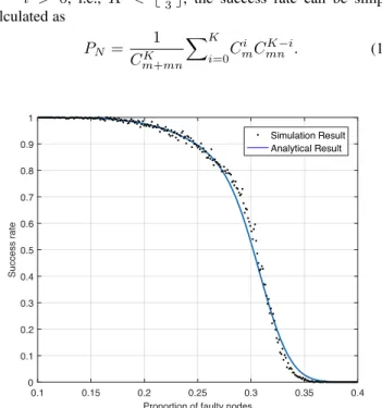
PN = 1 CK m+mn Xbm 3c i=0(C i mCmnK i X(bm 2c i) j=0 P j g2(1 Pg2)(m i j)). (11) In equation (11),Pbm3c
i=0Cmi CmnK i requiresK i >0since the
combinatorics of a combination number must be positive. When
K i > 0, i.e., K < bm
3c, the success rate can be simply
calculated as PN = 1 CK m+mn XK i=0C i mCmnK i. (12) 0.1 0.15 0.2 0.25 0.3 0.35 0.4
Proportion of faulty nodes 0 0.1 0.2 0.3 0.4 0.5 0.6 0.7 0.8 0.9 1 Success rate Simulation Result Analytical Result
Fig. 5. Analytical and simulation curves for success rate in the FND
model. (m=n= 30)
The curves in Fig. 5 show that, in the high success region where(PN >0.85), the analytical curve matches the simulation
curve. When the success rate of the system is lower, there is a slight difference between our calculation and simulation results. The rationale behind this is that a part of the model (group level
in the second layer) is simplified from hypergeometric distribution
to the binomial distribution by using Pg2 as a failure rate for
every group in equation (10). However, the error is negligible and will approach zero as the total number of the nodes in the system increases since the hypergeometric distribution approaches the binomial distribution in large systems [32].
4.2 Fault tolerance evaluation
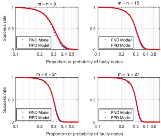
Comparing the FPD model and the FND model with different network sizes, Fig. 6 shows that the curves of the two models
gradually concur asmandnincrease.
0.1 0.2 0.3 0.4 0.5
Proportion or probability of faulty nodes 0 0.5 1 Success rate m = n = 9 FND Model FPD Model 0.1 0.2 0.3 0.4 0.5 0 0.5 1 m = n = 15 FND Model FPD Model 0.1 0.2 0.3 0.4 0.5
Proportion or probability of faulty nodes 0 0.5 1 Success rate m = n = 21 FND Model FPD Model 0.1 0.2 0.3 0.4 0.5 0 0.5 1 m = n = 27 FND Model FPD Model
Fig. 6. FPD and FND models’ analytical results with differentmandn.
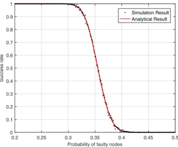
From Fig. 6, it can also be observed that asmandnget larger, the slope of the success rate curve approaches infinity aroundx=
1
3in both models. If we increasemandnto 500, the curve shows
a more obvious trend to step aroundPf = 13, as in Fig. 7. The
rationale behind this is that for a scaled-up system, faulty nodes are approximately evenly distributed. In this case, the proportion of faulty nodes in the whole system and that in each sub-group are very close. In other words, with the proportion of faulty nodes in
the whole system reaching around1
3, the corresponding proportion
within each consensus group also approximates 1
3, which is the security threshold in original single-layer PBFT. Therefore, the success rate steps to zero when the proportion of faulty nodes or the faulty probability exceeds1
3. Therefore, we have the following proposition.
Proposition 5. The system tolerates a larger proportion of faulty nodes when scaling up. The fault tolerance of two-layer PBFT converges to1
3 whenZgoes to infinite.
Fig. 6 only compares the situations where m and n are
multiples of 3. We choose these special circumstances because
when themandnare multiples of3, the system provides better
security performance compared with others. This can be explained by considering the threshold of faulty nodes within each group.
For example, two PBFT groups with 3f + 1and3f+ 3 nodes
can both toleratef faulty nodes at most based on the conclusion
in [11]. However, the ratio of maximum faulty nodes to the total nodes in the first group is bigger than that in the second one.
Therefore, assigningmandnto be multiple of three makes the
ratio reaches its maximum. Bringing these groups together, the whole system also shows better security performance. Moreover,
0 0.05 0.1 0.15 0.2 0.25 0.3 0.35 0.4
Probability of faulty nodes 0 0.1 0.2 0.3 0.4 0.5 0.6 0.7 0.8 0.9 1 Success rate m = n = 500
Fig. 7. Analytical result of FPD model withm=n= 500.
whenmis a multiple of6, the security performance is even better since we require at least half of the sub-groups to reach consensus.
This means two systems withm= 18andm= 19, for example,
both tolerate9failed sub-groups at most. In this way, systems with
an even integerm hold a larger ratio of faulty nodes. Based on
these, we have the following Remark.
Remark. By assigning m and n to be multiples of 6 and 3 respectively, the fault tolerance performance can be improved.
4.3 Advanced system and security optimization
In this subsection, the advanced system is proposed as an ideal and ultimate situation where the nodes in the two layers are classified. We assume that nodes in the first layer are always non-faulty, while nodes in the second layer have a probability of
Pf to be faulty. Note that, this is built under the assumption that,
by implementing view change whenever vulnerability is detected in the first layer, after a long period, the nodes left in the first layer are the ones with higher reliability. These nodes show more stable performance and remain faithful for a certain period of time. The consensus success rate of the advanced system can be calculated as PA= bm 2c X j=0 Pgj3(1 Pg3)(m j), (13) Pg3= Xn g=bn 3c+1 Cg nPfg(1 Pf)n g, (14)
wherePf represents the faulty probability of second-layer nodes
and PA represents the consensus success rate of the advanced
system. Comparing the analytical result with the simulation results in Fig. 8, we can see that the two curves concur. This proves the analytical result is valid.
In the practical systems, it is always worth to know what the
determined security threshold is, i.e., to achieve 100% success
rate, what is the maximum faulty nodes. Unlike the single-layer PBFT, the double-layer PBFT can be vulnerable if the faulty nodes are randomly distributed. This is because that the first layer is made up of one PBFT group consisting of a limited number of nodes, and the system has no chance to reach consensus if more than one-third of them are faulty nodes. In this case, as long as
0.2 0.25 0.3 0.35 0.4 0.45 0.5 Probability of faulty nodes
0 0.1 0.2 0.3 0.4 0.5 0.6 0.7 0.8 0.9 1 Success rate Simulation Result Analytical Result
Fig. 8. Analytical and simulation curves for success rate in advanced
system. (m=n= 30)
there are more bm
3c faulty nodes in the system, some specific
faulty node distributions will cause the system to fail. In other words, the first-layer nodes have more weights than the second for the final decision. However, as we mentioned in the introduction, this topology is very useful in decentralized systems to balance efficiency and security performance.
Fortunately, the determined security threshold can be improved over the operation time. In the advanced system where there is no faulty node in the first layer, the success rate stays at100%until the number of faulty nodes increases tobn
3c⇥b
m
2c. Note that the intermediate states exist but not presented. Therefore, we have the following proposition.
Proposition 6. To achieve100%success rate, the maximum num-ber of faulty nodes tolerated increases frombm
3ctob
n
3c⇥b
m
2cif the advanced system can be achieved.
However, this does not indicate that the consensus rate falls immediately to 0 when this threshold is exceeded. As shown in Fig. 8, the curve does not show a rapid decline until the probability
of faulty nodes reaches around0.3. To guarantees100%success
of consensus, number of faulty nodes can not be more than 1/6 of overall nodes. However, in practical deployments, especially with wireless communication uncertainty in large systems, it is very costly (and even impossible) to achieve a 100% success of consensus. Thus, fault tolerance of the double-layer system depends on the reliability requirement in different scenarios. For example, in 5G where the reliability requirement is lowered to 99.999% [33], the statistical fault tolerance is much higher than1 6 according to Fig. 8.
5
X
-LAYER PBFT SYSTEM
5.1 Communication complexity analysis of X-layer
system
X-layer PBFT system represents a general situation where
nodes in a network are allocated to more than 2 layers. The
consensus algorithm ofi-th (iX) layer is inserted between the
commit and reply phase ini 1-th layer so that communication
complexity can be further lowered. Suppose in anX-layer system,
where every layer is full, the number of nodes in each subgroup
in thei-th ofX-layer ismi+ 1(m0 = 1). The total number of nodesZX in thisX-layer system is
ZX= 1 + X X a=1 a Y i=1 mi ! . (15)
The communication complexityCXof thisX-layer PBFT system
is CX= X X i=1 mi 2mi 1(mi+ 1)2, (16) wherem 1is defined to be 1.
In this case, the minimum communication complexity of X
-layer system can also be transformed into a typical optimization problem, which aims to solve the minimum value of equation (16) under the restriction of equation (15). The method is similar to Proposition 9, which is omitted here. Fig. 9 compares the com-munication complexity of systems with the same number of nodes but different network depth. It shows that lower communication complexity can be obtained by dividing a system into more layers.
100 200 300 400 500 600 700 800 900 1000
Total number of nodes
102 103 104 105 106
Communication complexity four-layer PBFT
three-layer PBFT double-layer PBFT PBFT
Fig. 9. Communication complexity of PBFT and multi-layer systems. Therefore, we infer that the minimum communication
com-plexity CXmin will be reached if a system is divided into
maximum network depthXmax, i.e., by allocating the minimum
number of 3 replicas into every sub-group. In other words, the
Xth layer contains3X nodes in total. For givenZ,X
maxcan be
expressed as
Xmax=blog3(2Z+ 1)c 1. (17) To analyze the communication complexity of this limiting case,
we suppose thatZ is an integer that satisfiesZ = 1 + 3 + 32+
...+ 3Xmax. This is to say, there are exactly3 replicas in each
sub-group in each layer. In this case,CXmincan be calculated as
CXmin= XXmax i=1 3i 1(3 + 1)2 (18) = 16⇥1 3 Xmax 1 3 (19) =16Z 16 3 . (20)
So far, we have analyzed the communication complexity of multi-layer PBFT when the network depth is maximized. During this
process, we make an assumption about the number of replicas in each sub-group to explore the what the communication complexity
would approach when X continues to increase. The analytical
result shows the communication complexity of the Xmax-layer
system is lowered to 16Z 16
3 , a linear relationship with the node
numberZ. Therefore, we have the following proposition.
Proposition 7. The communication complexity is further lowered by increasing network depth and is in the range of1.9Z43 C
16Z 16
3 . In other words, multi-layer PBFT system provides better node scalability compared with the original PBFT.
However, It is worth mentioning that other performances such as security and latency serve as a trade-off when reducing the communication complexity. Detailed analysis is provide in Section 5.2 and Section 5.3 as follows.
5.2 Security analysis ofX-layer system
Like the double-layer system, the security performance of the
X-layer PBFT system can also be optimized over operation time
by a proper protocol. In this case, the threshold TX to maintain
the success rate at100%is
TX =b mX 3 c ⇥ b QX 1 i=1 mi 2 c. (21)
From equation (21), it can be seen thatTX < 16 and it drops
asX increases. In other words, by increasing the network depth,
the security performance is weakened while the communication complexity is improved. This is because increasing layer number leads to fewer node number in each layer, which makes the system more vulnerable to randomly distributed faulty nodes. In the practical scenarios, this trade-off should be considered when designing multi-layer PBFT systems.
5.3 Latency analysis
Another trade-off when reducing the communication complex-ity is latency, which will be analyzed in this subsection. In the proposed multi-layer PBFT, we construct a hierarchical structure to limit the peer-to-peer communication within each group or layer. Meanwhile, it is inevitable that the system confirmation delay is prolonged since the consensus reaching process is carried out in each layer successively.
In fact, the confirmation delay would keep increase with
increasing network depth X. Assuming that each layer takes
average tavg seconds to reach consensus and propagate to the
next layer, the average propagation delay tapd holds a linear
relationship with the network depth X, i.e., tapd = Xtavg.
Fortunately, if the protocol is used in the Internet, we can use parallel routes and distribute different information through differ-ent paths. In this way, though the consensus-reaching process still goes through different layers, the delay within groups is reduced, contributing to a lowered overall latency [34].
Conclusively, compared with original PBFT, the multi-layer PBFT sacrifices certain system delay while providing low com-plexity. Even though, compared with other consensus algorithms such as PoW that has good scalability, the latency of multi-layer PBFT is significantly lower. Therefore, the proposed system can be regarded as a trade-off between system delay and scalability of the existing protocols. Table 2 is provided to compare the perfor-mances of different protocols and the proposed multi-layer PBFT. As such, Considering the different demands of practical scenarios, different consensus protocols could be adopted to provide optimal performance accordingly.
6
THE PROTOCOLIn this section, we propose a practical protocol dedicated to the double-layer PBFT, where replicas in the first layer are denoted as
r1
i (superscript1for layer number, subscriptifor replica index).
r1
i act as leaders for corresponding second-layer replicas (r2i).
One leading r1
i and its corresponding r2is, all together, form a
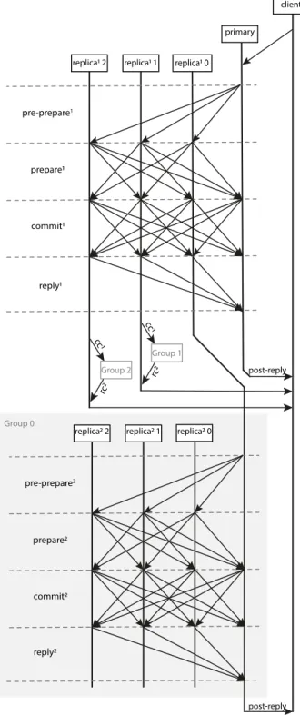
consensus group, resulting in a tree-like topology structure. When each group reaches consensus, group members reply to their leader instead of the client. Then the leader collects replies and sends it to the client on behalf of that consensus group. The client accepts the results only agreed by more than half consensus groups. The protocol overview is illustrated in Fig. 10. Meanwhile,
there is a group configuration GP that describes the allocation
group members and their leader. It will be updated when the network structure is changed. In brief, the new protocol inserts
successivepre prepare,prepare, andcommitphases before
starting thecommitphase in the upper layer.
6.1 Consensus flow
6.1.1 The client
A clientcsends a request message[o, t, c]request to primary.
This request invokes an operationowith timestampt. Timestamps
are ordered by time, so the stamp of later operation contains higher values. The request is sent to the replica. The identity of the replica is extracted from the view number contained in replies from previous operations. On receiving the request, primary multicasts messages using the protocol stated below.
All group leaders reply results to the client directly. The
poset reply has the form [o, t, c, i, r, rc1,⌫, GP]
poset reply
where ⌫ is the current view number, i is the replica number,r
is the result of the execution,rcis the reply certificate andGP
describes the replicas allocation.
Assuming there are a number of mreplicas in the first layer
and n in the second, and the number of faulty replicas in a
consensus group is fg (to distinguish from f). If leaders have
receivedfg+ 1matching valid replies from the same consensus
group, this group is said to have reached consensus. The network reaches consensus when more than half of the groups have the same replies. The client only accepts results replied from group leaders when at least half of them are consistent.
6.1.2 First-layer protocol
In the first layer, the primary andmreplicas form a consensus
group. When primarypreceives a request M = [o, t, c]request
from client, it authenticates the request and client’s identity.
Then primary assigns a sequence number ↵ to M. After that,
the primary steps into pre prepare phase by multicasting
[M, d,↵,⌫]pre prepare1 where d is the digest of M
(super-script is to distinguish pre prepare1 in the first layer from
pre prepare2in the second layer). Primary multicasts messages
only among r1. Thus, onlyr1 reacts on pre prepare1. The
propagation is restricted since the protocol runs layer by layer. Forpre prepare,prepareandcommitmessages, a replica
r1
i accepts the one with the same view ⌫; the authenticity is
then verified;↵is between watermarkhandH. The watermark
is introduced to ensure a weak synchronization and defined in Section 6.4.
With conditions above, a replica iin the first layer accepts a
pre prepare1message from primary only when there is none
different request with the same view⌫and sequence number↵is
accepted. Then it multicasts[d,↵, i,⌫]prepare1messages to allr1i
TABLE 2
Performance comparisons of the proposed and state of the art consensuses
Byzantine fault tolerance
Security Latency Communicationcomplexity Scalability
Original PBFT [11] Yes 1 3 Low O(Z 2) Low RAFT [8] No 1 2 Low O(Z) High Hotstuff [30] Yes 1 3 Medium O(Z) High Double-layer PBFT (proposed) Yes equation (7) equation (11) Medium 1.9Z 4 3 Medium Multi-layer PBFT
(proposed) Yes equation (21) High (Increases withnetwork depth)
1.9Z43 C 16Z 16
3 (decreases with network
depth)
High
messages to its log. During theprepare phase, eachr1i replica
collects2f messages with matching sequence number↵, view⌫,
and requestM. With the receivedpre prepare1messages, they
formprepared certif icate1, which indicates a particularr1
i
replica has prepared the request. For preparedr1
i, it multicasts[d,↵, i,⌫]commit1and waits for
more than 2f + 1 matching commit1 messages with the same
view, sequence and digest from different r1 replicas. Received
messages formcommit certif icate1(cc1) and this request is
said to be committed on replicar1
i. Then the replica pauses the
execution and initiates another round of protocol in the second layer as described in Section 6.1.3.
The committed replicas send[o, t, i, r,⌫]reply1 to their group leader, i.e., the primary in the first layer. The primary confirms that this group has reached consensus by checking more than half
of group members reply consistent reply1 messages, including
itself. The group leader collects reply1 and forms a
reply-certificate rc1. After that, this primary replies to the client with [o, t, c, i, r, rc1,⌫, GP]
poset reply. Notice that it is not necessary
for primary to reply to the client on behalf of consensus, but we require primary to do so to keep the algorithm the same on all replicas in case a massive deployment.
6.1.3 Second-layer protocol
A committedr1
i multicasts newpre preparemessage tor2
within the same consensus group, where another round of PBFT protocol is implemented. All group members reply to the leader in a similar manner in Section 6.1.2 when the request is committed again. For a replicar1
pwhich acts as primary, it multicasts a similar
[M, d,↵,⌫, cc1]
pre prepare2 to ri2 replicas in same consensus group, wherecc1is thecommit certif icate1. The⌫,↵, andM are inherited from the previous process. A replicar2
i in consensus
group will accept the request if the condition mentioned in the first-layer protocol is satisfied, in addition to the presence ofcc1.
On receiving validpre prepare2message, the pre-prepared
r2
i multicasts [d,↵, i,⌫]prepare2 messages to all ri2 in same
consensus group. It adds both pre prepare2 and prepare2
messages to its log. In the prepare2 phase, each r2 replica
collects 2f messages with matching sequence number ↵, view
⌫, and request M. With received pre prepare2 message, it
forms a quorum preparedcertif icate2, which indicates that this
r2
i replica has prepared the request.
Then the prepared replicas r2
i and their r1i leader multicast
[d,↵, i,⌫]commit2 and collect2f + 1 matchingcommit2
mes-sages with the same view, sequence and digest form differentr2
i
replicas. Thesecommit2formcommit certif icate2, and this
request is said to be committed. Replica then executes the message which has been committed. After the execution, all group members reply to the result to their group leader, and the leader replies to the client in a similar manner in Section 6.1.2. The pseudocode for protocol are described in algorithms 1, 2 and 3.
Algorithm 1Primary Normal-case Pseudocode
whilevalidrequest1received=Truedo ifclient identity authenticated=Truethen
m n.
multicastspre prepare1tor1.
end if end while
whilevalidprepare1received=Truedo
ifnumber of validprepare1>2f then
formsprepared certif icate1.
multicastscommit1tor1.
end if end while
whilevalidcommit1received=Truedo
ifnumber of validcommit1>2f then
formscommit certif icate1.
end if end while
whilevalidreply1received=Truedo
ifnumber of validreply1>half of membersthen formsrc1.
reply client withpost reply1.
end if end while
6.2 Faulty primary elimination
6.2.1 Faulty primary detection
The most commonly applied condition for initiating a view-change is by detecting whether the primary is responding, i.e., the replicas keep a timer which will be reset each time a new request is received. However, a faulty primary that assigns different
pre prepareto different replicas will not trigger time-out. Thus, we present a possible mechanism without a timer to detect faulty
primary nodes that multicast random messages during prepare
Algorithm 2r1
i Normal-case Pseudocode
whilevalidpre prepare1received=Truedo multicastsprepare1top r1.
end while
whilevalidprepare1received=Truedo
ifnumber of validprepare1>2f then
formsprepared certif icate1.
multicastscommit1tor1.
end if end while
whilevalidcommit1received=Truedo
ifnumber of validcommit1>2f then
formscommit certif icate1.
multicastspre prepare2to subordinater2.
end if end while
whilevalidprepare2received=Truedo
ifnumber of validprepare2>2f then
formsprepared certif icate2.
multicastscommit2tor2.
end if end while
whilevalidcommit2received=Truedo
ifnumber of validcommit2>2f then
formscommit certif icate2.
reply primary withreply1.
end if end while
whilevalidreply2received=Truedo
ifnumber of validreply2>half of membersthen formsrc2.
reply client withpost reply2.
end if end while
Algorithm 3r2
i Normal-case Pseudocode
whilevalidpre prepare2received=Truedo
multicastsprepare2tor1r2in same consensus group.
end while
whilevalidprepare2received=Truedo
ifnumber of validprepare2>2f then
formsprepared certif icate2.
multicastscommit2tor2in same consensus group.
end if end while
whilevalidcommit2received=Truedo
ifnumber of validcommit2>2f then
Forms a quorumcommit certif icate2.
Sendreply2to group leader.
end if end while pre-prepare1 prepare1 commit1 primary replica1 0 replica1 1 replica1 2 pre-prepare2 prepare2 commit2 replica2 0 replica2 1 replica2 2 Group 0 Group 2 cc 1 Group 1 cc 1 rc2 rc2 client post-reply reply1 reply2 post-reply
Fig. 10. Implementation flow chart for double-layer PBFT model. connection is lost, we want the detection to be independent without the prerequisite of total order and continuous sequence number↵, i.e., replicas accept discrete↵as long as it is consistently increas-ing/decreasing. To facilitate understanding of the mechanism, we first assume that the primary is not faulty. Since there are at most
f faulty replicas, the collected2f+ 1messages containf faulty
messages in the worst situation. And the restf+ 1messages must
be obtained from non-faulty replicas; thus, thosef+ 1messages
are identical. Those faulty messages (or the digest of the messages) could be unmatched with each other. Or, the faulty messages are identical, but those faulty messages are different from those
matching messages among non-faulty nodes. For simplicity, we say that in the latter case, there are two versions of messages
in 2f + 1 collections, one kept among non-faulty replicas, and
another version is kept among faulty replicas.
When primary is non-faulty and each replica collects2f+ 1
messages, the number of different versionsnvfalls in the interval
2andf + 1. That is because, in the worst case mentioned above,
each faulty replica multicasts different versions of messages,
resulting inf different versions among faulty replicas. Besides,
there is an additional version kept byf+ 1non-faulty replicas. At the presence of faulty primary that multicasts random messages,
the messages inpre preparethat received by non-faulty replicas
differ. In other words,nvexceeds the upper boundf+ 1, and the
primary is detected to be faulty. This condition, along with time
out, triggers theview changephase.
6.2.2 View change
In conventional PBFT [11], replicas invoke view change in prepare phase. Changes are made to adapt to our multi-layer model. As shown in Fig. 1, a replica is the primary of its sub-layer replicas. Thus, in this protocol, replicas in a specific sub-layer detect their faulty primary in the upper layer and invoke cross-layer view change. Each replica, which suspects the primary to
be faulty, multicasts aview changemessages with the stable
checkpoint to new primary (the new primary may be determined by election mechanism based on current view number). The new
primary decides whether to lunchnew view.
Suppose a replica is in layer L as a member for group K,
and notice the group leader is the group member of group in
layer L 1. If it suspects the group leader is faulty for not
responding or deliver pre prepare messages with invalid
sequence number, it stops accepting requests and starts view
change that moves the view of this group from ⌫ into ⌫ + 1
by multicasting [⌫ + 1,↵, C, P, i]view change, where ↵ is the
sequence number for the latest checkpoint for this replica and
C is the 2f matching certificate for this checkpoint. P is the
collection ofprepare certif icate(2f + 1matching prepare
requests) for eachpre preparerequest that higher than↵.iis
the identification of the sender.
If the new primarypin new view⌫+ 1has received2f 1
valid view change messages from other group members. It
multicasts [⌫ + 1, GP, , O]new view, where the is a set of
2f matchingviewChange certif icates, andOis the set of
pre prepare messages than need to be multicasted for they
are failed to reach consensus in last view ⌫. The sequence of
pre prepareinOis ranging from the latest checkpoint know to the new leader and the latest↵inP.GP is the update of itself.
describes howpallocate its group member in layerL 1to the
rest members in group K. Member replicas accept and execute
a valid new view. Those mentioned above are similar to original view-change protocol.
However, taking over the leader of group K in layer L
implies that this replica becomes the member of a group in layer
L 1 (for instance, group J). Thus, the primary p multicasts
[join,⌫, , i]join to group J after the view change. The ⌫
is view number for group J since it should remain unchanged
if there is no view change in J.pextracts view in J from the
commit certif icatethat passed by the original group leader
from groupK. Matching ⌫ and prove the validity. Then this
replica directly commits the current operation since it must have
been committed in layerL 1, otherwise the consensus protocol
will not be executed in layer L. Thisjoin message informs the
member in groupJ that there is a change of replica and groupJ
update localGP.
Also, a member in layer L is the leader in layerL+ 1. To
reallocate its former members (sincepis no longer their leader), it multicasts[v+1, G, , i, r]redistributeto replicarwhereGis the
new designated group in layerL 1for replicar. The replicar
then redirects itself to groupGand update localGP. The replicas
governed by groupK in layer deeper than L 1 are reaching
consensus in seam sequence since they are (indirectly) lead by groupK. The effect of view change is limited.
To reduce the extra communication complexity and latency
introduced by this modified protocol, theredistributemessages
are embedded into GP in new view message. Then it is
extracted by current members of groupKand pass to their former
group in layerL+ 1by piggybacking inpre prepare. Those
replicas in layerL+ 1redirect themselves before responding to
new pre prepare. Thus, only the join message attributes to extra communication expenditure which, in the two layer case, the sizemof layer1.
To facilitate the assessment of view change complexity of our double-layer scenario, suppose that the number of replicas in the first layer ism, and for each group in the second layer isn(as depicted in Fig. 1). Note that the view change can be triggered from either the first layer or the second layer. First, we consider the case that the view change is triggered in the first layer. As described in the protocol, the first part of our view change process runs within this layer (which is similar to original PBFT). For this part, the complexity isO(m3). As one of the members in the first layer is selected as the new primary, the extra complexity is
introduced by multicasting theredistributemessages to its group
in the second layer. Since the certificate is generated in the first layer, the complexity of this part isO(m2n). The total complexity isO(m3+m2n).
Then we consider that a view change is triggered in one of the groups in the second layer. Similarly, the complexity isO(n3)for the first part. The extra complexity is introduced by multicasting thejoinmessages to the first layer. However, the certificate is now generated in one of the groups in the second layer. For this reason, the additional complexity isO(n2m). Then the total complexity isO(n3+n2m).
For comparison, the complexities areO((m+mn)3)for the
original PBFT andO(m+mn)for HotStuff when considering
the same total number of replicas. It can be seen that in both first layer or second layer triggered cases, the complexity of proposed double layer PBFT is not as good as HotStuff, however, it reduces the complexity in large scale when compared with original PBFT.
6.3 Operation synchronization
The precondition for entering the next phase does not require synchronization across all replicas. Due to the loss of connection or other reasons, one replica may skip some operations. Though
the consensus is still reached, the sequence number ↵ is not
necessarily continuous.
But for clients who also access data from the network, oper-ations are preferably synced on each replica. The asynchronous replica can be detected by the discrete sequence number and the reached watermark. A replica may extract the missing operations by inquiring them from other replicas in real-time or at a constant interval.
Once the replica decides to extract a missing operation from the rest of the network, it multicasts [n↵, i,⌫]extract request.
If there are no fewer than 2f + 1 valid extract reply, the