METHODOLOGIES FOR THE WEIGHT
ESTIMATION OF AIRCRAFT STRUCTURES
by
Christine Hannon
Submitted in accordance with the requirements for the degree of
Doctor of Philosophy
The University of Leeds School of Mechanical Engineering
August 2011
The candidate confirms that the work submitted is his own and that appropriate credit has been given where reference has been made to the work of others. This copy has been supplied on the understanding that it is copyright material and that no quotation
Some parts of the work presented in this thesis have been published in the following articles. In each case, details of the contributions by myself and other authors are detailed, as well as which chapters the contents of the articles feature in:
Hannon, C., Agyepong, L., Toropov, V.V., and Querin, O.M, "An Al-ternative View on Weight Estimation for the Aircraft Industry: Problems and MDO Solutions", Proceedings of the 12th AIAA/ISSMO Multidisciplinary Analysis and Op-timization Conference, September 10 - 12, 2008, Victoria, British Columbia, Paper number: AIAA-2008-5877.
My contributions: The work in this paper is all my own.
Contributions from other authors: Prof. Toropov and Dr. Querin provided super-vision, feedback and general guidance. Lucy Agyepong contributed with information and data pertaining to system design within the fixed trailing edge.
Chapters based on this work: Part of the theory about ANFIS appears in the definition of the methodologies used in Chapter 3. The case study and results are part of Chapter 4.
Hannon, C., Toropov, V.V., and Querin, O.M,"A Neuro-Fuzzy Approach to the Weight Estimation of Aircraft Structures.", Proceedings of the 2nd RAeS/CEAS Aircraft Structural Design Conference, Royal Aeronautical Society, 26-28 October 2010, London, UK.
My contributions: The work in this paper is all my own.
Contributions from other authors: Prof. Toropov and Dr. Querin provided supervision, feedback and general guidance.
Chapters based on this work: Part of the theory about NEFPROX appears in the definition of the methodologies used in Chapter 3. The case study and results are part of Chapter 6.
Hannon, C., Toropov, V.V., and Querin, O.M, A Neuro-Fuzzy Approach to the Weight Estimation of Aircraft Structural Components" , Accepted for publication in the Aeronautical Journal.
supervision, feedback and general guidance.
Chapters based on this work: Part of the theory about NEFPROX appears in the definition of the methodologies used in Chapter 3. The case study and results are part of Chapter 6.
The problem of weight estimation in the aerospace industry has been acquiring considerably greater importance in recent years, due to the numerous challenges fre-quently encountered in the preliminary phases of the design of a new aircraft. This is the stage where it is possible to make design changes without incurring into excessive cost penalties. On the other hand, the knowledge of the design, of the relationships existing between the different variables and their subsequent impact on the final weight of the structure is very limited. As a result, the designer is unable to understand the true effect that individual design decisions will produce on the weight of the structure. In addition to this, new aircraft concepts end up being too conservative, due to the high dependency of current weight estimation methods to historical data and off-the-shelf design solutions.
This thesis aims at providing an alternative framework for the weight estimation of aircraft structures at preliminary design stages. By conducting a thorough assess-ment of current state-of-the-art approaches and tools used in the field, fuzzy logic is presented as an appropriate foundation on which to build an innovative approach to the problem. Different adaptive fuzzy approaches have been used in the development of a methodology which is able to combine an analytical base to the structural design of selected trailing edge components, with substantial knowledge acquisition capabili-ties for the computation of robust and reliable weight estimates. The final framework allows considerable flexibility in the level of detail of the estimate consistent with the granularity of the input data used. This, combined with an extensive uncertainty analysis through the use of Interval Type-2 fuzzy logic, will provide the designer with the capabilities to understand the impact of error propagation within the model and increase the confidence in the final estimate.
little hope for advance" -Orville
Before starting my PhD, people warned me about the fact that it is a very solitary process. Although this is true at times, I never thought I would receive support, advice and, most importantly, friendship from as many people as I have had in the past few years.
First and foremost, I would like to thank Dr. Osvaldo Querin and Prof. Vassili Toropov from the bottom of my heart for guiding me through the maze and for always believing in me. Your advice and guidance was invaluable, especially when times got hard. Thank you so much for sharing your knowledge and your time with me. A special thanks goes to Prof. John Doherty and Dr. John Harris. I would not have had this opportunity if it had not been for them.
I would also like to thank the Mass Properties team at Airbus UK for allowing me to work with them and for giving me precious insight in the work of a weight engineer. In particular, I would like to give a special thanks to Evangelos Vekris, Paul Asbury, Robby and Ed for making my secondment in Filton a very enjoyable time.
I could never have done it without Lucy Agyepong. We shared every single moment of this process together and I would have lost my sanity if I had not had her on my side. Thank you, my dear sister.
I certainly would not have been the happy person I am today without the people in G54b keeping my spirits up all this time. A massive thank you especially to Franz, Andy, Justin, Carwyn, Pete and Andrew for always putting a smile on my face and reminding me that sometimes things are not as hard as they seem. And to Nisha and Neil, the honorary members of the G54b crowd. An extra special mention goes to Dave Readman and everybody in the lab for their endless assistance.
To my mum and dad and the rest of my family, for helping me through this journey in more ways than I ever thought possible. And to my sister Clare for not killing me every single time I went out of my mind. You are the best sister in the world. To Patrick, my best friend and true love, for always giving me the strength to go on. And to God, who is always there by my side.
1 Introduction 1 1.1 The challenges for weight estimation in the aircraft industry. 2
1.2 Scope and objectives of this research 6
1.3 Thesis layout . . . 7
2 Weight Estimation for Aircraft Structures: Theory and Practice 11
2.1 Introduction... 12
2.2 Classification of current approaches. 12
2.3 Empirical weight estimation . . . 15
2.3.1 Derivation of empirical formulations 15
2.3.2 Level of granularity of empirical weight estimation methods 17
2.3.3 Benefits and limitations . . 24
2.4 Semi-analytical weight estimation . 27
2.4.1 Applicability of semi-analytical weight estimation formulations 30
2.5 Analytical methods. 31
2.6 Alternative solutions 38
2.6.1 Solid modelling and Finite Element Analysis for weight estimation 38 2.6.2 Functional level weight estimation methodologies . . 45 2.7 Weight optimisation and management in the design process 49 2.8 Summary . . . .' . . . 53
3 An Alternative Approach to Weight Estimation 3.1 Introduction . . . .
3.2 A new perspective on weight estimation
3.3 Fuzzy logic for knowledge acquisition and management.
55 56 56 59
3.3.2 Reasoning with fuzzy logic 61
3.4 Neura-fuzzy systems . . . 65
3.4.1 Adaptive Network-based Fuzzy Inference Systems (ANFIS) 66 3.4.2 Neura-Fuzzy Approximator (NEFPROX)
3.5 Designing under uncertainty . . . 3.5.1 Interval type-2 fuzzy sets
3.5.2 Type-2 fuzzy systems and their structure 3.6 Summary . . . .
4 ANFIS for Weight Estimation Problems 4.1 Introduction . . . .
4.2 Weight estimation for aircraft secondary structures 4.2.1 Case study: spoiler attachment ribs
4.3 Model development . . . .
4.3.1 Subtractive clustering for fuzzy model extraction 4.3.2 Variable selection . . . . 4.3.3 Parameterisation and data pre-processing 4.4 R e s u l t s . . .
4.4.1 Sensitivity and model selection 4.4.2 Model performance .
4.5 Summary . . . .
5 Integration of Network-based Weight Estimation in the Design Pro-cess
5.1 Introduction.
5.2 Structural design with fuzzy logic . 5.2.1 Model framework . . . .
5.3 ANFIS-based structural sizing and weight analysis: spoiler attachment ribs.
5.3.1 5.3.2 5.3.3
Loading and structural sizing Sizing module performance . Weight module performance .
70 71 73 75 76 78 79 79 80 83 83 85 87 90 90 92 96 99 100 101 102 104 105 107 109
ribs. 5.4.1 5.4.2
Sizing module performance Weight module performance .
112 116 117 5.5 The TSK fuzzy knowledge base: structure, interpretability and versatility121 5.6 Summary . . . 124
6 Fuzzy Systems and Their Interpretability for Design Applications 130 6.1 I n t r o d u c t i o n . . . 131 6.2 Selecting a fuzzy system for design applications: accuracy vs.
inter-pretability . . . 132
6.2.1 Interpretability of fuzzy systems 133
6.3 NEFPROX-based structural sizing and weight estimation: spoiler at-tachment ribs . . . 134
6.3.1 Sizing module performance 137
6.3.2 Weight module performance . 138
6.4 NEFPROX-based structural sizing and weight estimation: aileron at-tachment ribs . . . 142
6.4.1 Sizing module performance 144
6.4.2 Weight module performance. 146
6.5 Mamdani vs. Sugeno for knowledge acquisition in the design process 151 6.6 Summary . . . .. 155
7 Type-2 Fuzzy Logic for Uncertainty Management and Propagation in
Weight Estimation 161
7.1 I n t r o d u c t i o n . . . 162 7.2 Type-2 fuzzy systems theory for scenario analysis. 163 7.2.1 Development and optimisation of interval type-2 fuzzy logic systems166 7.2.2 The iterative design approach.
7.2.3 SVD-QR routine . . . .
7.3 Structural sizing and weight analysis using interval type-2 fuzzy systems: spoiler attachment ribs . . . .
7.3.1 Sizing module performance
167 168
171 173
7.3.3 Interval type-2 function approximation and decision boundaries. 178 7.4 Structural sizing and weight analysis using interval type-2 fuzzy systems:
aileron attachment ribs. . . 181
7.4.1 Sizing module performance 181
7.4.2 Weight module performance. 184
7.4.3 Interval type-2 function approximation and decision boundaries . 186
7.5 The uncertain rulebase . 190
7.6 Summary . . . . . . 198
8 Integration of Knowledge and Uncertainty in the Design Process 208 8.1 I n t r o d u c t i o n . . . 209 8.2 Fuzzy systems for weight estimation applications 210 8.2.1 Granularity and interpretability in adaptive fuzzy systems. 210 8.2.2 The problem of preservation of information . . . 213 8.3 Towards a general fuzzy logic-based framework for weight estimation 215
8.3.1 Integration in the design process 216
8.4 Summary . . . 219
9 Conclusion 222
9.1 Achievements and contributions. 223
9.2 Conclusions... 9.3 Recommendations for future work
References
226 227
1.1 Aircraft empty weight breakdown. . . . . . 1.2 Influence of weight on range for propeller driven aircraft .. 1.3 Thesis layout . . . .
3 4 9
2.1 Aircraft design process. . . . 13 2.2 Variation in weight due to passenger capacity for commercial transports. 19 2.3 Graphical interpretation of the growth factor. . 23
2.4 Commercial transport MTOW per seat trend. . 25
2.5 Semi-analytical wing weight build-up methodology. 28 2.6 Typical sheet-stringer-rib type wing structure.. . . 33 2.7 Variation in F-18 wing weight according to material selection. 36
2.8 Spar geometry distribution. 37
2.9 Skin thickness distribution. 38
2.10 Development and validation of mass factors for FEM conversion. 40 2.11 Categorisation of subfactors.. . . 41 2.12 Theoretical weight as a function of actual as built weight. 42 2.13 Structural weight estimation in CONSIZE.. . . 43 2.14 Increase in confidence with learning through weight probability
distri-butions. . . 46 2.15 Evolutionary approach to structural weight estimation in Airbus. 47 2.16 Funnel of weight and cost. . . 49 2.17 Rib topology with and without the effect of pattern repetition for system
routing . . . .
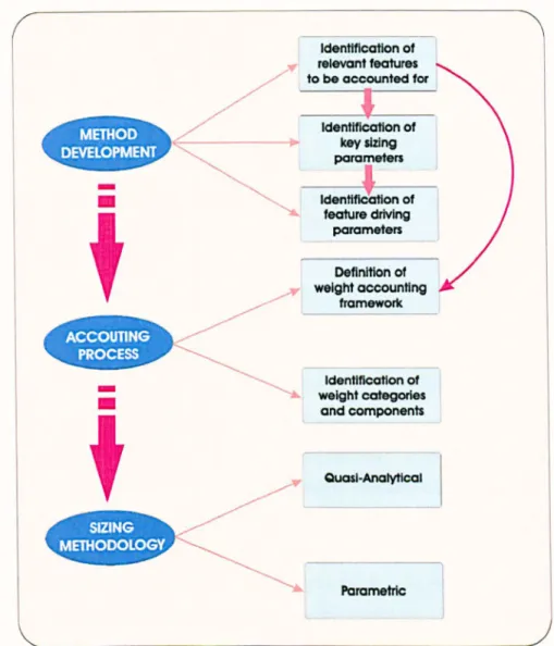
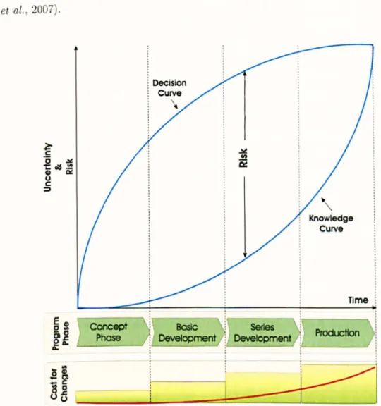
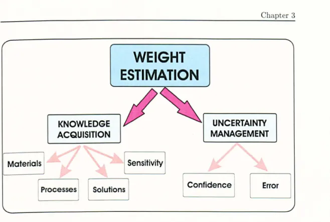
3.1 Evolution of risk and cost during the aircraft design process. 3.2 Decomposition of the weight estimation problem . . . .
53
57 59
3.4 Definition of the design space though membership functions and fuzzy rules . . . .
3.5 Evolution of fuzzy rules in the design process.
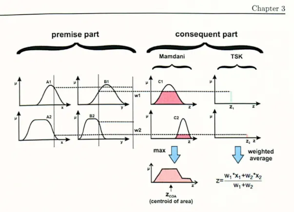
61 62 3.6 Fuzzy inference system. . . . 63 3.7 Differences in output derivation between Mamdani and TSK FIS. . 64
3.8 ANFIS network. . 67
3.9 MANFIS network. 69
3.10 Structure of the NEFPROX network. . 70
3.11 Uncertainties in the design process. . . 71
3.12 Visual representation of the transition from type-1 to interval type-2 fuzzy set. . . . 74 3.13 Footprints of uncertainty for type-2 membership functions. 75 3.14 Type-2 fuzzy inference system. . . . . . 75
4.1 A general midboard fixed trailing edge assembly. 81
4.2 Idealisation of a spoiler attachment rib. 83
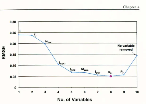
4.3 Variable selection process. . . 86 4.4 Effect of variable removal on the accuracy of model A for spoiler
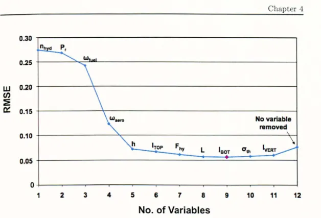
attach-ment ribs. . . .. 91 4.5 Effect of variable removal on the accuracy of model for spoiler
attach-ment ribs. . . 92
4.6 ANFIS model performance on testing data. 93
4.7 Effect of height and length on the weight of spoiler attachment ribs. 94 4.8 Effect of height and hinge load on the weight of spoiler attachment ribs. 95 4.9 Effect of aerodynamic and hinge loads on the weight of spoiler
attach-ment ribs. . . .. 95 4.10 Effect of hinge and hydraulic system attachment loads on the weight of
spoiler attachment ribs. . . .. 96
5.1 Flow of information for the weight estimation of structural components. 102 5.2 Illustrative framework architecture for neuro-fuzzy sizing and weight
ment ribs . . . 105 5.4 Idealisation of a spoiler attachment rib for ANFIS sizing and weight
estimation. . . . 106 5.5 Performance of the MANFIS sizing module for spoiler attachment ribs
on testing database for cross sectional area and second moment of area. 108 5.6 Effect of axial and bending loads on beam sizing for spoiler attachment
ribs. . . . . 109 5.7 Effect of variable removal on the accuracy of the ANFIS weight module
for spoiler attachment ribs. . . . . 110 5.8 Performance of the ANFIS weight module for spoiler attachment ribs on
testing database. . . 111 5.9 Variation in spoiler attachment rib weight with respect to hinge line
datum and spar height for hinge ribs and intermediate ribs . . . 112 5.10 Effect of local geometry on rib structural weight for spoiler hinge ribs
and intermediate ribs. . . . . 112 5.11 Idealisation of Design A for the aileron attachment ribs for ANFIS sizing
and weight estimation . . . 113 5.12 Idealisation of Design B for the aileron attachment ribs for ANFIS sizing
and weight estimation. . . 113 5.13 Idealisation of Design C for the aileron attachment ribs for ANFIS sizing
and weight estimation . . . 114 5.14 Three-level sizing and weight estimation framework for aileron
attach-ment ribs . . . 115 5.15 Performance of the MANFIS sizing module for aileron attachment ribs
on testing database for A and I. . . . . 117 5.16 Effect of axial and bending loads on beam sizing for aileron support ribs. 118 5.17 Effect of variable removal on the accuracy of the ANFIS weight module
for aileron attachment ribs. . . . . 119 5.18 Performance of the ANFIS weight module for the aileron attachment
the structural weight of aileron attachment ribs. 121 5.20 Effect of cross sectional areas of top and bottom beam section on the
structural weight of aileron attachment ribs. . . 122 5.21 Variation in the aileron attachment rib weight due to the presence of
back and front vertical beam sections. . . . . 122 5.22 Effect of hinge line datum and top beam cross sectional area on the
structural weight of aileron attachment ribs . . . 123 5.23 Rulebase for the estimation of sectional properties for spoiler attachment
ribs. . . . . 126 5.24 Rulebase for the estimation of structural weight of spoiler attachment
ribs. . . . . 127 5.25 Rulebase for the estimation of sectional properties for aileron attachment
ribs. . . . . 128 5.26 Rulebase for the estimation of structural weight of aileron attachment
ribs . . . 129
6.1 Three-level NEFPROX-based sizing and weight estimation framework for the spoiler attachment ribs. . . 135 6.2 Performance of the NEFPROX sizing module for spoiler attachment ribs
on testing database for A and 1. . . . 137 6.3 Effect of axial and bending loads on beam sizing for spoiler attachment
ribs. . . . . 139 6.4 Performance of the NEFPROX weight module for spoiler attachment
ribs on testing database. . . 140 6.5 Effect of variable removal on the accuracy of the NEFPROX weight
module for spoiler attachment ribs . . . 141 6.6 Variation in spoiler attachment rib weight with respect to the hinge line
datum and spar height for hinge ribs and intermediate ribs, as derived through the NEFPROX weight module. . . 142 6.7 Effect of local geometry on the rib structural weight for spoiler hinge
ribs and intermediate ribs, as derived through the NEFPROX weight module . . . 142
for the aileron attachment ribs. . . . . 143 6.9 Performance of the NEFPROX sizing module for aileron attachment ribs
on testing database for A and 1. . . . 145 6.10 Effect of axial and bending loads on beam sizing for aileron attachment
ribs. . . . . 146 6.11 Performance of the NEFPROX weight module for aileron attachment
ribs on testing database . . . 147 6.12 Effect of variable removal on the accuracy of the NEFPROX weight
module for aileron attachment ribs . . . 148 6.13 Variation in the aileron attachment rib weight with respect to changes
in the hinge line datum and spar height, as derived by the NEFPROX model. . . . 149 6.14 Variation in the aileron attachment rib weight with respect to changes
in the cross-sectional areas of top and bottom beam sections, as derived by the NEFPROX model. . . 150 6.15 Variation in the aileron attachment rib weight due to the presence of
back and front vertical beam sections, as derived by the NEFPROX model. . . . 150 6.16 Variation in the aileron attachment rib weight with respect to changes
in the hinge line datum and top beam cross-sectional area, as derived through NEFPROX . . . 151 6.17 Comparison between the membership functions for the individual
vari-ables in the weight module for spoiler attachment ribs, as derived using A~FIS and NEFPROX. . . 157 6.18 Comparison between the membership functions for the individual
vari-ables in the weight module for aileron attachment ribs, as derived using ANFIS and NEFPROX. . . 158 6.19 Rulebase for the estimation of sectional properties for spoiler attachment
ribs, as derived with NEFPROX. . . 159 6.20 Rulebase for the estimation of sectional properties for aileron attachment
discrete values of x and u . . . 164 7.2 Performance of the type-2 fuzzy logic sizing module for spoiler
attach-ment ribs on testing database for A and 1. . . . 175 7.3 Performance of the type-2 fuzzy logic weight module for spoiler
attach-ment ribs on testing database. . . 176 7.4 Effect of variable removal on the accuracy of the type-2 fuzzy logic weight
module for spoiler attachment ribs . . . 177 7.5 Confidence boundaries in the estimation of spoiler attachment rib weight
depending on hinge line datum and spar height for hinge ribs and inter-mediate ribs. . . . 180 7.6 Confidence boundaries in the estimation of spoiler attachment rib weight
depending on the cross sectional areas of top and vertical beam sections for hinge ribs (a) and intermediate ribs (b) . . . 180 7.7 Performance of the type-2 fuzzy logic sizing module for aileron
attach-ment ribs on testing database for A and 1. . . . 183 7.8 Performance of the type-2 fuzzy logic weight module for aileron
attach-ment ribs on testing database. . . 185 7.9 Effect of variable removal on the accuracy of the type-2 fuzzy logic weight
module for aileron attachment ribs . . . 186 7.10 Confidence boundaries in the estimation of aileron attachment rib weight
depending on hinge line datum and spar height for hinge ribs and inter-mediate ribs. . . . 188 7.11 Confidence boundaries in the estimation of aileron attachment rib weight
depending on the cross sectional areas of top and bottom beam sections. 189 7.12 Confidence boundaries in the estimation of aileron attachment rib weight
depending on the presence of back and front vertical beam sections. . . 189 7.13 Confidence boundaries in the estimation of aileron attachment rib weight
depending on the location of hinge line datum and top beam cross sec-tional area. . . . . . . 190 7.14 Type-2 fuzzy partitions used to define bending moment, axial force, cross
the spoiler weight estimation module. 203 7.16 Type-2 fuzzy partitions used to define bending moment, axial force, cross
sectional area and second moment of area within the aileron sizing module.203 7.17 Type-2 fuzzy partitions used to define input and output variables within
the aileron weight estimation module. . . . . 206
8.1 Diagram showing the various levels of granularity achieved with the dif-ferent fuzzy systems. . . . . . 212 8.2 Diagram showing the process of knowledge extraction and amalgamation
for fuzzy systems . . . 214 8.3 Flowchart outlining the framework for the 3-level process for the weight
2.1 Identification of functional weight groups for the Fixed Fraction Method. 20
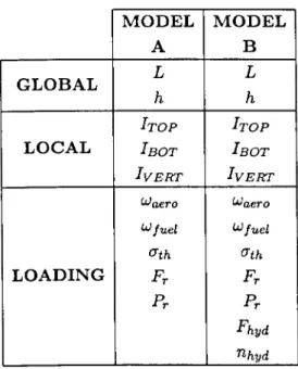
4.1 Input variables for ANFIS geometrical fuzzy model. . . . 89
5.1 Performance assessment of ANFIS framework applied to the sizing and weight estimation of spoiler attachment ribs. . . . . 108 5.2 Performance assessment of ANFIS framework applied to the sizing and
weight estimation of aileron attachment ribs. . . . . 116
6.1 Performance assessment of the NEFPROX framework applied to the sizing and weight estimation of spoiler attachment ribs. . . . 138 6.2 Performance assessment of NEFPROX framework applied to the sizing
and weight estimation of aileron attachment ribs . . . 144 6.3 Comparison of results for the architecture sizing and weight fuzzy
in-ference systems built with ANFIS and NEFPROX for both spoiler and aileron attachment ribs. . . 153
7.1 Comparison of results for the architecture of sizing and weight fuzzy inference systems of type-1 built with NEFPROX and interval type-2 for spoiler attachment ribs. . . . 174 7.2 Performance assessment of the interval type-2 fuzzy logic framework
applied to the sizing and weight estimation of spoiler attachment ribs. . 174 7.3 Comparison of results for the architecture of sizing and weight fuzzy
inference systems of type-1 built with NEFPROX and interval type-2 for aileron attachment ribs. . . 182 7.4 Performance assessment of the type-2 fuzzy logic framework applied to
output variables within the spoiler sizing module . . . 193 7.6 Uncertainty characteristics for the type-2 fuzzy partitions of input and
output variables within the spoiler weight module. . . . . 194 7.7 Uncertainty characteristics for the type-2 fuzzy partitions of input and
output variables within the aileron sizing module. . . . . . 196 7.8 Uncertainty characteristics for the type-2 fuzzy partitions of input and
Most of the symbols used in this thesis have different meanings in different chapters while others are only relevant to short sections of text. Below are listed those symbols which have a general meaning, however specific definitions will depend on the context.
A, a ABOT ATOP AVERT AVERTb AVERT! B, b C Cgf E h [BOT
Irop
[VERT Kca Krsv L L 75 m n N Constants of proportionalityCross sectional area for rib bottom beam section Cross sectional area for rib top beam section Cross sectional area for rib vertical beam section Cross sectional area for rib back vertical beam section Cross sectional area for rib front vertical beam section Constants of proportionality
Engine performance parameter Correlation factor
Young's modulus
Load from hydraulic system attachment Hinge load
Axial load Spar height
Second moment of area for rib bottom beam section Second moment of area for rib top beam section Second moment of area for rib vertical beam section
Correlation factor for extra fuel burnt in climb and acceleration Constant for reserve fuel
Coefficient relating aircraft variable weight to its gross weight Hinge line datum
Aircraft lift to drag ratio
Mean for primary membership function Maximum resultant bending moment Propeller cruise efficiency
Number of components
I{ Potential of numerical data point
P
r Strut loadR Aircraft design range r a Cluster radius
ra Radius of cluster with reduced potential
Ri
Fuzzy rulertype Type of support rib B Estimated standard error
BFC Aircraft average cruise specific fuel consumption TSFC Aircraft average cruise thrust specific fuel consumption w Fuzzy rule firing strength
W Normalised firing strength
W Weight
We Aircraft constant weight component Wfuel Fuel weight
Wg Aircraft gross weight Wo Aircraft fixed weight Wpl Payload weight
Wv Aircraft variable weight component Xi Input variable
Yi Output variable
Greek letters
J.L Shape of membership function Waero Aerodynamic load
Wfuel Fuel load
~ Fuzzy basis function a Standard deviation ath Applied thermal stress ault Ultimate tensile stress
{) Variable predicted value Abbreviations AAW ANFIS ANN ATM CAD CONSIZE DoE FE FEA FEM FEMMAS FIS FLOPS FLS FTE FOU FS GF IFTE IMPACT IT2 MANFIS MAPE MF MFTE
Active Aeroelastic Wing
Adaptive Network-based Fuzzy Inference System Artificial Neural Network
Advanced Technology Multiplier Computer Aided Design
CONfiguration SIZing Program Design of Experiments
Finite Element
Finite Element Analysis Finite Element Model
Finite Element Method for Mass Estimation Fuzzy Inference System
FLight OPtimisation System Fuzzy Logic System
Fixed Trailing Edge Footprint of Uncertainty Fuzzy Set
Growth Factor
Inboard Fixed Trailing Edge
Innovative Mass Properties Analysis CATIA Tool Interval Type-2 fuzzy system
Multiple Adaptive Network-based Fuzzy Inference System Mean Absolute Percentage Error
Membership Function
MTOW
NEFPROX
NOMF
OFTE
OWE
RBF
RMSE
SR
SSSP
SVD
TOS
TSK
WAATS
WER
WISE
YEIS
~aximum Take-Off Weight Neuro Fuzzy Approximator N on-Optimal ~ass Factor Outboard Fixed Trailing Edge Operational Wight Empty Probability Density Function Radial Basis Function Root ~ean Square Error Specimen Rib
Space Shuttle Synthesis Program Singular-Value Decomposition Theoretical Optimal Structure Takagi-Sugeno-Kang fuzzy system
Weight Analysis of Advanced Transportation Systems Weight Estimating Relationships
Weight Integrated Sizing Evaluation Year of Entry Into Service
Introduction
Contents
1.1 The challenges for weight estimation in the aircraft industry 2 1.2 Scope and objectives of this research • . • . . . • • 6 1.3 Thesis layout . . . • • • . . . . . 7
1.1 The challenges for weight estimation in the aircraft
industry
The success of a new aircraft program is directly proportional to the ability of the new design to satisfy the operational needs and requirements set by the customers. In addition to being reliable and technically robust, the aircraft needs to be able to justify its selling price and operating costs by providing the performance levels stipulated with the customer. The preliminary stage of the design of a new aircraft, in particular, is the most critical point for the attainment of the required commercial competitiveness. It is at this time that the design team determines whether the agreed operational capabilities are technically feasible and defines the best combination between performance and cost within the limits of available technology and constraints.
Weight control, namely the process by which the lightest possible airplane is derived within the constraints of the design criteria (Niu, 1988), is an essential module of the design process of any aerospace vehicle. In turn, the fundamental task in a weight control program is weight estimation. Accurate estimations of aircraft weight are vital in the early stages of an aircraft design process. They concretely drive all the major choices in configuration and layout as well as being the main foundation of performance predictions. An overestimate of Maximum Take-Off Weight (MTOW) will result in the aircraft being not competitive enough on the market. Conversely, if the weight of the aircraft after production is higher than expected, the company will incur financial penalties related to both time spent for the post-production weight shedding task and to its inability to meet contractual guarantees (Sparaco, 2003). The recent example of Airbus losing the Fed Ex contract for its A380 Freighter due to the uncertainties in its final weight and performance levels is just the last in a long list of economic losses related to weight issues. The weight weaknesses in the A380 program development have also led Airbus to lose up to 160 orders between Virgin Atlantic, Thai Airways and Emirates (Mecham and Wall, 2006).
Weight estimation has acquired considerably greater relevance in the aerospace industry from the moment it emerged as an individual analysis field in the 1930s (Bech-dolt et al., 1996). Recent aerospace periodicals are filled with examples of
manufactur-ers struggling with aircraft structures being overweight. The new Boeing Dreamliner needs a 2 percent weight reduction in order to meet its target performance, which will only be achieved from the seventh aircraft produced onwards (Schoefieled, 2006). The direct consequence of this is a reduction in achievable range between 10 and 15 percent, which can translate into a diminished range capability of up to 12800 kilometre-below the initially advertised values (Ostrower, 2010). The A3 0 was 5.5 tons overweight at it launch, with up to 5 percent exceeding weight across the whole family (Sparaco, 2003; Wallace, 2011). The initial promise to the customers of a 555-seat 15 percent to 20 percent cheaper to operate than the Boeing 747, with 35 percent more passengers and 10 percent greater range has been hard to achieve. In terms of profit and p erfor-mance, each ton over the original weight prediction for the Dreamliner compares to 12 less passengers for a total of up to 55 less people. The program itself was delayed 2 years in order to solve the weight issue (Wallace, 2006). Lockheed :'1artins Joint Strike Fighter (JSF) was 1400 pounds over its target take off weight by the fir t critical design review in 2003 (Selinger, 2003).
Edges 2% Empennage Fuselage 15% 4% Landing Gear 7% Wing 16% Nacelle 3% Misc. 3% Powerplant 27% Fixed Equipment 23"1.
FIGuRE 1.1: Aircraft empty weight breakdown.
scale. This could not be further from the truth The weight of aircraft structures in particular, however, has a snowball effect on a different number of performance p aram-eters, from maximum operative ceiling and endurance to maximum payload capacity. Aircraft structures, in fact, account for about 50 percent of the total empty weight (Figure 1.1), thus it is the area where inaccuracies in the estimation of weight mostly influence the efficiency of the design.
Overall, the key point for an aircraft manufacturer is that an increase in MTOW will ultimately mean that the vehicle will not be able to carry a specific payload from point A to point B (Sparaco, 2003). Figure 1.2 shows how weight can affect the range for propeller driven aircraft. An aircraft which is, at production stage, 1.5 times heavier than expected will incur in up to 20 percent reduction in available range. This value could double in the case of commercial jets (Bechdolt et al., 1996). Conversely, a 50 percent reduction in weight could result in up to 40 percent increased maximum range attainable by the design.
Ql Cl C 0 0:: Ql 0 C S! Ql
-
Ql 0:: ~ 0 140 130 120 110 10090 Effect ot 50% weight increase on range
Constant Altitude. Cl/Cd and SFC assumed
/
so
c=======================================~~
50 60 70 ao 90 100 110 120 130 140 150
% Actual Weight/Design Weight
FIGURE 1.2: Influence of weight on range for propeller driven aircraft (Bechdolt et al., 1996). The effort towards more effective and precise weight estimation methodologies has also been spurred in recent years by an increasing demand for designs which are simultaneously cost effective as well as more environmentally friendly. The aerospace
industry has, therefore, redirected its focus towards new configurations, weight saving materials and alternative production methods in order to satisfy the market demand (Jankowski, 1990; Udin and Anderson, 1992). As a result, traditional approaches to weight prediction have become obsolete as well as very limited in their reliability and accuracy. The majority of these methodologies, in fact, rely on past experiences: they base weight and performance predictions for new designs on databases which are rep-resentatives of conventional configurations and technology rather than new trends.
In order to improve weight estimation capabilities, empirical techniques have, therefore, been substituted by or combined with more accurate analytical and semi-analytical formulations. The incorporation of load analysis within statistical techniques has been seen as a way to encompass in greater detail the nature of aerospace structures and reduce the error in the prediction of their weight. Initially these methods used to be stand-alone processes, aimed at generating final weight breakdowns for the only purpose of performance estimation. This has changed considerably in the past few yeas, when the analytical equations for weight derivation have started appearing as integral parts of structural analysis (Droegkamp, 1992; Sensburg et ai., 1994; Sensmeier et ai., 2006) and solid modelling packages (Flamand, 2001; Zaidel, 1992).
The current trend is converging towards a more concurrent approach to the design process as a whole. Efforts and research are aimed at concretely integrating the different analysis, from aerodynamics to structures as well as system implementa-tion and weight control, in a coherent multidisciplinary framework able to evolve and progress in parallel with the design sequence (Bos, 1998; Kroo et ai., 1994). Weight estimation has, therefore, acquired increased importance not only as the linking ring between the various discipline areas but also as the main focus for the development of optimisation techniques. An accurate and rigorous weight prediction is, as a conse-quence, the starting point for an optimal design. Clear identification and traceability of the sources of weight inefficiencies can focus the efforts on their elimination or sub-stitution, resulting in a more efficient feature/component design, a concrete reduction in the overall assembly weight and consequent performance enhancement.
The concurrent view on the design process combined with the increasing market demand for shorter delivery time on highly cost and performance efficient designs,
has thus pushed the boundary on weight estimation frameworks. The focus is on the production of fast and reliable methodologies, which are able to converge towards an economical and technical optimum at the early stages of the design to avoid costly changes later in the process. The need for the application of this kind of tools early in the design results in the requirement for a procedure which could work with a minimum amount of input data for the production of an optimum initial solution. In addition to this, flexibility must be a key characteristic of any newly developed weight prediction method, to allow for a proportional increase the level of detail in output in parallel with the design process itself.
A few attempts at this have been made over the years. However, the results pro-duced are still not satisfactory enough in terms of accuracy and versatility. Moreover, the process of weight estimation, although extremely important in the aerospace design cycle, does not seem to have raised as much interest in the engineering community as other disciplines have. The progress made in the development of new techniques and approaches to the problem seem to have come to a halt.
1.2
Scope and objectives of this research .
The aim of this research is to develop a new methodology for the weight estima-tion of aircraft structures, which is able to fulfil the current requirements and demands of the aerospace engineering field.
The proposed methodology will be centred on adaptive fuzzy logic techniques and tools. The use of fuzzy logic principles will be explored in relation to the extraction of knowledge and design rules from the design domain of the structures being analysed. Fuzzy principles will be used in conjunction with a modular model structure to enhance the applicability of the approach to different structures and facilitate its integration in the design process. The approach will be assessed in terms of its ability to provide accurate and reliable weight estimates at the conceptual and preliminary design stages. In addition to this, the quality of the final knowledge base produced by the model will also be investigated in parallel with an evaluation of the capabilities of the framework to perform a robust uncertainty analysis on the design domain.
The research presented in this thesis was conducted in order to fulfil the following objectives:
1. Identification of major structural weight estimation techniques, their develop-ment and formulation, with focus on benefits and flaws related to the individual procedures;
2. Identification of innovative approaches and techniques to be used as foundation for the development of an alternative weight estimation methodologyj
3. Implementation of reliable structural analysis and parameterisation approaches in the final weight estimation model;
4. Investigation and implementation of robust uncertainty analysis across the pro-posed framework;
5. Application of the methodology to aircraft structural examples for performance assessment and validation;
6. Development of suitable structure/framework for the weight prediction method-ology which enables to satisfy different levels of granularity in the analysis.
1.3 Thesis layout
This thesis presents the development and analysis of a weight estimation method-ology for aircraft structures. The body of this thesis explores the development process for the design of the approach, based on an initial assessment of current methodologies and tools used within the field of weight estimation. The discovery of fuzzy logic as a potential aid to the process of weight estimation follows as a direct consequence of the analysis of the pitfalls of traditional methods for weight analysis. This thesis highlights the evolution of the framework across different design requirements and through the use of various fuzzy logic techniques. Some of the issues explored relate to the knowl-edge extraction capabilities of the selected tools, to the formulation of a rulebase for the formalisation of the weight estimation process, to the transparency of the model and its ability to trace weight inefficiencies within the design and to the analysis and propagation of uncertainty within the framework.
The analysis of the issues and concepts related to the design of the approach has been structured across 9 chapters, in a way that closely follows the development process carried out for the design of the methodology itself (Figure 8.3).
Chapter 2 provides a critical review of the current techniques and approaches used in the weight estimation of aircraft structures. The analysis has been conducted by exploring the traditional categorisation of weight estimation methodologies as empiri-cal, semi-analytical and analytical. Within these categories, both theoretical method-ologies and practical tools used in industry have been assessed in relation to their benefits and pitfalls. The focus was also directed at examining new techniques and efforts within the engineering community, aiming at creating a more multidisciplinary view of the derivation of structural weight for new design concepts.
Chapter 3 presents an introduction to fuzzy logic as a way to overcome the limitation of traditional and current weight estimation methods. A background of the general principles of fuzzy logic is presented and put into the context of the different tools used within the research.
Chapter 4 presents an initial application of a fuzzy logic based weight estimation method. The approach introduced is based on the application of Adaptive Network-based Fuzzy Inference System (ANFIS) for a feature-Network-based weight analysis of spoiler attachment ribs. Although only approaching the problem from a general geometrical and load definition of the structure, the chapter highlights the initial benefits obtained by the use of a fuzzy approach for this type of problem.
Chapter 5 expands on the concepts from Chapter 4 by extending the ANFIS method to a more physics-based weight analysis. The approach is further developed to be able to mirror closely the actual design process of aircraft structures, by combining weight estimation with the analytical sizing of the structural component. The process is validated across two case studies, spoiler and aileron attachment ribs. The performance of ANFIS is assessed in terms of knowledge acquisition capabilities, transparency of the knowledge based derived and through the overall interpretability of the method and its results.
Background theory on fuzzy logic
ANFIS in weight estimation
,
.
Framework for structural sizing and weight estimation
NEFPROX in weight estimation
Interval Type·2 fuzzy logic
Tools and applications
Feature-based weight estimation
Analytical approach
Comparison between ANFIS and NEFPROX
Quantification of uncertainty
Delineation of framework for weight estimation of structures at preliminary design phases
as an additional fuzzy tool to be used for weight estimation. The chapter focuses on the comparisons between ANFIS and NEFPROX in terms of the quality of both approximation and rulebase produced in the weight estimation environment.
Chapter 7 expands on the model structure presented in Chapter 5 and 6 by adopting Interval Type-2 (IT2) fuzzy logic. The use of this tool allows the integration of uncertainty analysis and propagation within the network. The principles of IT2 fuzzy systems are presented in relation with the creation of a more comprehensive and robust analysis. Through the use of case studies, the benefits of using IT2 are highlighted and critically assessed with respect to both ANFIS and NEFPROX.
Chapter 8 presents the concept of granularity in the field of weight estimation. The advantages of three fuzzy tools introduced in the previous chapters are set into the context of a flexible and versatile framework for the weight estimation of aircraft structures at preliminary design stages.
Chapter 9 provides a conclusion to the thesis, highlighting the achievements and main contributions of this research, while critically assessing the benefits of conducting weight estimation using fuzzy logic techniques.
Weight Estimation for Aircraft
Structures: Theory and Practice
Contents 2.1 2.2 2.3 2.4 2.5 Introduction . • . . . 12
Classification of current approaches 12
Empirical weight estimation . . . • • . 15 2.3.1 Derivation of empirical formulations . . . 15 2.3.2 Level of granularity of empirical weight estimation methods 17 2.3.3 Benefits and limitations . . . 24 Semi-analytical weight estimation . . . • . . . . . • . .• 27 2.4.1 Applicability of semi-analytical weight estimation formulations 30
Analytical methods . 31
2.6 Alternative solutions 38
2.6.1 Solid modelling and Finite Element Analysis for weight esti-mation . . . .
2.6.2 Functional level weight estimation methodologies
38 45 2.7 Weight optimisation and management in the design process 49 2.8 Summary . . . • • • . • . . . . • . • • . . . • . . • . . .• 53
2.1 Introduction
The aim of this section is to provide a clear overview of existing weight prediction methodologies and formulations for aerospace structures. The different approaches to the derivation of weight formulations are defined, highlighting assumptions as well as the main steps for their development. Examples of some of the techniques within the literature are also presented, with emphasis on the relative flaws as well as the benefits of the individual solutions. An outline of the development and evolution of structural weight estimation techniques is also drawn, with reference to frameworks for weight analysis currently being used in the aerospace industry.
2.2 Classification of current approaches
Weight estimation has acquired increasing importance within the aircraft design community since the moment it became recognised as an individual analysis field in the 1930s. The weight of air vehicles has always been a point of concern and aircraft designers have been "in a continuos struggle with the laws of weight" since the begin-ning of aviation (Bechdolt et al., 1996). From the designers' viewpoint, however, the struggle has always been twofold. On one hand, the major challenge is to find practical and effective design solutions for an overall weight reduction and consequent perfor-mance enhancement (Pollard, 1928). At the same time, this cannot be done without reliable weight estimates which are built on methodologies and approaches that are able to embody the principal features and characteristics of the proposed design (Barlow, 1999).
The task of estimating the weight of a new aircraft concept is not an activity that is carried out only once during the design process and whose results are stored somewhere until one of the disciplines domain feels the need for them for one of its analyses. On the contrary, weight estimation spans the whole of the design cycle and continually evolves in parallel with the maturity of the project itself (Figure 2.1). It starts with a weight assessment at configuration level during the conceptual design stage and the level of granularity mirrored by the estimate increases to system and
component level between preliminary and detail design phases, as more information becomes available. The challenge is to be able to deliver representative and reliable weight estimates for each individual milestone in the design, using the information available at the time. At early stages, the knowledge of the design itself is very limited and the concept undergoes a series of re-evaluations that have to be individually weight reviewed in order to assess their viability. The analysis then shifts to the estimation of weight at subsystem level and all the way down to individual component weights towards the detail design phase proportionally to the amount of data available and the knowledge of the design. For these reasons, the development of weight estimation methodologies and tools is tailored to address the specific requirements related to the design phase in which they will be applied (Raymer, 2006).
( CONCEPTUAL . _ • • DESIGN Conftguratlon SelectIOn PRELIMINARY _ ... ~ DESIGN Conftguratlon SeIec1Ion DETAIL DESIGN
•
PRODUCTION AND DEVELOPMENT DefInition initial of EstImation[ngement
Trade Studies"::"1
StudiesL
[
*
1 ,f
f
f
f
EMPIRICAL SEMI-ANALYTICAL ANALYTICAL COMPONENT/ASSEMBLY
WEIGHT WEIGHT WEIGHT FINAL WEIGHT
\ ESTIMATION ESTIMATION ESTIMATION
FIGURE 2.1: Schematic representation of the aircraft design process highlighting the relation-ship between weight estimation methodologies and individual stages in the process (Komarov
and Weisshaar, 2002).
At the beginning of the design process, configuration level weight assessments tend to be conducted using empirical formulation, which are statistically drawn from databases comprising of data related to existing design examples. Normally this cate-gory of formulae relate crucial overall weights (i.e. gross take-off weight, landing weight,
fuel weight, etc.) to specific parameters relative to top level design requirements, rang-ing from payload to range and operational factors (Torenbeek, 1985; Corke, 2003; Sael-man, 1975). They can also be formulated towards the end of the conceptual stages and extended to estimate the weight of major subsystems (Le. wing, fuselage, landing gear, etc.) (Roskam, 2003; Svoboda, 1999). Although these formulations are normally easy to use and do not require a high computational effort, the credibility of the estimates that they are able to provide is limited since they tend to be representative of designs which are similar, technologically and performance wise, to those in the database of reference.
Most aircraft manufacturers tend to prefer semi-analytical approaches in order to compensate for these pitfalls. These formulations combine a structural weight picture, which is analytically derived, with statistically drawn factors to account for specific items and features related to aspects such as manufacturing and installation. This approach extends the applicability of these types of methods to designs which differ from the ones in the reference database, from either a feature-based point of view (Saelman, 1964; Niu, 1988), or due to the presence of additional components (Udin and Anderson, 1992) or to specific materials and manufacturing processes used (St.John, 1969). Although these formulations are able to provide a more comprehensive picture of what makes up the weight of the structure, they tend to become increasingly complex in proportion to the level of detail required, with the risk of presenting erroneous trends and interactions between the numerous parameters involved.
Analytical methods are generally preferred in the design environment due to a higher rigorousness in their derivation. This ensures not only that the final results fully represent and embody the physics behind the design, but also allows a greater traceability of the sources of weight inefficiencies in the design at hand. These methods, however, are not suitable for conceptual and preliminary design stages. The majority of analytically derived weight estimation methodologies require a number of detailed information that normally is not available in the early phases of the design and end up being computationally expensive if coupled with structural analysis (Droegkamp, 1992; Zaidel, 1992) and CAD modelling software (Flamand, 2001). If applied based on erroneous initial inputs, analytical weight methods not only will produce a result
that is as realistic and accurate as one obtained via a simpler empirical model, but also they will not be able to provide any means of assessing the viability of the results themselves.
It is important to consider, however, that the boundaries between the different phases of the aircraft design process are not dearly distinguishable and often they tend to overlap quite considerably. For this reason, it is crucial to be able to identify the scope of individual weight estimation methodologies, their applicability within the specific design context and the tolerance and robustness of the results they can provide according to the quality of the information at hand at the time of the analysis.
2.3 Empirical weight estimation
Empirical methodologies represent one of the earliest approaches to the weight estimation of aircraft structures and have been the most commonly adopted formu-lations at preliminary aircraft design stages in particular. These reformu-lationships are statistically drawn from individual databases providing information on the component or assembly weight being considered. The source of the data mainly relates to aircraft which are already operative, with similar characteristics or configuration as well as to experimental data acquired from scaled models developed for particular studies.
2.3.1 Derivation of empirical formulations
The general formulation of weights based on empirical data tends to assume the form of the power law (Equation 2.1)
(2.1)
where:
~Vi represents the component weight to be analysed;
A
and Bi are the constants of proportionality determined via the chosen sta-tistical method.The general approach for the determination of a component weight can be broken down into four individual steps (Torenbeek, 1985):
1. Definition of the component weight Y as a sum of individual contributions Xi (Equation 2.2)
where:
Xi represents the single items making up the component weight; Y represents the component being analysed.
2. Choice of relevant parameters for each contribution;
(2.2)
3. Definition of functional variation of Y with respect to Xi. This choice will depend on factors such as range of data available as well as variation among the data itself. In the case of a limited size database, a relationship involving the linear variation of the component weight will usually be sufficient to accurately represent the trend amongst the data (Equation 2.3).
Y=a+bX (2.3)
On the other hand, in the case of a larger data set where the value of the com-ponent weight changes considerably, power law (Equation 2.4) or logarithmic log fittings (Equation 2.5) are preferred.
Y=kXn (2.4)
log(Y) = log(k) + nlog(X) (2.5)
4. Estimation of standard error between actual and estimated weight (Equation 2.6)
s=
(2.6)N represents the number of components under study;
mi the ratio of actual to estimated weight for the chosen sample. The literature provides numerous examples of statistically drawn weight esti-mating relationships (WERs). Regression analysis has been used extensively in the derivation of WERs, ranging from overall aircraft weight (Anderson, 1972) to subsys-tem (Svoboda, 1999) and component level weight breakdown for isubsys-tems such as high-lift devices (Macci, 1995). However, one of the earlier pitfalls of using this type of deriva-tion is the creaderiva-tion of misleading and erroneous trends due to correladeriva-tions between independent parameters which were either overlooked or difficult to detect (Bechdolt et al., 1996). Staton (1969) contributed to overcome this by adopting constrained re-gression to the derivation. In this case, the best curve fit is determined within a set of limits specified by the user over the whole set of statistically determined values. More recently, Rocha et al. (2006) compared the results of several model building techniques, ranging from polynomial interpolation, all the way to radial basis function (RBF) and Gaussian interpolation to evaluate the benefits of the methods in the wing weight data fitting problem. The results of his study proved that models built using principal com-ponent regression (PCR) with multiquadratic RBF interpolation were not only more accurate than the other example, but also able to depict more representative weight trends by an a priori selection of the optimum combination of input variables for the type of model building technique to be used in the analysis (Rocha, 2008).
2.3.2 Level of granUlarity of empirical weight estimation methods
Empirical WERs mainly differ among themselves in terms of the initial assump-tions adopted for their derivation and the focus of the analysis. They can range from formulations designed to estimate the weight of the aircraft as a whole depending on the type of load carrying material used (Caldell, 1969; Arjomandi and Liseytsev, 2000) or to the weight of individual structural assemblies (Macci, 1995; Udin and Anderson, 1992; Corke, 2003). The nature of these methods makes them better suited to either overall aircraft level (Mack, 1999) or to main subassembly level (Le. wing group, tail group .. ) weight analysis (Kyser, 1977). Relationships and general trends are drawn between some defining geometrical parameters by looking at historical examples from
similar aircraft, mainly as a way of establishing at a preliminary stage of the design how the variation of the size or location of a particular subgroup can affect the overall aircraft performance. On the other hand purely analytical methods, which are based on the determination and analysis of load cases on particular components, are better suited to weight estimation of single components (Le. ribs, spars .. ). Single elements are looked at according to the function they need to accomplish and loading to be sus-tained and sized accordingly, limiting the application of these methodologies at later stages of the design process where more details are known.
The simplest form of empirical weight relationship method is the Fixed Fraction Method. Very suited for the early conceptual design stage, it allows to compute the weight of individual components and structural assemblies as a fraction of either the vehicles empty weight or its maximum take-off weight (Gersh and York, 1979). The most recent example of the development of this method is provided by Scott and Nguyen (1996). The analysis is based on the consideration that the gross weight of the aircraft can be considered as the summation of its corresponding fuel weight, payload weight and Operational Weight Empty (OWE) (Equation 2.7).
Wg = OWE + Wpl
+
Wluel (2.7)where:
Wg is the gross weight of the aircraft;
Wpl is the payload weight;
WItte! is the fuel weight required for the completion of the mission.
In addition to this, the aircraft OWE can be regarded as the summation of two different weight components. The first one is a constant weight component, which does not vary during the sizing process but only depends on the number of passengers to be carried and the vehicles year of entry into service in order to account for possible technological advancement. The second term identifies a variable mass component changing proportionally to gross weight in terms of a coefficient identifying the ratio of variable weights to the aircrafts design gross weight (Equation 2.8).
(2.8) where:
a
0 0 0 T"" ~ u 3:We is the constant weight component of the aircraft;
Kw is the statistical coefficient relating variable weight to the gross weight of the aircraft
200~---~~---'
150
100
Wkle Body, Long-Range & )"Class Interior
",.".,~
..
"
..
.
~~, ~• Partlll
Double ·Deck
' " Narrow Body, Short·Range & 2-Class Interior
We = 287 Npax & Npax = ~c BV7.7
O~---~---~~---Y---r---~
o
100 200 300 400 500Passenger Capacity
FIGliRE 2.2: Graph showing the variation in weight due to passenger capacity for commercial transports (Scott and l'\guyen, 1996).
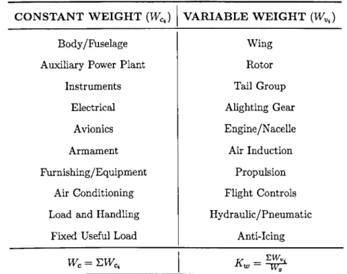
Weight analysis at this level of granularity identifies tructure and systems as functional groups. Systems such as avionics, instrument and electrical equipment as well as fuselage structure and furnishing are incorporated in the constant weight component since they only depend on the passenger capacity and the specific level of technological advancement applied to the vehicle (Figure 2.2). The remaining load carrying structures as well as systems such as propulsion, flight controls and landing gear are included in the varying weight component (Table 2.1).
TABLE 2.1: Identification of functional weight groups for the Fixed Fraction Method (Scott and Nguyen, 1996).
CONSTANT WEIGHT (WcJ
I
VARIABLE WEIGHT (WvJBody /Fuselage Auxiliary Power Plant
Instruments Electrical Avionics Armament Furnishing/Equipment Air Conditioning Load and Handling
Fixed Useful Load
Wing Rotor Tail Group Alighting Gear Engine
/N
acelle Air Induction Propulsion Flight Controls Hydraulic /Pneumatic Anti-IcingRather than being used for a detailed weight analysis, methods like this provide a quick estimation of the efficiency of a particular design. In this case it is useful to adopt the ratio of the Operational Weight Empty to Maximum Take-Off Weight (OWE/MTOW) to compare the performance of a particular configuration to that of aircraft employed for similar purposes. The method assumes conventional commercial transports to be characterized by 54 percent of variable weight components and the remaining 46 percent related to fixed weight structures and systems. In addition to this, the use of the Fixed Fraction Method allows for an easier definition of the design space being explored, for a ready identification of the parameters with the highest degree of influence on the desired performance characteristics of the design as well as highlighting the possible consequences of changing any of these parameters in the configuration. This can be readily seen in the incorporation of the Breguets equation for range in the computation of the aircraft gross weight (Equation 2.9).
W g -_ Wc+Wpl R
where:
Kwev correlates variable and gross weight in the same way as Kw in the method of Scott and Nguyen (1996);
Krsv is a factor used to include the effects of reserve fuel on gross weight; R indicates the design range of the aircraft.
C allows to account for engine performance and depends on the type of engine used in the design (Equation 2.10, 2.11):
C
= 326 x(~)
(S
;C )
for propeller driven aircraft (2.10)for jet powered aircraft (2.11)
where:
15
is the lift to drag ratio of the design; n is the cruise efficiency for the propeller;SFC is the average cruise specific fuel consumption for propeller driven aircraft;
TSFC is the average cruise thrust specific fuel consumption for jet powered aircraft.
This is a particular adaptation of the relationship between range and gross weight as presented by Bechdolt et al. (1996). Each empirical method will have a similar formulation incorporating other parameters according to the focus of the particular study. Equation (2.8), for instance, identifies payload and constant weight component as the main driving parameters for range and, consequently, for fuel reserve. Scott and Nguyen (1996) provide an equivalent type of relationship (Equation 2.12).
w _
Wc+Wpl9 - R
Kca
x (1
+ Kwev)
x 10c -
(Kwev + Kr8v )where:
Kca is a correlation factor allowing for extra fuel burnt during climb and accel-eration.
The main layout of the formulation mirrors (Equation 2.9), however in this case it has been rearranged to include the effect of climbing performance on take-off weight through the correction factor.
Of a similar degree of simplicity is the risk analysis carried out for this type of methodologies. One of the first examples of the quantification of the "risk" of using a particular WER was conducted by Ballhaus (1947) who adopted probability theory to enhance the applicability of empirical WERs at aircraft subsystem level. In particular, the study focuses on examining first the effects of the individual geometrical or opera-tional parameters chosen by the designer on the subsystem weight and, subsequently, their combined impact. Once the WERs are derived, probability theory is then applied to compute the probable error of estimate that can be expected from the formulation based on the analysis of the given statistical data. Although still basic in both the structure of the WERs and the application of the theory of probability for the solution of the problem, BaUhaus {1947} showed the first real attempt to assist the designer in judging the validity and applicability of their weight estimates.
Scott and Nguyen (1996) prefer the Growth Factor (GF) approach as a first attempt to risk analysis for empirical weight estimation at preliminary design stages. Through the computation of the GF, it is possible to estimate the relationship between increments in empty weight and desired level of performance of the design. In par-ticular, this parameter was proven successful in determining the degree of impact of different weight variations in less than one-tenth of the time required by other statistical methods and with greater accuracy (Equation 2.13).
GF
=
(Cgf) 1+
Krs~
Kca x (1