An Efficient Wavelength Assignment Technique for the
Reduction of Blocking Probability in WDM/DWDM
An Efficient Wavelength Assignment Technique
for the Reduction of Blocking Probability in
WDM/DWDM Network
Thesis submitted to
National Institute of Technology, Rourkela for the award of the degree
of
Master of Technology
in
Electronics and Communication Engineering Specialization: Communication and Networks
by
Saroj Kumar Mahapatra Roll No: 213EC5247
under the guidance of Prof. S. K. Das
Declaration
I certify that
a. the work contained in this thesis is original and has been done by me under the guidance of my supervisor.
b. the work has not been submitted to any other Institute for any degree or diploma.
c. I have followed the guidelines provided by the Institute in preparing the thesis. d. I have conformed to the norms and guidelines given in the Ethical Code of
Conduct of the Institute.
e. whenever I have used materials (data, theoretical analysis, figures, and text) from other sources, I have given due credit to them by citing them in the text of the thesis and giving their details in the references. Further, I have taken permission from the copyright owners of the sources, whenever necessary.
Dept. of Electronics
&
Communication Engineering
National Institute of Technology Rourkela
Rourkela-769 008, Odisha, India. www.nitrkl.ac.in
Certificate
This is to certify that the thesis entitled,An Efficient Wavelength Assignment Tech-nique for the Reduction of Blocking Probability in WDM/DWDM Network, submitted by Saroj Kumar Mahapatrato National Institute of Technology Rourkela, is a record of bonafide research work carried under my supervision and is worthy of con-sideration for the award of the degree of Master of Technology of the Institute.
Dr. S. K. Das
Assistant Professor
Acknowledgments
First of all I would like to thank my almighty god ’SAI BABA’, without his blessings I wouldn’t have been writing these acknowledgments. This thesis work would not have been possible without the guidance and the help of several individuals who in one way or another, contributed and extended their valuable assistance in the course of my research work. My utmost gratitude to Prof. S. K. Das, my dissertation adviser whose sincerity and encouragement. I will never forgetProf. Daswho has been my inspiration as I hurdle all the obstacles in the completion of this research work and has supported me throughout my project work with patience and knowledge whilst allowing me the room to work in my own paradigms. I would like to express my humble respects to Prof. S.K.Patra, Prof. S. K. Behera, Prof. S. Desmukh, Prof. S. Maity, and Prof. S. Hiremath for teaching me and also helping me how to learn. I would like to thank all faculty members and staffs of ECE department for their consistent help and guidance. I would like to thank all my friends and especially my classmates for all the thoughtful and mind stimulating discussions we had, which prompted me to think beyond the obvious. I’ve enjoyed their companionship so much during my stay at NIT, Rourkela. I am especially indebted to my parents for their love, sacrifice, and support. They are my first teachers after I came to this world and have set great examples for me about how to live, study, and work.
Abbreviations
AR Adaptive Routing APD Avalanche Photo Diodes
ASE Amplifier Spontaneous Emission BEP Bit Error Probability
BER Bit Error Rate CD Chromatic Dispersion
CWDM Coarse Wavelength Division Multiplexing DWDM Dense Wavelength Division Multiplexing EWA Existing Wavelength Assignment
FAR Fixed Alternate Routing FC Filter Concatenation
FFWA First-Fit Wavelength Assignment FR Fixed Routing
FWM Four-wave Mixing FWMR Four-wave Mixing Ratio
LASER Light Amplification by Stimulated Emission of Ra-diation
LED Light Emitting Diode LC Linear Crosstalk LI Linear Impairment MD Modal Dispersion NLI Non-linear Impairment PLI Physical Layer Impairment PMD Polarization Mode Dispersion PDL Polarization Dependent Loss PWA Proposed Wavelength Assignment RWA Routing and Wavelength Assignment
List of Abbreviations
SBS Stimulated Brillouin Scattering WDM Wavelength Division Multiplexing WA Wavelength Assignment
XPM Cross-Phase Modulation
List of Important Symbols
(s, d) Source-destination pair for a connection request
n1 Refractive index of core n2 Refractive index of cladding c Velocity of light in m/s
V Frequency parameter in a fiber link inHz a Diameter of the core inµm
∆ Change in refractive index
BP Blocking probability
α Attenuation constant indB
Pds Signal power of the received/desired signal at the re-ceiver inmW
Ps Signal power at sourcesinmW
Pk Optical power of the kth interferer/crosstalk in mW
ρ Detector/receiver responsitivity
Ith Detection threshold inmA
λp,q,r FWM component generated for pth, qth and rth wave-lengths
M Number of FWM component
Ppqr(i, j) FWM power in an optical link (i, j) in mW
γ Non-linear coefficient in (w.km)−1
Lef f Effective fiber length in km
Aef f Effective area incm2
η Efficiency of the FWM
βpqr Phase-matching factor
Dc Fiber chromatic dispersion inps/nm−km
σF W M Induced noise power indB
List of Figures
2.1 A simple WDM based optical network. . . 6
2.2 An optical coupler (a), (b) cross state (c) bar state. . . 7
2.3 Block diagram of optical receiver . . . 8
2.4 Classification of PLIs in WDM/DWDM network . . . 10
2.5 The pulse broadening due to dispersion effect . . . 10
2.6 Signal with in-band crosstalk . . . 12
2.7 SPM and XPM effect in optical fiber . . . 13
2.8 FWM effect between wavelengths . . . 14
3.1 FWM component distribution inside transmission window. . . 18
3.2 Placement of long and short lightpath inside transmission window. . . 19
3.3 Transmission window partitions for N=4, 8 and 16 . . . 20
3.4 A general flow chart for FWM aware RWA . . . 23
3.5 Flow chart for PWA scheme . . . 24
4.1 The NSFNet topology . . . 28
4.2 Connection blocking probability vs. no. of wavelengths used per link . . . . 30
4.3 Blocking probability vs. no. of connection request for (s, d) pair: (1,3) . . . 31
4.4 Blocking probability vs. no. of connection request for (s, d) pair: (1,8) . . . 32
4.5 Blocking probability vs. no. of connection request for (s, d) pair: (3,7) . . . 33
4.6 Blocking probability vs. no. of connection request for (s, d) pair: (3,8) . . . 33
4.7 No of connections accepted for node pairs (3, 5), (2, 9) and (6, 7) . . . 34
Abstract
v
iewing on the rising demand and keeping eye on the expected future market of telecommunication industry, now a days all the service providers are much more focused on the efficiency part of their network system. The technique of routing and wavelength assignment (RWA) in a WDM/DWDM network is closely related to the performance of the network and ultimately the efficiency of the entire network system is based on it. Where, all the service providers trying hard to maintain a satisfactory level of transmission quality, there various types of physical layer impairments are obstacles for them. This research work proposes a technique for the reduction of four-wave mixing (FWM) effect by using an efficient RWA scheme for WDM/DWDM networks. However, we have gone through numbers of RWA schemes from various literature and found those are less efficient to provide better quality of transmission. In this thesis, we have proposed a WA scheme which partitions the entire fiber transmission window into ’N’ number of bands and assigns wavelength randomly from any one of the band based on connection length. Finally, the analytical result proves that, this mechanism reduces the FWM effect significantly which is computed in terms of blocking probability. It says higher the partition, lower the FWM effect.Keywords: WDM, DWDM, FWM, RWA, Blocking probability, Fiber transmission win-dow.
Contents
Title i Declaration v Certificate vii Acknowledgements ix List of Abbreviations xList of Important Symbols xiii
List of Figures xv
Abstract xvii
1 Introduction 1
1.1 Introduction . . . 2
1.2 Literature Survey . . . 2
1.3 Objective of the Thesis . . . 3
1.4 Organization of the Thesis . . . 4
2 Basic Concepts 5 2.1 WDM/DWDM Network . . . 6
2.2 Overview of PLIs . . . 9
2.2.1 Linear impairments . . . 9
2.2.2 Nonlinear impairments . . . 12
2.3 Routing and Wavelength Assignment . . . 15
CONTENTS
3 System Design 17
3.1 Transmission Window Partitioning Mechanism . . . 18 3.2 FWM Aware Bit Error Rate Calculation . . . 23
4 Simulation and Results 27
4.1 The Topology Model . . . 28 4.2 Simulation results for blocking probability w.r.t variation in number of
wave-lengths . . . 29 4.3 Simulation results for blocking probability w.r.t variation in number of
con-nection requests . . . 29 4.4 Simulation results for no of connections set up for different node pairs at
different wavelengths . . . 31
5 Conclusion and Future Work 35
5.1 Conclusion . . . 36 5.2 Future work . . . 36
References 37
C H A P T E R
1
Introduction
3
Preface
This chapter presents a brief introduction to the concept of FWM effect over WDM/ DWDM and in literature survey part various research works have been carried out so far
Introduction
1.1
Introduction
I
n present scenario of communication and network, the rapid increase in user number is a big challenge for all telecommunication service providers. To serve all the users in the network system and to deal with terahertz bandwidth, optical fiber communication is the ultimate solution using Wavelength Division Multiplexing (WDM) and Dense Wavelength Division Multiplexing (DWDM) technology. This technology is being used in applications such as video imaging services, medical imaging services, CPU interconnects and many more [1]. The users in WDM/DWDM network communicate with each other through optical channels, so called lightpath. The lightpath consists of multiple fiber links and is set up only when it occupies the same wavelength through all the fiber links [2]. When more number of channels will present inside fiber transmission window, they interact more. This breeds four-wave mixing (FWM) effect, which causes degradation in transmission quality [3]. The degradation in service quality due to impairments is a big headache to all service providers. The advancement in technology is in process to get rid of this problem.1.2
Literature Survey
To meet the rising demand of the network usage, the capacity of the network must be upgraded. Upgradation of capacity means focusing on the data transfer rate and the num-ber of channels used in optical finum-ber. If we will go for increasing the data transfer rate than it needs replacement of all electronic end equipments of the entire fiber network, which will become a matter of concern for industry. If we will allow more WDM/DWDM chan-nels inside the optical fiber transmission window than due to insufficient space between channels, causes generation of FWM effect. Increasing the data-rate (above 40 Gbps) breeds chromatic and polarization-mode dispersion effect which have highest impact on BER performance of lightpaths in an optical fiber system [4].
Also many research works have been conducted to bring down FWM effect in fiber transmission window. To reduce FWM interference/interaction a theory related to FWM ratio (FWMR) has been proposed by M. Ali [5]. The ratio between the optical signal power to FWM power at the receiving end of a lightpath is known as FWM ratio. When the network receives one request for data transfer, then there will be many options/lightpaths available for connection set up. The F W M R−1 for all wavelengths/lightpaths are cal-culated. The lightpath which is having least F W M R−1 is marked as the shortest path
between source and destination node and this was done by using Dijkstra’s algorithm . 2
1.3 Objective of the Thesis
The FWM effect can be avoided by putting unequal space between the channels. It has been proposed in [6–8]. But it creates more unused space inside fiber transmission window and unnecessarily the efficiency is degraded.
Another kind of theory to reduce FWM effect has been proposed in [9] where a call admission control (CAC) scheme was designed. This theory represents two algorithms (a) relaxed algorithm (RA), (b) strict algorithm (SA). Both the algorithms were used to estimate FWM effect for lightpaths in different manner and they do not allow lightpaths to degrade its quality below a level, called a threshold level.
Keeping in the mind that, the FWM components have a tendency to populate them-selves in the central part of the fiber transmission window in comparison with the side edges. To avoid FWM interference for the channels in the central region [3], Aneek adhya and Debasish dutta have proposed a model where short lightpaths are placed in the cen-tral part of the window and the long lightpaths on the sides. The lightpaths having short length will interact for less time period, so the FWM effect reduces considerably unlike long lightpaths.
1.3
Objective of the Thesis
The objectives of this research work are
• To discuss FWM aware light-path selection mechanism and to calculate bit error probability of each lightpath in presence of FWM effect.
• To explain the fiber transmission window partitioning mechanism.
• To measure the performance of the network by calculating its connection blocking probability with respect to change in number of wavelengths, connection requests.
Introduction
1.4
Organization of the Thesis
Following to introduction, the thesis is organized as follows:
Chapter 2: It gives a basic introduction to WDM/DWDM networks along with the var-ious components used in its networks. Knowledge about different kind of physical layer impairments has been presented. Various routing and wavelength assignment techniques have been discussed.
Chapter 3: This discusses bit error rate calculation for a lightpath in presence of FWM effect and the transmission window partitioning mechanism as per our designed PWA schemes.
Chapter 4: This chapter explains about the topology model along with various assump-tions considered during simulation and finally the simulation results have been discussed.
Chapter 5: This chapter draws a conclusion relating to the outcomes of simulation and presents the future scope of this work.
3
C H A P T E R
2
Basic Concepts
3
Preface
This chapter presents the detail discussion on WDM/DWDM network and its various components. It gives an idea of different kind of linear and non linear impairments. Lastly
Basic Concepts
2.1
WDM/DWDM Network
T
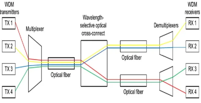
he technology used in WDM is to divide the entire bandwidth in to different wave-lengths and then each wavelength is dedicated to provide service to source-destination node pair. In this way the capacity of WDM is used efficiently. The network has both transmitter and receiver end. The wavelengths are multiplexed at the transmitter end and de-multiplexed at the receiver end [10]. A diagram of a simple WDM transmission system has been shown in figure 2.1 below. The main components of a WDM network are optical fiber, transmitter, receiver, filter, multiplexer, amplifier, switch and wavelength converter.Figure 2.1: A simple WDM based optical network.
Optical fiber cable: The optical fiber cable comprises of core and cladding. The light rays in the form of wave travels through the core from one end to the other and during propagation, it gets reflected from the border between the core and the cladding which causes loss. This is known as total internal reflection effect. The refractive indices of core and cladding are different, denoted as n1 and n2. The refractive index of core is greater than the refractive index of cladding;n1> n2. The refractive index of an optical medium can be defined as the ratio of light speed in vacuum to the speed of light in that particular medium. The light speed in vacuum is 3×10⁸ m/s. When a light ray hits the border between core and cladding with incident angle θ, a part of it reflects back to medium 1(core) with reflective angle α, while the other part refracts to medium 2 (cladding)
2.1 WDM/DWDM Network
ing a refractive angleβ. The relationship between the incident and refractive α and β is defined by Snell’s law: n2/n1 =sinα/sinβ. If the angle of incidenceαis above the angleθ
which is called critical angle, then no light will pass to the other medium and the beam is reflected. The value of critical angle θ=arcsin(n2/n1). The fiber window is used within 1310 and 1550 nm, the attenuation are about 0.5 and 0.25 dB/km respectively [10].
Optical couplers: An optical coupler is a device used in WDM network, which combines or splits the signals. The optical coupler can be a passive or active one. Basically it fol-lows optoelectrical conversion technology. The passive couplers do not go for optoelectrical conversion to redistribute signals. A passive directional 2×2 coupler is shown in Figure 2.2 (a). The optical coupler can have cross and bar state, and this classification is based on coupling between the waveguides. Generally all the input power on one waveguide is coupled to another in cross state, but for bar state there is no coupling between waveg-uides. Figure 2.2 (b) and (c) shows the cross and bar state [10].
Figure 2.2: An optical coupler (a), (b) cross state (c) bar state.
Optical amplifiers: These are used in networks to limitize the fiber attenuation for long route transmission. The three most used amplifiers are
• Erbium-doped fiber amplifiers(EDFA)
• Raman amplifiers
• Semiconductor optical amplifiers
The EDFA is used in WDM networks to amplify optical signals by using erbium-doped optical fiber as gain medium. The fiber core is doped with atoms which are erbium charged to shift the energy between discrete levels. The second type of amplifier is Raman amplifier. Its signal amplification technique is based on the stimulated Raman scattering (SRS) effect. The SRS is having a harmful effect on WDM systems, but it is found very
Basic Concepts
in which population inversion is done by the application of external voltage [10].
Optical transmitter: Two types of transmitters are used in optical communication system i.e. light emitting diode (LED) and laser. The operational procedure of LED is based on spontaneous emission of light. The generated light is purely incoherent in nature and comprises of many wavelengths with different phases. The LED produces light wave with broad spectrum and having low power. The Laser generates coherent light, i.e. light is having wavelengths of finite number at the same phase. The operational principle is based on stimulated emission of photons, which is best outlined with the fact that its name comes from LASER(light amplification by stimulated emission of radiation) [10].
Optical receiver: The optical receivers are the photo detectors which transform the optical signal to electrical signal. A photo detector detects a desired wavelength and converts the incoming photon stream into electrons with a fast response and low noise and temperature sensitivity. Most commonly used photo detectors are photodiodes, i.e. intrinsic p-n diodes (PIN) and avalanche photo diodes (APD) [10]. As shown in the fig 2.3 the incoming optical signal is pre-amplified by the optical amplifier, than it is fed in to the optical filter to cut the noise level by selecting the desired wavelength. Optical signal is transformed to electrical signal by the photo detector, than it is fed to post amplifier. An equalizer is needed to compensate the inter symbol interference. To pull out the received signal, a recovery clock circuit is used in the decision circuit. At last the sampled signal is compared with the pre-set threshold. Decision circuit sets the received signal sample to bit 1 or to bit 0 after comparing with threshold.
Figure 2.3: Block diagram of optical receiver
Optical filter: The Optical filter separates and selects signals of particular wave-lengths. The optical filter is of two types. First one is based on optical interference and
2.2 Overview of PLIs
it uses optical diffraction. The second one is based on the possibility of tuning the wave-lengths which will be filtered out [10].
Dense Wavelength Division Multiplexing (DWDM): Dense wavelength division multiplexing (DWDM) is the advancement of WDM, used in current fiber optics com-munication industry. Both DWDM and CWDM use WDM technology to allow many numbers of lightwaves to transmit through same single optical fiber cable simultaneously. As compared to CWDM (coarse wavelength division multiplexing), DWDM carry more fiber channels. By using DWDM technology, data can be transferred at a speed of 400Gb/s in a single channel. The DWDM is most advantageous because, its protocols do not relate with data transfer rate [10]. So the protocols like IP, ATM, SONET/SDH, Ethernet are used in DWDM and the data transfer rate between 100Mb/s to 2.5Gb/s. Even this tech-nology allows transmission of different data streams at different transfer rate in the same channel.
2.2
Overview of PLIs
The physical layer impairments (PLIs) in optical fiber communication are of two types: linear and non-linear impairments [11–13]. The linear impairments (LIs) are basically intensity-independent, static and non-linear impairments (NLIs) are intensity dependent, dynamic in nature. The NLIs depend on the current allocation of route and wavelength. They affect optical channel and cause disturbances. LIs do not depend on the signal power and affect each channel one by one during transmission [14].
2.2.1 Linear impairments
As shown in figure 2.4 the important LIs are: fiber attenuation, component insertion loss, amplifier spontaneous emission (ASE) noise, chromatic dispersion (CD), polarization mode dispersion (PMD), polarization dependent losses (PDL), crosstalk (XT) (both inter-and intra-channel) inter-and filter concatenation (FC). Let us discuss all these in brief.
Polarization Mode Dispersion (PMD): PMD is generated because of the presence of geometric irregularities along the optical fiber and it is very common in fiber optic communication. The irregularities like bending, twisting or pinching of the fiber generates various polarizations and due to that reason signal traverses in different velocities and
Basic Concepts
Figure 2.4: Classification of PLIs in WDM/DWDM network
a delay called differential time delay is introduced in between two modes. The PMD is completely random in nature. The differential group delay introduced by the non-ideal fiber may be calculated asT P M D=DP M D∗√L,where DP M D is a PMD parameter measured inps/√km. As it is dependent on square root of length, pulse broadening gets introduced but effect is less in comparision with CD. The normal PMD value range is in between 0.01-10ps/√km [11–13,15]. It can be a major problem creator for higher bit rate long distance WDM systems.
Figure 2.5: The pulse broadening due to dispersion effect 10
2.2 Overview of PLIs
Chromatic Dispersion (CD):It is also known as intramodal dispersion and is gen-erated in single mode fiber. The spreading is due to the finite width of spectral emission in optical source. If the width of spectral emission increases the dispersion will go up [11]. Chromatic dispersion causes broadening in pulse and that is why it spreads on other pulses and their time slots get affected. This one is regarded as the major limitation for high speed (above 2.5Gb/s) network system. It is also known as material dispersion. Mate-rial dispersion is generated when refractive index of core varies and it is considered as function of wavelength. The spreading of pulse generated because of CD is expressed as
T CD=DCD∗λ∗LhereDCD is the dispersion coefficient,Llength of the fiber link and
λis the wavelength assigned to the fiber link.
Polarization Dependent Loss (PDL):There are two components of polarization which are along the two number of axes in a circular fiber suffer different rates of loss due to presence of irregularities in fiber; therefore the signal quality is degraded, which is not controllable. Due to this, fluctuations get introduced in OSNR(optical signal-to-noise ra-tio). It is measured as the ratio between peak-to-peak difference in transmission and all possible polarization states. This is written as P DLdB = 10log(Pmax/Pmin), where Pmax is maximum and Pmin is minimum power output. This thing is found in optical compo-nents which are passive [1].
Linear Crosstalk (LC):LC is generated because of incompletion of isolation in WDM/ DWDM connection of optical components like OADMs, OXCs, multiplexer/de-multiplexer and optical switches. It occurs because of leakage in power on the desired connection/ light wave from other connections/lightwave. LC is of two types: out-band (OB) or in-band (IB) [16]. IB crosstalk has adverse effect as compared to OB crosstalk because it will lie in the same band of frequency as of the desired signal. In ideal case, there is no crosstalk as two signals are routed to different output ports. However, any leakage or in-sufficient isolation induces homodyne crosstalk.
Filter Concatenation (FC): The FC effect is generated when the signal’s spectral width gets narrowed, when traverses through a set of filters along a connection. Also FC depends on three things: one is route, second is the type of modulation used and third is how many optical components up to destination end when signal moves from source to destination.
Amplifier Spontaneous Noise: The optical amplifiers which are connected as inter-mediate nodes, like repeaters or preamplifier and this device produces noise before the
Basic Concepts
Figure 2.6: Signal with in-band crosstalk
density and is often specified in decibels (dB). The ASE works both in forward as well as backward direction but during propagation the forward noise will interact with the signal and ultimately the performance is degraded.
Modal dispersion (MD): Modal dispersion is a predominant LI in multimode fiber. Different modes having different propagation constant take various path available in fiber and travelling down different length in the fiber. This results delay in time period among different modes and due to this, spreading of pulse is occurred. If a graded index and step index fiber of same size are taken for use than modal dispersion is found more in step index fiber than graded index [13].
Waveguide dispersion: This effect is generated due to interaction among waveguide’s physical dimension and the light pulse. Out of single mode and multi-mode fiber, single mode fiber gets affected by waveguide dispersion. In fiber optic communication the light passes through core of the fiber but about 20 percent of light energy in the form of signal power travels in fiber cladding. In optical fiber, this waveguide is represented as propaga-tion constant of a mode and is equal to a/λ, a is the radius of core in fiber and λ signal wavelength [11].
2.2.2 Nonlinear impairments
As mentioned in the figure 2.4 the block diagram of classification of PLIs, the important non-linear impairments (NLIs) are self-phase modulation (SPM), cross phase modulation
2.2 Overview of PLIs
(CPM), four wave mixing (FWM), Stimulated Brillouin Scattering (SBS) and Stimulated Raman Scattering (SRS). The following sections describe in detail.
Self-phase modulation (SPM):The SPM is generated when light and matter interact with each other. A light pulse which is short one, when traverses in a medium, it gets introduced with variation of refractive index in the fiber due to an effect called the optical Kerr effect. When it traverses, if the light pulse will have higher intensity than a portion of a light pulse gets encountered by fiber of refractive index of higher value as compared to the portion having lower intensity. This variation in refractive index breeds a phase shift in pulse. Therefore, the changes in frequency spectrum of pulse occurs. SPM uses small, intense pulses of light, such as laser.
Cross phase modulation (XPM): When one wavelength of light affects the phase of another wavelength of light then this effect is known as XPM, also known as optical kerr effect. The phase modulation in one optical pulse occurs due to amplitude of another pulse. It causes
• Cross talk in between channels
• Timing jitter in the fiber medium
The XPM effect is directly proportional to the channel numbers if those are more and degradation occurs more than SPM.
Figure 2.7: SPM and XPM effect in optical fiber
Stimulated Raman scattering (SRS): This effect degrades the signal at lower wavelength. In SRS lower wavelength signal power transforms to higher wavelength signal. So the SNR of lower wavelength signal reduces.
Basic Concepts
the process of scattering is stimulated by photons. All these photons are associated with higher wavelength rather than the incident signal wavelength.
Four-wave mixing (FWM): It is a phenomenon in fiber networks wherein light waves interact to produce a new one likewise when two or more wavelengths interact among themselves and generate the new one [3, 17, 18]. If three frequenciesfp,fq andfr interact, they generate new light waves of the frequencyfpqr =fp±fq±fr. Wherep, q, r∈[1, M],r̸=
p, q with M is the number wavelength in a WDM link. IfM number of wavelengths co-propagate thanM2(M −1)/2 number of FWM components will be generated [3, 17]. So assuming 3 frequencies, which will generate total of 9 FWM components i.e. f1 +f2− f3, f1+f3−f2, f3+f2−f1,2f1−f2,2f1−f3,2f2−f1,2f2−f3,2f3−f1,2f3−f2. Out of these 9 components f1+f2 −f3, f1+f3 −f2, f3+f2 −f1 will lie in different bands,
but2f1−f2,2f1−f3 will lie in origin band off1. Similarly 2f2−f1,2f2−f3 will interact
withf2 and 2f3−f1,2f3−f2 withf3. For 4 no. of wavelengths, there will be total 24 no. of FWM components.
Figure 2.8: FWM effect between wavelengths
This effect is independent of the data transfer rate [4,19] but it depends on the channel spacing, dispersion present in fiber and walk off period of the wavelengths. The increment of FWM effect is inversely proportional to channel spacing. It is having severe impact on a WDM system, when network uses dispersion-shifted fiber. This is the reason WDM systems uses non-zero dispersion-shifted fiber to minimize this effect. There is another way this effect can be minimized by allowing unequal space between channel to avoid in-terference between the generated signals with the original signals.
2.3 Routing and Wavelength Assignment
2.3
Routing and Wavelength Assignment
Routing and wavelength assignment (RWA) signifies a process of setting up a connec-tion between a source-destinaconnec-tion node pair followed by assigning wavelength [20, 21] to that connection. An optical fiber cable using WDM/DWDM technology can accommo-date up to 120 wavelengths. This capacity will be more in near future [22]. The RWA signifies two processes. Firstly by using a routing technique, find a connection for a source-destination node pair and secondly assign a wavelength on the selected connection by using an algorithm called wavelength assignment algorithm.
2.3.1 Routing Techniques
There are two types of routing techniques. Those are discussed below
Fixed Routing (FR):In this technique when a source-destination node pair is initialized than only one light path is established [2]. The major drawback of it is that, due to lack of light paths it shows high blocking probability.
Adaptive Routing (AR): Using this technique, all the possible connections are found out online initially. This finding is dependent on network state and resources availabil-ity [23]. A connection is set up dynamically but it depends on network state. When the network receives the connection request, the shortest connection is computed out of all possible connections. If the algorithm finds more than one connections having equal dis-tance, then the path is selected randomly and blocked when connection is not available. This technique is mostly used in WDM/DWDM network and also being used in our work.
2.3.2 Wavelength Assignment Algorithm
Assignment of wavelength is the post work of connection selection and it is carried out by using various algorithm illustrated below.
Random WA: Out of many wavelengths one wavelength is taken randomly. In actual scenario the algorithm generates a number randomly and wavelength is assigned to it.
First-Fit WA (FFWA): In this method, all available wavelengths, are arranged in as-cending order. Then the first lightpath connection is served by the least number wave-length. The blocking probability is low in this case because it works in a disciplined
Basic Concepts
2.3.3 Network Traffic in WDM/DWDM Network
In a WDM/DWDM network, the network traffic pattern is of two types static and dynamic.
Static pattern: In this pattern, the network has prior information/knowledge about the path; the source-destination pair to be used at a particular moment and it remain for a period of time. So the network adopts reservation scheme for this.
Dynamic pattern: In this mechanism any number of connection requests may be arrived to network at any point of time and to serve it, network will not adopt any reservation scheme. Each light path is served as it arrives and it is released after a period of time. Gen-erally this method is being adopted by all service providers now-a-days. Also the RWA faces various constraints, those are wavelength continuity, wavelength distinct, physical layer impairment and traffic engineering.
3
C H A P T E R
3
System Design
3
Preface
System Design
3.1
Transmission Window Partitioning Mechanism
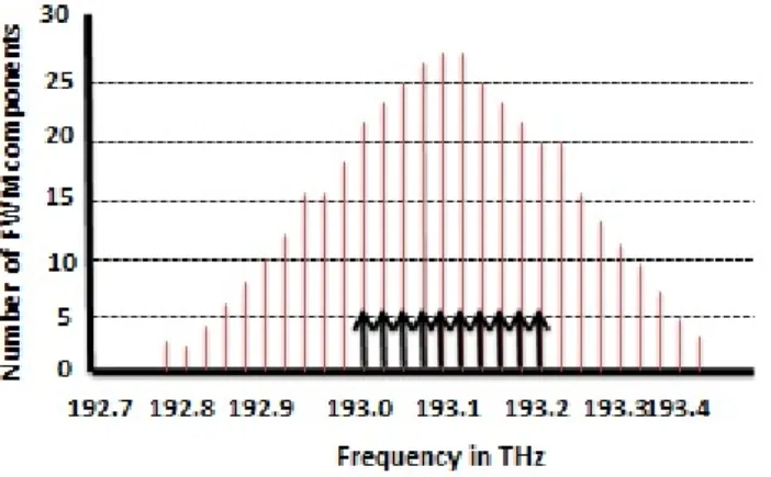
A light path is established means, light has to travel through many number of links. In every link the same lightpath gets encountered by different wavelengths. So for the same lightpath the FWM power/components will vary from one link to another link. FWM effect is zero when the lightpath starts travelling and this effect gets accumulated in each link throughout its route [17]. Let us consider WDM system where all channels are equally spaced, the FWM components will be gathered more in the central part of the transmission window than the edges [3,6]. The below figure shows the distribution of FWM components of a WDM link. Here in figure 10 channels are travelling together and their frequencies range is 193.0 THz to 193.225 THz and space between each channel is 25 GHz.
Figure 3.1: FWM component distribution inside transmission window.
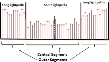
Referring to the above example, large number of generated components are gathered automatically in the center part of the window rather than extreme edges. The channels are allocated in the central part of the window will experience more FWM effect, than placed in the sides of the window. Using this observation, aneek adhya and debasish dutta have proposed a model, where short lightpaths are placed in the central segment of the window and the long lightpaths on the side edges (outer segments), to bring down the FWM effect at the central region as shown in figure 3.2.
The wavelengths from these segments are allocated to a connection. It is defined as ex-18
3.1 Transmission Window Partitioning Mechanism
Figure 3.2: Placement of long and short lightpath inside transmission window.
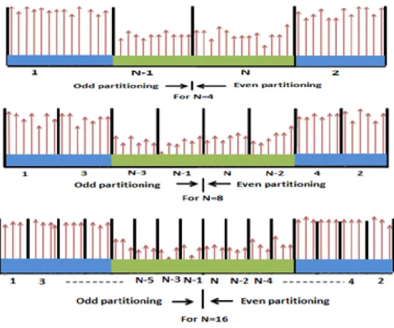
isting wavelength assignment (EWA) technique for FWM. In our case, we designed a new WA scheme based onN number of partitions in transmission window. These partitioning are named as equal number of odd and even partitioning. If there is N partitioning, than the name of the bands will be 1,2,3,4..., N−2, N −1 andN.
The proposed partitioning mechanism divides the transmission window in to N number of partitions. It has N/2 number of odd bands named as band 1,3,5, . . .(N−3),(N−1). Similarly it has also N/2 number of even bands named as 2,4,6,(N−4),(N −2) and N.
Referring to figure 3.4 whenever, a WDM network receives a connection request than it initializes the node pair containing the source node and destination node for the respective connection request. First the network tries to compute all the possible paths between the source and destination node pair. Those possible paths are arranged in a sorted order. Then, it picks the first possible path and assign wavelength using PWA schemes. Assign-ment of wavelength using PWA scheme has been shown detail in figure 3.5. The BERis calculated each time for the same path under different schemes. If the calculated BER is less than the threshold BER which is fixed 10−9than that connection will be accepted and network will switch to another connection request. But if it finds that calculatedBERis greater than the threshold BERthan it rejects that connection and tries for another one and so on. This stops when there is no more connection request.
de-System Design
Figure 3.3: Transmission window partitions for N=4, 8 and 16 .
wavelengths in inner bands. Algorithm 3.1 will call algorithm 3.2 during its operation. Algorithm 3.2 will call algorithm 3.3 during assigning wavelengths in inner bands.
3.1 Transmission Window Partitioning Mechanism
Algorithm 3.1: FWM aware RWA
1: {Data: Simulation Network Topology, Parameters For
Simulation,s,d,ConnectionRequests,BERthrs,P artitionsN = 4,8,16,
AllP ossibleConnections Result: BER,Connectionaccept,
W avelength assignment}
2: Initialize (s, d) = () and take the firstconnectionrequest
3: for cr=1 toCR do
4: Get AllP ossibleConnectionsand take the first connection
5: forc=1 toC do
6: W avelengthAssignmentusing PWA schemes
7: forN = 4,8,16 do
8: Compute BERfor each connection
9: if BER < BERthrs then
10: Accept assign theconnectiontorequestand go for next request
11: else
12: Rejectconnectionand go for next connection
13: end if
14: end for
15: end for
16: end for
As illustrated in figure 3.5 the threshold/average distancedthrsfor all existingK num-ber of connections is calculated. Initially the numnum-ber of connections established, L = 0 and number of connections blocked, M = 0. HereN is the number of partitions to be ob-tained inside fiber transmission window. Considering the first connection having distance d, if it is greater than the threshold distance than it will try to assign from (2n−1)th and (2n)th bands for n values 1,2, . . . Nmax/4. The (2n−1)th bands forn value 1,2, ..Nmax/2 are odd partitioned bands. Similarly the (2n)th bands for n value 1,2, ..N
max/2 are even partitioned bands. Here wavelength assignment task for connections is carried out in a sequential order. The connection comes first to thed > dthrs section is treated as first and odd one, the next connection comes in, is the second and even one, the next is third and odd one and this sequence is followed in equal manner ford < dthrssection. When the first wavelength is assigned in any of band thanK and Lvalue is updated to K=K−1 and
L=L+ 1 respectively. The wavelength assignment may switch fromd > dthrs tod < dthrs section due to non-availability of wavelengths in earlier section. After completion of each assignment process, it checks whether K is equal to zero or not. When it finds K is not equal to zero than it goes for next connection assignment task.
wave-System Design
Algorithm 3.2: Wavelength assignment using PWA Scheme
1: { Given data:All existing Connections,d,K,L,M,S,n
Result:W avelength assignment }
2: Initialization: K,L,M,S
3: Compute dthrs out ofall existing connections
4: Take aconnectionof distance d
5: if d > dthrs then
6: Assign odd wavelengths in (2n−1)th and even wavelengths in (2n)th bands
7: for n=1 toNmax/4 do
8: forRepetition of assignment in same band at Nmax/2 gap do
9: if assignment f easible in (2n−1)th bandthen
10: k=K-1, l=L+1
11: else
12: assign in (2n)th band
13: k=K-1, l=L+1
14: else
15: for n= (Nmax/4) + 1 to (Nmax/2)do
16: forRepetition of assignment in same band at Nmax/2 gap do
17: assign in inner bands
18: if K = 0 then 19: Stop 20: end if 21: end for 22: end for 23: end if 24: end for 25: end for 26: end if
Algorithm 3.3: Assign Wavelength in inner bands
1: {Given data: All existing Connections,K,L,M,n}
2: Initialization: K,L,M
3: Assignment of odd wavelengths in (2n−1)th and even wavelengths in (2n)th bands
4: if assignment f easible in (2n−1)th bandthen
5: k=K-1, l=L+1
6: else
7: assign in (2n)th band
8: k=K-1, l=L+1
9: else
10: Block the connection
11: k=K-1,m=M+1
12: end if
not feasible in (2n)thband for any values ofn= (Nmax/4) + 1,(Nmax/4) + 2, . . . Nmax/2 than it blocks the connection and the value of M gets updated to M+1. The WA task stops when it findsK = 0.
3.2 FWM Aware Bit Error Rate Calculation
Initialize source-destination pair (s, d).Get a connection request
for (s, d) pair CR=CR +1
Compute all possible connections betn (s, d) pair & take the first
connection c=c +1
Assign wavelength using PWA schemes
Estimate the BER of the connection
Suitable for connection? i.e., BER <BERTH??
Go for next connection
Accept & assign the connection to the request
No
Yes
Go for next connection request
Figure 3.4: A general flow chart for FWM aware RWA .
System Design
Take a connection of distance=d Total no. of connections=K No. of connections established=L
No. of connections blocked=M
If d>dthrs
WA for (2n-1) th & (2n) th bands
for n=1,2,...N max/4. WA for (2n-1) th
& (2n) th bands, for n=(Nmax/4)+1,(N max/4)+2...
..(Nmax/2). Is WA feasible in (2n-1)th band. Gap betnodd no WLs =Nmax/2 Assign wavelength from (2n-1)th band K=K-1, L=L+1 Is WA feasible in (2n)th band. Gap betn even no WLs=Nmax/2 Assign wavelength from (2n)th band K=K-1, L=L+1 Is WA feasible for (2n-1) th band.
Gap betn odd no WLs=Nmax/2 Assign wavelength from (2n-1) th band K=K-1, L=L+1 Assign wavelength from (2n) th band K=K-1, L=L+1 Block the connection K=K-1, M=M+1 If K >0 End Go for next connection Yes No Yes No Yes No Yes No No Yes No Is WA feasible for (2n)th band. Gap betn even no WLs=Nmax/2
Compute the threshold distance(d thrs)
Yes
Figure 3.5: Flow chart for PWA scheme .
three equally spaced wavelengths λp, λq and λr are moving together than a new FWM componentλp,q,r will be generated. It can be expressed as
λp,q,r =λp±λq±λr (3.1) 24
3.2 FWM Aware Bit Error Rate Calculation
where, p ̸=r and q ̸=r. In the above equation λp, λq, λr are wavelengths. If three light waves interact than there are nine number of wavelengths generated [3] and this effect is dependent on the length of duration of interaction among channels inside fiber cable and the space between channels. The FWM power [25–29]Ppqr(i, j) produces in a link (i, j) is
Ppqr(i, j) =
η
9d
2γ2P
pPqPre−αLL2ef f (3.2)
The p, q, r are index numbers; d is called degeneracy factor, d is 3, when λp = λq and 6 whenλp̸=λq ;Pp, Pq, Pr are signal input power,L is the fiber length;αis the attenuation coefficient of fiber cable; γ is the non-linear coefficient; Lef f is the effective fiber length and is calculated as
Lef f = (
1−e−αL)
α (3.3)
The efficiencyη in presence of FWM effect is represented by the equation below
η = α 2 α2+β2 pqr [ 1 +4e −αLsin2(β pqrL/2) (1−e−αL)2 ] (3.4)
According to [28, 30], the efficiency is approximated to
η = α
2 α2+β2
pqr
(3.5)
If the value of βpqr is zero than efficiency η will be 1. Theβpqr is called propagation con-stant difference which is dependent on spacing between channel as well as fiber chromatic dispersion. The propagation constant can also be represented by the equation below
βpqr = 2πcλ2k∆λpq∆λqr ×[Dc+ ( λ2 k 2 )(∆λpq+ ∆λqr) dDc(λk) dλ ] (3.6)
In the above equationλk= central wavelength, C is the speed of light,Dc the fiber chro-matic dispersion and dDc(λk)
dλ the dispersion slope. If the propagation constant difference is far from the zero dispersion region than
System Design
Hence total FWM power is
Ppqr(s, d) = ∑ (i,j)∈(s,d) ∑ p ∑ q ∑ r Ppqr(i, j) (3.8)
At receiver end the light of FWM and desired signal both are detected , so the noise power,
σF W M [28, 30] is
σF W M = 2ρ2Pds
Ppqr(s, d)
8 (3.9)
wherePds is the optical signal power of the received signal at the receiver.
Pds =Pie−αL (3.10)
In case of FWM, the bit-error rate is
BERF W M = 0.5erf c(SN RF W M) (3.11) whereSN RF W M is represented as SN RF W M = Ids σF W M √ 2 (3.12)
HereIds is the photo current and it is written asIds =ρPi,Pi is the input power andρ is the receiver’s responsivity.
C H A P T E R
4
Simulation and Results
3
Simulation and Results
4.1
The Topology Model
We used a NSFNet topology for our simulation work which contains 10 nodes and 16 links as shown in figure 4.1. The distances between the nodes are expressed as number. Those numbers are representing spans, and one span is 70 km.
Figure 4.1: The NSFNet topology
Following assumptions have been made during computation and MATLAB software has been used for all simulation work.
• The topology containing the nodes are of same type.
• All links will serve fixed number of wavelength for transmission.
• During simulation various noise effect like shot and thermal noise have been ignored.
• All links are maintaining wavelength continuity constraint.
• It is assumed that no any connection is existing in-between any source-destination pair.
• Non of the node is having wavelength conversion capability. The value of the parameters used in simulation is shown in table 4.1.
4.2 Simulation results for blocking probability w.r.t variation in number of wavelengths
Table 4.1: Parameters used in simulation
Parameters Values
Receiver’s responsivity,ρ 1
Signal current,Is 1mA
Input powers,Pp, Pq, Pr 5mW
Fiber attenuation,α 0.2dB/km
Degeneracy factor,d 3 iffi=fjand 6 iffi̸=fj
Efficiency,η 0 to 1
Chromatic dispersion,Dc 0.3 ps/nm-km
Dispersion slope,dDc/dλ 0.07ps/nm2
Central wavelength,λk 1.55µm
Nonlinear coefficient,γ 2.35(w.km)−1
Space between channels, ∆λ 25 GHz
4.2
Simulation results for blocking probability w.r.t
varia-tion in number of wavelengths
In first type of analysis, we tried to show how blocking probability changes when we bring up any changes in number of wavelengths. Referring to the figures below, each figure is meant for different source-destination (s, d) node pair comprising of existing wavelength assignment EWA(3), proposed wavelength assignment having 4, 8 and 16 partitions. Those are named as PWA(4), PWA(8) and PWA(16). The plots have been shown in figure 4.2(a), (b), (c), (d), (e) and (f) reflect that PWA schemes having better performance than EWA.
Out of all these above figures we can see that PWA scheme with 16 partitions PWA(16) performed better than others. One more thing we can bring in to notice that if we go for more partitions of the fiber transmission window than the blocking probability will grad-ually go down.
4.3
Simulation results for blocking probability w.r.t
varia-tion in number of connecvaria-tion requests
This analysis is carried out to show that how blocking probability varies with variation of connection requests at different wavelength. The node pairs (1, 3), (1, 8), (3, 7) and (3, 8) have taken for analysis. At fixed wavelength, when the number of connection requests vary from lower value to higher value it is observed that the blocking probability also
Simulation and Results
(a) (s, d) node pair: (1, 3) (b) (s, d) node pair: (1, 8)
(c) (s, d) node pair: (3, 8) (d) (s, d) node pair: (4, 7)
(e) (s, d) node pair: (4, 8) (f) (s, d) node pair: (3, 10)
Figure 4.2: Connection blocking probability vs. no. of wavelengths used per link
(1, 8), (3, 7) and (3, 8). The simulation plots are taken at different number of wavelengths such as 20, 25, 30, 35, 40, 45 and 50 respectively. The result signifies PWA scheme has less blocking probability. The figures reflect that the blocking probability moves downward with the increase in number of partitions as well as wavelengths.
4.4 Simulation results for no of connections set up for different node pairs at different wavelengths
(a) Wavelengths: 20 (b) Wavelengths: 30
(c) Wavelengths: 35 (d) Wavelengths: 40
Figure 4.3: Blocking probability vs. no. of connection request for (s, d) pair: (1,3)
4.4
Simulation results for no of connections set up for
dif-ferent node pairs at different wavelengths
The third case analyses the performance of various PWA schemes by calculating the number of connection established for a node pair. As shown in figure 4.7 and 4.8, the BER values of all established connections are above 10−9. Let us take node pairs (3, 5), (2, 9) and (6, 7) in figure 4.7 (a), (b), (c) and (d) whose numbers of possible connections are 21, 29 and 28. At 25 wavelengths, for node pair (3, 5) out of 21 connections, 13 connections for EWA are above 10−9 which are accepted, for PWA(4), 18 connections, PWA(8), 19 and
for PWA(16) all connections have been accepted and the remaining are blocked for others. When we increased the number of wavelengths to 30, 40 and 45 we have noticed that, PWA schemes performed better than EWA. If we go for more number of partitions than no of connection accepted will also increase. Similarly the number of possible connections for node pairs (1, 3), (4, 8) and (4, 7) are presented in figure 4.8 (a), (b), (c) and (d) at different wavelengths. These plots reflect that, if more wavelengths available per link,
Simulation and Results
(a) Wavelengths: 30 (b) Wavelengths: 35
(c) Wavelengths: 40 (d) Wavelengths: 45
Figure 4.4: Blocking probability vs. no. of connection request for (s, d) pair: (1,8)
4.4 Simulation results for no of connections set up for different node pairs at different wavelengths
(a) Wavelengths: 20 (b) Wavelengths: 25
(c) Wavelengths: 30 (d) Wavelengths: 35
Figure 4.5: Blocking probability vs. no. of connection request for (s, d) pair: (3,7)
(a) Wavelengths: 25 (b) Wavelengths: 30
Simulation and Results
(a) Wavelengths: 25 (b) Wavelengths: 35
(c) Wavelengths: 40 (d) Wavelengths: 45
Figure 4.7: No of connections accepted for node pairs (3, 5), (2, 9) and (6, 7)
(a) Wavelengths: 25 (b) Wavelengths: 30
(c) Wavelengths: 35 (d) Wavelengths: 40
Figure 4.8: No of connections accepted for node pairs (1, 3), (4, 8) and (4, 7)
C H A P T E R
5
Conclusion and Future Work
3
Conclusion and Future Work
5.1
Conclusion
The analytical results found in earlier chapter reflect the usefulness of transmission window partitioning over FWM crosstalk during routing and wavelength assignment in WDM/DWDM network. The PWA scheme has proved itself more effective and efficient one for WDM/DWDM networks, where there is always some FWM effect found inside fiber transmission window. This thesis demonstrates all the PWA schemes, measure the performance of the network by calculating blocking probability relating to variation in number of wavelengths and connection requests. The simulation results say that these PWA schemes can reduce the FWM effect significantly, even the lightpaths which were rejected in EWA scheme, later got accepted in PWA schemes.
5.2
Future work
Development of a simulator to reduce blocking probability using transmission window partitioning mechanism for industrial use.
References
[1] C. V. Saradhi and S. Subramaniam, “Physical layer impairment aware routing (pliar) in wdm optical networks: issues and challenges,”Communications Surveys & Tutorials, IEEE, vol. 11, no. 4, pp. 109–130, 2009.
[2] H. Zang, J. P. Jue, B. Mukherjee et al., “A review of routing and wavelength assignment approaches for wavelength-routed optical wdm networks,”Optical Networks Magazine, vol. 1, no. 1, pp. 47–60, 2000.
[3] A. Adhya and D. Datta, “Design methodology for wdm backbone networks using fwm-aware heuristic algorithm,” Optical Switching and Networking, vol. 6, no. 1, pp. 10–19, 2009. [4] M. Wu and W. I. Way, “Fiber nonlinearity limitations in ultra-dense wdm systems,”Journal
of Lightwave Technology, vol. 22, no. 6, p. 1483, 2004.
[5] M. Ali, V. Leboucher, and D. Penninckx, “Intelligent lightpath selection schemes,”ECOC’02, vol. 2, pp. 1–2, 2002.
[6] F. Forghieri, R. Tkach, and A. Chraplyvy, “Wdm systems with unequally spaced channels,” vol. 13, no. 5, pp. 889–897, 1995.
[7] D. Marcuse, A. Chraplyvy, and R. Tkach, “Effect of fiber nonlinearity on long-distance trans-mission,”Lightwave Technology, Journal of, vol. 9, no. 1, pp. 121–128, Jan 1991.
[8] W. Kwong and G.-C. Yang, “An algebraic approach to the unequal-spaced channel-allocation problem in wdm lightwave systems,”Communications, IEEE Transactions on, vol. 45, no. 3, pp. 352–359, Mar 1997.
[9] I. E. Fonseca, M. R. Ribeiro, R. Almeida, and H. Waldman, “Preserving global optical qos in fwm impaired dynamic networks,”Electronics Letters, vol. 40, no. 3, pp. 191–192, 2004. [10] M. Furdek, “Optical wdm networks key components,”
https://www.fer.unizg.hr/download/.../WDM komponente skripta.pdf. [11] G. P. Agrawal,Nonlinear fiber optics. Academic press, 2007.
[12] B. Mukherjee,Optical WDM networks. Springer Science & Business Media, 2006.
[13] R. Ramaswami and K. N. Sivarajan, “Routing and wavelength assignment in all-optical net-works,” IEEE/ACM Transactions on Networking (TON), vol. 3, no. 5, pp. 489–500, 1995. [14] C.-C. Chien and I. Lyubomirsky, “Comparison of rz versus nrz pulse shapes for optical
duobi-nary transmission,” Lightwave Technology, Journal of, vol. 25, no. 10, pp. 2953–2958, Oct 2007.
[15] S. Azodolmolky, M. Klinkowski, E. Marin, D. Careglio, J. S. Pareta, and I. Tomkos, “A survey on physical layer impairments aware routing and wavelength assignment algorithms in optical networks,” Computer Networks, vol. 53, no. 7, pp. 926 – 944, 2009.
REFERENCES
[17] A. Adhya and D. Datta, “Lightpath topology design for wavelength-routed optical networks in the presence of four-wave mixing,”Optical Communications and Networking, IEEE/OSA Journal of, vol. 4, no. 4, pp. 314–325, April 2012.
[18] V. L. Thing, P. Shum, and M. Rao, “Bandwidth-efficient wdm channel allocation for four-wave mixing-effect minimization,” Communications, IEEE Transactions on, vol. 52, no. 12, pp. 2184–2189, 2004.
[19] R. Ramamurthy and B. Mukherjee, “Fixed-alternate routing and wavelength conversion in wavelength-routed optical networks,”Networking, IEEE/ACM Transactions on, vol. 10, no. 3, pp. 351–367, June 2002.
[20] T. E. Stern and K. Bala, “Multiwavelength optical networks,”Addison-Wesley, EUA, 1999. [21] F. Lezama, G. Casta˜n´on, and A. M. Sarmiento, “Routing and wavelength assignment in all
op-tical networks using differential evolution optimization,”Photonic Network Communications, vol. 26, no. 2-3, pp. 103–119, 2013.
[22] A. Wason and R. Kaler, “Wavelength assignment algorithms for wdm optical networks,” Optik-International Journal for Light and Electron Optics, vol. 122, no. 10, pp. 877–880, 2011. [23] G.-S. Poo and A. Ding, “Blocking performance analysis on adaptive routing over wdm
networks with finite wavelength conversion capability,” Photonic Network Communications, vol. 12, no. 2, pp. 211–218, 2006.
[24] B. C. Chatterjee, N. Sarma, and P. P. Sahu, “Review and performance analysis on routing and wavelength assignment approaches for optical networks,”IETE Technical Review, vol. 30, no. 1, pp. 12–23, 2013.
[25] C. Lopes, T. Carvalho, and E. De Souza, “Fwm constraints management for lightpath estab-lishment in gmpls networks,”Lightwave Technology, Journal of, vol. 29, no. 18, pp. 2774–2779, Sept 2011.
[26] A. Marsden, A. Maruta, and K. Kitayama, “Routing and wavelength assignment encompassing fwm in wdm lightpath networks,” in Optical Network Design and Modeling, 2008. ONDM 2008. International Conference on, March 2008, pp. 1–6.
[27] U. Bhanja, S. Mahapatra, and R. Roy, “Fwm aware evolutionary programming algorithm for transparent optical networks,”Photonic Network Communications, vol. 23, no. 3, pp. 285–299, 2012.
[28] S. Das, A. Samantray, and S. Patra, “Hybrid crosstalk aware q-factor analysis for selection of optical virtual private network connection,” International Journal of Electronics, Taylor Francis.
[29] J. Tang, C. K. Siew, and L. Zhang, “Optical nonlinear effects on the performance of ip traffic over gmpls-based dwdm networks,”Computer Communications, vol. 26, no. 12, pp. 1330–1340, 2003.
[30] A. Bogoni and L. Poti, “Effective channel allocation to reduce inband fwm crosstalk in dwdm transmission systems,” Selected Topics in Quantum Electronics, IEEE Journal of, vol. 10, no. 2, pp. 387–392, March 2004.