ACTIVE CONTROL OF DYNAMIC STALL OVER A NACA 0012
USING NS-DBD PLASMA ACTUATORS
A THESIS
Presented in Partial Fulfillment of the Requirements
for Graduation with Honors Research Distinction in
Aeronautical and Astronautical Engineering at
The Ohio State University
By
Nicole L. Whiting
*******
The Ohio State University
April 2018
ii
ABSTRACT
Dynamic stall occurs in applications where airfoils are rapidly changing angle of attack,
like rotorcraft or wind turbines. When the change is fast enough, flow over a pitching airfoil
remains attached beyond the static stall angle. This results in the formation of a dynamic stall
vortex (DSV) on the leading edge of the airfoil, which eventually convects over the airfoil and
sheds. During DSV convection and the accompanied flow separation, unsteady aerodynamic
loads are produced. These loads can lead to fatigue and eventually structural failure, making it
essential to mitigate the effects of dynamic stall. Nanosecond Dielectric Barrier Discharge
(NS-DBD) plasma actuators have shown promise at mitigating dynamic stall and reattaching the flow
over a NACA 0015 airfoil, a thick, symmetric airfoil, significantly reducing unsteady loads. A
high-voltage nanosecond pulse drives the actuator and creates rapid, localized heating that results in
a thermal perturbation. The thermal perturbation then excites the flow’s natural instabilities and
generates coherent flow structures. Previous work has shown that high Strouhal number
(non-dimensional frequency) excitation results in small structures that quickly develop, breakdown,
and result in smooth, partial reattachment of the flow whereas low Strouhal number excitation
results in large structures that are capable of fully reattaching the flow cyclically and lead to
unsteady loads. This work aims at improving upon the previous work by upgrading the facility
and data acquisition and reduction systems and using a thin airfoil to make the results more
relevant to rotorcraft applications. A NACA 0012 airfoil is chosen because it is a well-documented,
thin airfoil. Facility upgrades include integrating all systems into a National Instruments
CompactRIO, which will allow for better synchronization between all control systems and
iii
servo, this allows for more accurate pitching angles over the previous setup, which used belts
that could stretch and cause a phase delay. Previously the lift and drag on the airfoil were
calculated by integrating pressure measurements which introduced error due to potential
three-dimensionality in the flow. Therefore, a load cell will be used instead to directly measure the
forces and momentum on the airfoil. Mitigating the negative effects of dynamic stall has the
potential to increase the lifespan of blades and increase lift, which will allow rotorcraft to fly
iv
ACKNOWLEDGEMENTS
I would like to thank Professor Mo Samimy for giving me the opportunity to work with his
group and for all of the help he has given me along the way. I would also like to thank Dr. Nathan
Webb who has taught me a great deal this year. His knowledge, patience, and willingness to
always help, no matter how busy he was, is truly amazing. Finally, I would like to thank David
v TABLE OF CONTENTS ABSTRACT ... ii ACKNOWLEDGEMENTS ... iv TABLE OF CONTENTS ... v LIST OF FIGURES ... vi CHAPTER 1: Introduction ... 1 CHAPTER 2: Background ... 4 2.1 Introduction ... 4 2.2 Dynamic Stall ... 4 2.3 Flow Control ... 5 2.4 NS-DBD ... 7
CHAPTER 3: Previous Research ... 8
3.1 Introduction ... 8
3.2 Results ... 8
CHAPTER 4: Shortcomings of Previous System and Their Mitigation ... 13
4.1 Introduction ... 13
4.2 Airfoil ... 13
4.3 Force and Moment Measurements ... 15
4.4 Servo-Optical Access ... 17
4.5 Control System ... 20
CHAPTER 5: Conclusions and Future Work ... 22
vi
LIST OF FIGURES
Figure 2.1. Illustration of dynamic stall [7]. ... 5
Figure 2.2. NS-DBD plasma actuator schematic [4]. Thickness is exaggerated for clarity. ... 7
Figure 3.1. Phase-averaged swirling strength at Re=300,000, k=0.050 and Ste=0.35. Pitching down from 20 to 17 degrees [4]. ... 9
Figure 3.2. Phase-averaged swirling strength at Re=300,000, k=0.050 and Ste=9.9. Pitching down from 20 to 17 degrees [4]. ... 10
Figure 3.3. Phase-averaged lift and moment coefficient at Re=300,000 and k=0.050. Darker colors represent pitch up and lighter colors represent pitch down. [4] ... 10
Figure 3.4. Reattachment angle of attack versus the excitation Strouhal number at Re=300,000 and k=0.050 [4]. ... 11
Figure 3.5. Normalized reduction in baseline moment coefficient peak versus excitation Strouhal number at Re=176,000 and k=0.05 [4]. ... 12
Figure 4.1. Static coefficient of lift vs angle of attack [6]. ... 14
Figure 4.2. NACA 0012 airfoil with a replaceable Delrin leading edge. ... 15
Figure 4.3. Static pressure tap distribution [6]. ... 16
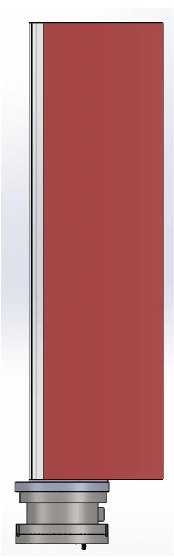
Figure 4.4. Airfoil mounted on the load cell. ... 17
Figure 4.5. Airfoil motion vs time [6]. ... 18
Figure 4.6. Photographs of oscillating mechanism [6]. ... 19
Figure 4.7. Airfoil, load cell and servo motor setup. ... 19
1
CHAPTER 1: Introduction
Rotorcraft are extremely important because of their ability to take off and land without a
runway and hover in place. Because of these abilities, they are often used in specialized tasks like
national defense, fire and rescue and medical transport. While these enhance capabilities make
rotorcraft important, they also complicate the aerodynamics. In order to maintain lift symmetry
in the rotor, the retreating blades need to be at a significantly higher angle of attack than the
advancing blades [1]. Therefore, the blades need to be constantly changing angle of attack as
they rotate around the rotor. After pitching a retreating blade to a higher angle of attack than
the static stall angle, during pitch up or eventual pitch down, the flow can no longer remain
attached to the blades and a phenomenon called dynamic stall can occur.
Dynamic stall occurs in applications where airfoils are rapidly changing angle of attack,
when the change is fast enough, flow over a pitching airfoil remains attached beyond the static
stall angle. This results in the formation of a dynamic stall vortex (DSV) on the leading edge of the
airfoil, which eventually convects over the airfoil and sheds. During DSV convection and the
accompanied flow separation, unsteady aerodynamic loads are produced. These unsteady loads
produce a rapid growth in blade torsion which can lead to fatigue and eventually structural
failure. Due to these issues, dynamic stall is normally the limiting factor in the operational flight
envelope of helicopters [1]. Therefore, in order to increase operating conditions of rotorcraft it
is essential to mitigate the effects of dynamic stall.
Conventionally, research in this field uses passive and occasionally active flow control
devices to mitigate dynamic stall by eliminating the dynamic stall vortex. A common passive
2
because changing the airfoil shape can increase the weight of the blade and change its
aerodynamic properties making it ineffective at off-design operating conditions. Active
techniques include the use of momentum injectors and plasma actuators. Momentum injectors
typically add momentum to the flow via blowing jets [3]. As the speed is increased, more
momentum is needed to sustain control efficacy. This increases the complexity and cost of the
airfoils, but they have the potential to maintain a broad operating range if the required
momentum could be maintained. Plasma actuators, on the hand, are minimally complex and can
still maintain a broad operating range making them ideal for rotorcraft.
Previous research done in the Gas Dynamics and Turbulence Laboratory at Ohio State [4],
has shown promise at mitigating dynamic stall and reattaching the flow over a NACA 0015 airfoil
using a Nanosecond Dielectric Barrier Discharge (NS-DBD) plasma actuator. A high-voltage
nanosecond pulse drives the actuator and creates rapid, localized heating that results in a
thermal perturbation. The thermal perturbation then excites the flow’s natural instabilities and
generates coherent flow structures, which entrain high-momentum free stream air near the
low-momentum airfoil surface, energizing the flow and reducing the chance for separation [5]. The
plasma actuators consist of two copper electrodes separated by a dielectric barrier; they require
a relatively low power input, which allows them to remain effective at high speeds. They are also
less than 0.5mm thick, meaning the aerodynamic properties of the blades are relatively
unchanged [6].
This work aims at improving upon the previous work in the Gas Dynamics and Turbulence
Laboratory at Ohio State [4, 6] by making facility and instrumentation upgrades. This thesis
3
from the previous experimental setup in Chapter 3. Details the shortcomings in the previous
experimental setup and data acquisition and reduction, and steps taken in the current work to
mitigate them in Chapter 4. Finally, concluding remarks and future work are discussed in Chapter
4
CHAPTER 2: Background 2.1 Introduction
Rotorcraft experience dynamic stall because the retreating rotor blades are rapidly
changing angle of attack, therefore the flow over a pitching blade remains attached beyond the
static stall angle. This leads to the formation and shedding of the dynamic stall vortex and
unsteady loads over the blade and ultimately limits the operational flight envelope of the
rotorcraft. To increase the operational capabilities of rotorcraft, the effects of dynamic stall need
to be mitigated. NS-DBD plasma actuators have shown promise at mitigating dynamic stall and
reattaching the flow over a NACA 0015 airfoil, significantly reducing unsteady loads.
2.2 Dynamic Stall
Dynamic stall is characterized in five states, shown below in Figure 2.1 [7]. The first state
occurs when the maximum angle of attack of the airfoil is less than the static stall angle. The
second state occurs when the maximum angle of attack equals the static stall angle, at this point
a leading-edge vortex starts forming. During both of these states, the aerodynamic loads behave
similarly to the static case and the flow is attached. The maximum angle of attack can continue
to increase past the static stall angle because the airfoil pitching motion leads to the formation
of dynamic stall vortex near the leading edge of the airfoil [1]. As the maximum angle of attack
continues to increase past the static stall angle the lift generated by the airfoil also continues to
increases and the leading-edge vortex convects over the airfoil due to the accumulation of
vorticity near the leading edge and sheds, this is the third state. Once the vortex passes the
trailing edge, the airfoil is fully stalled, this is the fourth state. Finally, the fifth state occurs when
5
Figure 2.1. Illustration of dynamic stall [7].
2.3 Flow Control
Conventionally, research in this field uses passive and occasionally active flow
control devices to mitigate dynamic stall by eliminating the dynamic stall vortex. A common
passive technique includes making geometric modifications to the airfoil [2]. This can be
problematic because changing the airfoil shape can increase the weight of the blade and change
6
techniques include the use of momentum injectors and plasma actuators. Momentum injectors
can add momentum to the flow by a variety of techniques including fluidic, piezoelectric,
electromagnetic, and electrostatic [8]. As the flow speed is increased, more momentum is
needed to sustain control efficacy, therefore these techniques become more expensive and less
practical. Overall, momentum injectors increase the complexity and cost of the airfoils, but they
have the potential to maintain a broad operating range if the required momentum could be
maintained. Plasma actuators, on the other hand, are minimally complex, require relatively low
power and can still maintain a broad operating range making them ideal for rotorcraft. The
installation of dielectric barrier discharge (DBD) plasma actuators are relatively simple, as they
are simply placed on the leading edge of airfoil, they minimally effect the flow field when not in
use and they can potentially be retrofitted to existing airfoils. The earliest form of DBD plasma
actuators were alternating current driven (AC-DBD) plasma actuators. AC-DBD plasma actuators
are momentum based, therefore as the speed of the aircraft increases the momentum needed
also increases, but the ion density in the region of the electric charge restricts the momentum
production [8]. Therefore, AC-DBD plasma actuators are currently limited at higher speeds. As a
result, a new driving waveform has been applied to the DBD actuators, nanosecond high voltage
DC pulses, and they are called nanosecond DBD (NS-DBD) plasma actuators. Even though the
physical construction of AC-DBD and NS-DBD are similar, their control mechanisms are very
different because of how they are driven. NS-DBD actuators are thermal based and therefore
7
2.4 NS-DBD
NS-DBD plasma actuators are minimally complex, they consist of two 0.09 mm thick
copper tape electrodes separated by a dielectric layer composed of three layers of 0.09 mm thick
Kapton tape, making the total thickness of the actuator 0.45 mm, shown in Figure 2.2 below.
They are powered by a custom, in-house manufactured pulse generator that sends high-voltage
nanosecond pulses to the copper electrodes, producing the perturbations. The pulse generator
is powered by a 450 VDC power supply [4]. The actuator is placed just downstream of the leading
edge where the shear layer over the airfoil is formed and its natural instability is most receptive
to the perturbations. This reduces the energy consumption of the actuators which on average is,
12.6 mJ per pulse. Overall, the high-voltage nanosecond pulse drives the actuator and creates
rapid, localized heating that results in a thermal perturbation. The thermal perturbation then
excites the flow’s natural instabilities and generates coherent flow structures, which entrain
high-momentum free stream air near the low-momentum airfoil surface, energizing the flow and
reducing the chance for separation [5].
8
CHAPTER 3: Previous Research 3.1 Introduction
A NACA 0015 airfoil was mounted in the recirculating wind tunnel located at the
Aerospace Research Center. The airfoil was connected to an oscillating mechanism that varied
the angle of attack sinusoidally. A plasma actuator was mounted just downstream of the airfoil
leading edge at x/L=0.01. Baseline experiments were done with the plasma actuator installed but
not excited, to understand it’s effect on the flow physics. Experiments were done for three
Reynolds numbers (dimensionless ratio of inertial forces to viscous forces) based on the airfoil
cord (Re=167,000, 300,000 and 500,000), at three reduced frequencies (k=0.025, 0.050, and
0.075) and 20 excitation Strouhal numbers ranging from 0 – 9.9. Detailed unsteady surface
pressure measurements, and flow velocity and turbulence measurements were taken to assess
the effect of control.
3.2 Results
The work resulted in three major conclusions [4]: high Strouhal number excitation results
in small structures and low Strouhal number excitation results in large structures, all excited cases
resulted in earlier flow reattachment, and excited cases had a decreased dynamic stall vortex
strength.
The first finding can be seen in Figures 3.1 and 3.2 below. They show the phase-averaged
swirling strength at a Reynolds number of 300,000 and a reduced frequency of 0.050 while the
airfoil is pitching down from 20 to 17 degrees. Figure 3.1 has an excitation Strouhal number of
0.35, whereas, Figure 3.2 has an excitation Strouhal number of 9.9. In Figure 3.1, a large structure
9
several significantly smaller structures formed over the airfoil and disintegrate while convecting
over the airfoil. While not shown, the large structure convects over the entire airfoil and sheds
from the airfoil leading to oscillatory forces and moments on the blade. As the Strouhal number
increased the oscillatory behavior smooths out. These effects are clearly shown in Figure 3.3 for
the lift and moment coefficients.
10
Figure 3.2. Phase-averaged swirling strength at Re=300,000, k=0.050 and Ste=9.9. Pitching down from 20 to 17 degrees [4].
Figure 3.3. Phase-averaged lift and moment coefficient at Re=300,000 and k=0.050. Darker colors represent pitch up and lighter colors represent pitch down. [4]
11
The next conclusion, all excited cases resulted in earlier flow reattachment, is shown
below in Figure 3.4. The baseline reattachment angle of attack was 7.2 degrees. Exciting the flow
with a Strouhal number of 0.35 produced the largest differential increase in the reattachment
angle jumping from 7.2 to 8.5 degrees. As the Strouhal number continued to increase, it produced
a general upward trend of reattaching the flow earlier; overall, every excited case reattached the
flow earlier than the baseline test.
Figure 3.4. Reattachment angle of attack versus the excitation Strouhal number at Re=300,000 and k=0.050 [4].
The final conclusion, excited cases had a decreased dynamic stall vortex, is shown below
in Figure 3.5. Due to the poor temporal resolution in the PIV data, the strength of the dynamic
stall vortex could not be directly determined, but a normalized reduction in moment coefficient
12
Strouhal number increases the normalized reduction in baseline moment coefficient peak
increases. This means the magnitude of the peak moment coefficient is decreasing. Once it
plateaus, it means the dynamic stall vortex is suppressed. At a Reynolds number of 176,000 and
a reduced frequency, the dynamic stall vortex is suppressed at an excitation Strouhal number of
eight.
Figure 3.5. Normalized reduction in baseline moment coefficient peak versus excitation Strouhal number at Re=176,000 and k=0.05 [4].
Overall, this research shows high Strouhal number excitation results in small
structures that quickly develop, breakdown, and result in smooth, partial reattachment of the
flow, whereas low Strouhal number excitation results in large structures that are capable of fully
13
CHAPTER 4: Shortcomings of Previous System and Their Mitigation 4.1 Introduction
Based on the previous research, NS-DBD plasma actuators show promise at suppressing
dynamic stall and reattaching the flow over a NACA 0015 airfoil, significantly reducing unsteady
loads. Due to design of the facility and the instrumentation used, there are some shortcomings
in the repeatability, generating significant uncertainties in the collected data. The results are also
not directly relatable to rotorcraft due to the type of airfoil used. The following sections will go
over each of the shortcomings and the solution to address them.
4.2 Airfoil
A NACA 0015 airfoil is characterized as a thick airfoil because its maximum thickness to
chord ratio is 15 percent. Thick airfoils experience trailing edge stall. Rotorcraft, on the other
hand, typically use thin airfoils and thin airfoils experience leading edge stall. Therefore, the
previous results cannot be directly related to rotorcraft because the airfoil tested experiences a
different type of flow separation. As a result, a NACA 0012 airfoil was manufactured for future
experiments. It is a thin, symmetric airfoil with a maximum thickness to chord ratio of 12 percent.
This specific airfoil was chosen because it is well characterized in literature.
Another concern with the previous airfoil was its size creating too much blockage in the
wind tunnel and potentially skewing the results. The static coefficient of lift versus angle of attack
for the previous setup and results from literature are shown below in Figure 4.1. They both show
that the static stall angle is 13 degrees, but the airfoil used in the previous study has a much
sharper stall. The NACA 0015 airfoil has a chord of 8 in. therefore the new NACA 0012 airfoil was
14
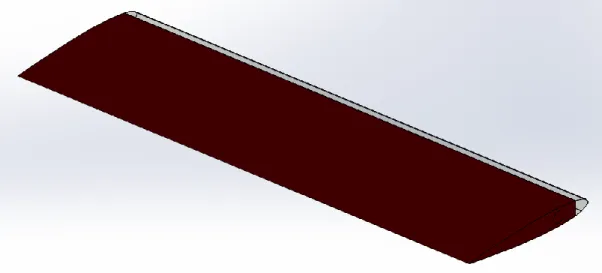
to install the plasma actuators on, shown in Figure 4.2 below. This was done to prevent arcing
between the high voltage plasma actuators and the metal airfoil. The material Delrin was chosen
because it a synthetic polymer with a high stiffness. In the event that the leading edge does get
damaged, it can easily be replaced.
15
Figure 4.2. NACA 0012 airfoil with a replaceable Delrin leading edge.
4.3 Force and Moment Measurements
In the previous setup, 35 static pressure taps were located on the surface of the airfoil in
order to calculate the phase-averaged pressure coefficient, Figure 4.3. From these pressure
measurements the lift, drag and moment were calculated. Due to the long pressure tap lines
from the airfoil to the data acquisition system, empirical lag/gain corrections were applied to the
data. Overall, this system of calculating the lift, drag and moment introduced error due to the
potential three-dimensionality in the flow. Therefore, the new system directly measures the lift,
drag and moment using an ATI SI-660-60 6-axis force/torque transducer with great resolution,
16
Figure 4.3. Static pressure tap distribution [6]. Table 1. Load cell sensing range and resolution.
Sensing Range Resolution
Fx 660 N 1/8 N Fy 660 N 1/8 N Fz 1980 N 1/4 N Tx 60 Nm 10/1333 Nm Ty 60 Nm 10/1333 Nm Tz 60 Nm 10/1333 Nm
17
Figure 4.4. Airfoil mounted on the load cell.
4.4 Servo-Optical Access
For dynamic stall experiments, the airfoil needs to be consistently changing angle of
attack to simulate flight conditions; to do this the previous setup used a servomotor driven by
timing belts. There are two main concerns with the previous setup, first the timing belts can
stretch over time creating a phase delay and second the overall setup reduced the optical access.
The cycle-to-cycle motion of the servo is shown below in Figure 4.5, it was oscillated
sinusoidally from 8 to 18 degrees at a frequency of 3.48 Hz. The individual cycles varied up to a
18
repeatability standpoint, if the actual motion of the airfoil is unknown, the actual stall
characteristics are also unknown. This can be attributed to the timing belts, over time they tend
to stretch or slip. To counteract this, the new setup uses a direct drive servo that is accurate to a
thousandth of a degree.
Figure 4.5. Airfoil motion vs time [6].
To secure the airfoil in the wind tunnel, its ends were connected to disks in the sidewall
of the wind tunnel. The disks were then driven by the servomotor-timing belt combination,
shown below in Figure 4.6. The disks in the sidewall of the wind tunnel obstructs the view near
the trailing edge of the airfoil in Particle Image Velocimetry (PIV) measurements, therefore the
vortex shedding over the trailing edge is obstructed, an example of this is shown in Figures 3.1
and 3.2. PIV is a major optical measurement tool in obtaining detailed flow velocity and
turbulence measurements. If the setup obstructs optical access to the model, it makes the tool
significantly less useful in exploring flow physics. For that reason, the direct drive servomotor is
19
vertically on top of them, therefore there will be no obstructions in the optical access, shown in
Figures 4.7 and 4.8.
Figure 4.6. Photographs of oscillating mechanism [6].
20
Figure 4.8. Full setup mounted in the wind tunnel.
4.5 Control System
To control the system and collect data three data systems were used, these include a
National Instrument Data Acquisition (NI-DAQ) system, three Scanivalve Pressure Scanners (SPS),
and an ABB Servo Controller. To synchronize the NI-DAQ and the SPS a continuous chirp signal
was used. The chirp was transmitted to the NI-DAQ using LabVIEW and it was transmitted to the
SPS using a speaker. The constant lag between the inputs and outputs were determined and
21
achieved by aligning the analog output of the servo to the position given by the network
connection.
Having three data acquisition systems can introduce synchronization errors, which is
extremely detrimental to dynamic stall tests since dynamic stall is time dependent. Therefore,
the new system uses a NI-CompactRIO (CRIO). It has a real-time processor, a user-programmable
FPGA, and interchangeable modules for each instrument, this ensure complete synchronization
22
CHAPTER 5: Conclusions and Future Work
Dynamic stall occurs in applications where airfoils are rapidly changing angle of attack.
When the change is fast enough, flow over a pitching airfoil remains attached beyond the static
stall angle. This results in the formation of a dynamic stall vortex (DSV) on the leading edge of the
airfoil, which eventually convects over the airfoil and sheds. During DSV convection and the
accompanied flow separation, unsteady aerodynamic loads are produced. These unsteady loads
produce a rapid growth in blade torsion which can lead to fatigue and eventually structural
failure. Due to these issues, dynamic stall is normally the limiting factor in the operational flight
envelope of helicopters. Therefore, in order to increase operating conditions of rotorcraft it is
essential to mitigate the effects of dynamic stall. Previous research has shown promise at
mitigating dynamic stall and reattaching the flow over a NACA 0015 airfoil using a NS-DBD plasma
actuator. This work aims at improving upon the previous work by changing the airfoil to a NACA
0012 to make it more relevant to rotorcraft, using a load cell to directly measure the forces and
moments on the airfoil, changing to a direct-drive servo to mitigate the cycle-to-cycle motion
variation, and incorporating all systems into one control system to ensure complete
synchronization.
Future work includes detailed unsteady lift, drag, and moment and flow velocity and
turbulence measurements, at the same parameters tested with the old setup but with the new
experimental setup. This is to verify that the same trends are seen and that they can be applied
to rotorcraft, by using the thin airfoil. Additional excitation Strouhal numbers will be tested to
determine if there is an optimum value. Due to the upgraded system, higher excitation Strouhal
23
to see the dynamic stall vortex and the subsequent excitation structures; this will greatly improve
the understanding of the flow physics. Overall, this research is being conducted to mitigate the
negative effects of dynamic stall, which has the potential to increase the lifespan of the blades
24
CHAPTER 6: References
[1] J. G. Leishman, Principles of Helicopter Aerodynamics, 2 ed., Cambridge: Cambridge University Press, 2006.
[2] W. Joo, B. Lee, K. Yee, and D. Lee, "Combining Passive Control Method for Dynamic Stall Control," Journal of Aircraft, Vol. 43, No. 4, pp. 1120-1128, 2006.
[3] D. Weaver, K. W. McAlister and J. Tso, "Suppression of Dynamic Stall by Steady and Pulsed Upper-Surface Blowing," NASA, Moffett Field, 1996.
[4] A. Singhal, D. Castaneda, N. Webb, and M. Samimy, “Control of Dynamic Stall over a NACA 0015 Airfoil using NS-DBD Plasma Actuators,” AIAA Journal, Vol. 56, No. 1, pp. 78-89, 2018. [5] J. Little, K. Takashima, M. Nishihara, I. Adamovich, and M. Samimy, “Separation Control with Nanosecond Pulse Driven Dielectric Barrier Discharge Plasma Actuators,” AIAA Journal, Vol. 50, pp. 350-365, 2012.
[6] A. Singhal, "Unsteady Flow Separation Control over a NACA 0015 using NS-DBD Plasma Actuators," M.S. Thesis, Department of Mechanical and Aerospace Engineering, The Ohio State University, Columbus, 2016.
[7] T. C. Corke and F. O. Thomas, "Dynamic Stall in Pitching Airfoils: Aerodynamic Damping and Compressibility Effects," Annual Review of Fluid Mechanics, pp. 479- 505, 2015.
[8] C. Rethmel, J. Little, K. Takashima, M. Nishihara, I. Adamovich, and M. Samimy, “Flow
Separation Control over and Airfoil with Nanosecond Pulse Driven DBD Plasma Actuators,” International Journal of Flow Control, Vol. 3, No. 4, pp. 213-232, 2011.
![Figure 2.1. Illustration of dynamic stall [7].](https://thumb-us.123doks.com/thumbv2/123dok_us/1877156.2774055/11.918.116.802.110.756/figure-illustration-of-dynamic-stall.webp)
![Figure 2.2. NS-DBD plasma actuator schematic [4]. Thickness is exaggerated for clarity](https://thumb-us.123doks.com/thumbv2/123dok_us/1877156.2774055/13.918.125.796.739.899/figure-dbd-plasma-actuator-schematic-thickness-exaggerated-clarity.webp)
![Figure 3.1. Phase-averaged swirling strength at Re=300,000, k=0.050 and St e =0.35. Pitching down from 20 to 17 degrees [4]](https://thumb-us.123doks.com/thumbv2/123dok_us/1877156.2774055/15.918.140.776.357.774/figure-phase-averaged-swirling-strength-st-pitching-degrees.webp)
![Figure 3.2. Phase-averaged swirling strength at Re=300,000, k=0.050 and St e =9.9. Pitching down from 20 to 17 degrees [4].](https://thumb-us.123doks.com/thumbv2/123dok_us/1877156.2774055/16.918.138.782.116.537/figure-phase-averaged-swirling-strength-st-pitching-degrees.webp)
![Figure 3.4. Reattachment angle of attack versus the excitation Strouhal number at Re=300,000 and k=0.050 [4]](https://thumb-us.123doks.com/thumbv2/123dok_us/1877156.2774055/17.918.234.675.385.841/figure-reattachment-angle-attack-versus-excitation-strouhal-number.webp)
![Figure 3.5. Normalized reduction in baseline moment coefficient peak versus excitation Strouhal number at Re=176,000 and k=0.05 [4].](https://thumb-us.123doks.com/thumbv2/123dok_us/1877156.2774055/18.918.212.706.344.694/figure-normalized-reduction-baseline-moment-coefficient-excitation-strouhal.webp)
![Figure 4.1. Static coefficient of lift vs angle of attack [6].](https://thumb-us.123doks.com/thumbv2/123dok_us/1877156.2774055/20.918.228.689.313.793/figure-static-coefficient-lift-vs-angle-attack.webp)
![Figure 4.3. Static pressure tap distribution [6].](https://thumb-us.123doks.com/thumbv2/123dok_us/1877156.2774055/22.918.117.778.135.354/figure-static-pressure-tap-distribution.webp)