Procedia Engineering 90 ( 2014 ) 232 – 237
1877-7058 © 2014 The Authors. Published by Elsevier Ltd. This is an open access article under the CC BY-NC-ND license (http://creativecommons.org/licenses/by-nc-nd/3.0/).
Selection and peer-review under responsibility of the Department of Mechanical Engineering, Bangladesh University of Engineering and Technology (BUET)
doi: 10.1016/j.proeng.2014.11.842
ScienceDirect
10th International Conference on Mechanical Engineering, ICME 2013
Flow Separation Control Using Plasma Vortex Generator
A.N.M. Mominul Islam Mukut
a,*, Hiroshi Mizunuma
b, Obara Hiromichi
b aDhaka University of Engineering & Technology (DUET), Gazipur-1700, BangladeshbTokyo Metropolitan University, Tokyo 192-0397, Japan
Abstract This paper represents a series of experiment to figure out plasma vortex generator as a means of separation flow control. Typical conventional vortex generator is a vane normal to wall and has a yaw angle against a main flow. This yaw angle gives a penalty of drag increase at the sacrifice of the separation suppression. A plasma vortex generator developed here has a yaw angle of 0° and thus the penalty could be minimized. An exposed electrode was installed on the Kapton vane tip, and another electrode was embedded in the vane. Stream-wise counter-rotating vortices are produced by the vane type plasma vortex generator at downstream that helps to control flow separation. The effect of the plasma vortex generator has been investigated on a turbulent boundary layer on a 20°-inclined slope. The separation flow was visualized by using a smoke wire, and the velocity profiles were measured using a hot-wire anemometer. The plasma vortex generators suppressed the separation similarly as the conventional vortex generator, and its performance was validated.
© 2014 The Authors. Published by Elsevier Ltd.
Selection and peer-review under responsibility of the Department of Mechanical Engineering, Bangladesh University of Engineering and Technology (BUET).
Keywords: Plasma actuator; vortex generator; flow control; separation; velocity profile; smoke wire; hot wire.
1.Introduction
Control of flow separation is a flow phenomenon with great practical importance that has been extensively
investigated. In a turbulent flow, Schubauer and Spangenberg [1] investigated various mixing devices to control the separation-among them the most effective is vortex generator (VG). Vortex generators (here after VG) create stream-wise vortices close to the surface with which they are attached. The mixing between boundary layer and free stream is increased due to the formation of vortices which bring momentum to the near wall region. Hence near wall flow become energies to withstand more adverse pressure gradient and flow separation become delayed, even
* Corresponding author. Tel.: +8801913471401; fax: +88-02-9204710.
E-mail address: [email protected]
© 2014 The Authors. Published by Elsevier Ltd. This is an open access article under the CC BY-NC-ND license (http://creativecommons.org/licenses/by-nc-nd/3.0/).
Selection and peer-review under responsibility of the Department of Mechanical Engineering, Bangladesh University of Engineering and Technology (BUET)
completely avoided. Various type of VGs have been investigated by researchers such as rectangular vanes by Lin [2]; doublets & wishbone by Lin et al. [3]; trapezoid vanes & delta vanes by Lin et al. [4], Melin et al. [5], Culter et al. [6], Satta et al. [7] and DavideLengani et al. [8]; triangular vanes by Velte et al. [9]; cylinder by Thomas et al., [10]. All of these VGs have advantage and disadvantage over each other depending on size, shape, flow condition and the body with which they are attached. Rectangular vanes types VGs are most widely used as they are simple in shape, cheaper, easy to manufacture and can be fitted easily to the surface. The conventional vane-type VG has a height of the order of the boundary layer thickness, and has a penalty of drag increase. This penalty is critical, if the separation control is limited to short time. In order to minimize the drag penalty, smaller VGs submerged in the boundary layer were developed, as reviewed by Lin [11]. Plasma actuator is the new alternative without the drag penalty to control the separation. Very recently, Juke and Choi [12] extended the plasma actuator to induce stream-wise counter-rotating or co-rotating vortices like VGs. On the other hand, the authors [13] have developed a winglet-type plasma actuator and characterized the jet flow induced from the winglet. The jet flow is induced from the exposed electrode over the covered electrode. In this study, winglet-type plasma actuator is acted like vane type VG and called as plasma vortex generator (here after PVG). The plasma induced flow from the vane tip to the hub produces a pair of stream-wise counter-rotating vortices downstream. A yaw angle of the vane is zero against a main flow, and thus the drag penalty is expected to be low if the plasma is switched off. The effect of the separation suppression was validated and compared with that of the conventional VGs.
Nomenclature
h height of VG/PVG in mm
l length of VG/PVG in mm
d span-wise spacing of VG/PVG in mm
ΔxVG Stream-wise distance from line of separation in mm
2. Method
2.1.Experimental setup and measurement methodology
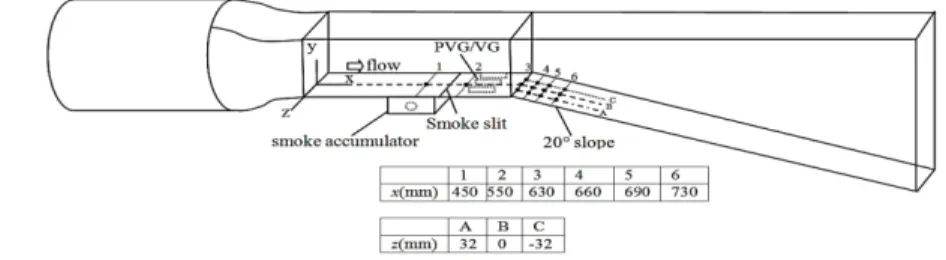
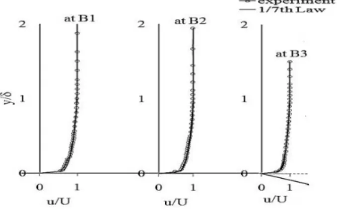
The experiment was carried out in an open type wind tunnel composed of a straight entrance section and a diffuser section. The coordinate system of x, y, and z was defined as shown in Fig. 1. The x-wise lengths of these sections were 0.63m and 1.4m, respectively. The cross section of the entrance was 0.2 m by 0.2 m. A tripping wire of 2 mm diameter was fixed at x = 50 mm in the straight entrance section to develop a turbulent boundary layer. To confirm the development of turbulent boundary layer velocity profile measured in some stream-wise locations and compare with 1/7th law [14] and it is found that in rectangular section of wind tunnel the comparison are well match which is represented in Fig.2. The bottom wall of the diffuser section was inclined by 20 degree against the horizontal x-coordinate. Flow separation on the inclined slope was measured by using hot wire anemometer and flow visualization. The overall flow behavior on the slope was observed using a smoke sheet fed through the wall slit.
Fig. 1. Schematic of wind tunnel (not to scale)
The smoke was fed from a generator (SLN-200, Nissho Electric Work Co. Ltd, Tokyo) to a smoke accumulator box, which made the smoke sheet stable and uniform. The visualization of a local velocity profile was carried out using a smoke wire of 0.2 mm diameter. The smoke wire passed through the acrylic wall, and was thermally
insulated with cement at the wall hole. The smoke wire was coated with Paraffin oil and a pulse of high voltage was applied to the wire using a pulse generator (MS-405, Sugawara, Tokyo). The smoke flow was recorded with a high speed video camera (MEMRICAM GX-1, NAC Image Technology, Tokyo).
Fig. 2. Comparison of measured velocity profile with 1/7th law
The trigger sent signals to the electric pulse generator and the video camera were controlled by a microcomputer (Uno, Arduino, Italy). Velocity profiles were measured using a hot wire anemometer (Kanomax, Osaka). A single-wire probe was attached to a traversing unit equipped with digital slide calipers. The output of the anemometer was recorded in a PC via an A/D processing unit (Yokogawa Electric Corp., Tokyo). Free stream velocity was fixed to 4 m/s in this study.
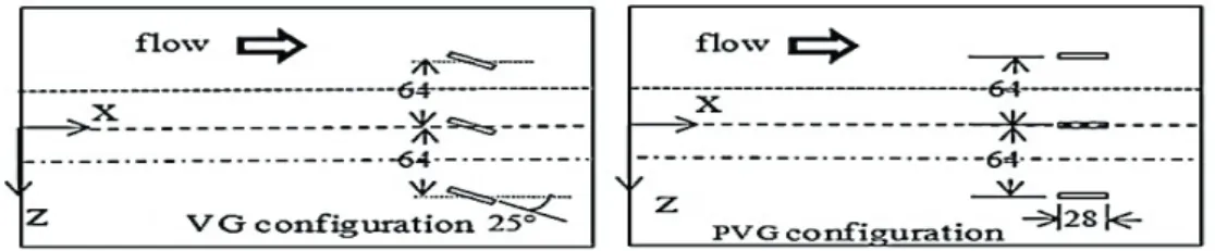
2.2 Configurations of VG and PVG
The conventional VG used here was a vane-type and its height was designed to submerge in the boundary layer thickness. Dimensions have been characterized from Lin [2]. The yaw angle between the flow and the VG was fixed to 25 degree. Table 1 shows the dimension of the VG in mm. The same dimensions were applied to the PVG, but the yaw angle was fixed to zero. This stream-wise alignment enables to minimize the drag penalty under the non-plasma, that is, non-vortex operation.
Table 1. Dimension of VG and PVG
Parameters Size (mm) h 7 l 28 d 64 ΔxVG 70
Three VGs were installed on the wall of the entrance straight section. The PVG has an exposed electrode of 2 mm width on the each side and a covered electrode of 5 mm width, as shown in Fig. 3. Kapton film was used as the dielectric material. AC pulses of 4 kV and 5 kHz was applied to the exposed electrode using an electric power supply (PSI-PG1040F, KITECH, Tokyo).
x=630mm
at B4
at B5
at B6
Fig. 3. Schematics of (a) plasma vortex generator (PVG) and (b) the configurations of VGs/PVGs in the entrance straight section. All dimensions are shown in mm
3. Result and Discussions
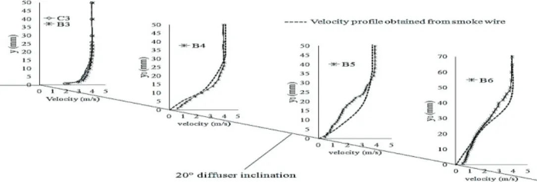
The smoke sheet was fed from the wall slit showed that the separation point located at x = 640 mm, which was 10 mm downstream from the start of the diffuser section. At the same time, the visualization by a smoke wire showed the flow separation on the slope, as shown in Fig. 4(a). The velocity profiles obtained from a hot wire anemometer were plotted in Fig. 4(b). A hot wire anemometer cannot discriminate the flow direction, and thus the velocity plotted shows the absolute value including reverse flow. A boundary layer thickness δ was defined as the height where the velocity reached 0.99U, and the thickness obtained were 16 mm, 19 mm, 20 mm, 30 mm, 43 mm and 55 mm at x = 450 mm, 550 mm, 630 mm, 660 mm, 690 mm, and 730 mm, respectively.
The flow separation was suppressed by the plasma and conventional VGs as shown by the smoke wire pictures of Fig. 5. The span-wise location of the smoke wire was fixed on the middle line B in Fig. 1. The velocity in the boundary layer decelerated downstream, but the flow separation was suppressed at least along the line B, as shown in Fig. 4.
(a) Visualization by a smoke wire. (b) Time averaged velocity profiles obtained from a hot wire anemometer. Fig. 4. Flow separation under no actuation by vortex generators. The pictures in (a) were taken at 10ms after a high voltage pulse was loaded into
the smoke wire.
(a) Plasma vortex generators. (b) Conventional vortex generators.
Fig. 5. Visualization by a smoke wire. The plasma vortex generators (a) and the conventional vortex generators (b) suppressed the flow separation. The span-wise location of the wire was fixed along the line B. These pictures were taken at 10ms after a high voltage pulse was
The hot wire anemometer cannot discriminate the flow direction, but the velocity profiles along the line B approximately agreed with the smoke wire results, as shown in Figs. 6 and 7. The induced stream-wise vortices are span-wisely symmetric in the case of PVG.
By contrast, the conventional VG has a yaw angle against the main flow, and thus the induced stream-wise vortex has a yaw angle. The velocity profiles along the line A shows remarkable deceleration as Fig.4 (b), and the velocity profiles along the lines B and C shows the profiles similar as PVG.
Fig. 6. Time averaged velocity profiles obtained under the operation of plasma vortex generators. The velocity profiles show gradual deceleration downstream.
Fig. 7. Time averaged velocity profiles obtained using the conventional vortex generators. The results were dependent on the span-wise location, but the results along the middle line B approximately agreed with the results of the smoke wire.
Fig. 8. Comparison of time averaged velocity profiles obtained from Fig. 9. Turbulence intensity at various measuring locations PVG [OFF] and no vortex conditions to investigate drag penalty-at B4
The plasma vortex actuator does not have a yaw angle against a main flow, and thus the penalty of drag increase is expected to be low when the plasma is switched off. When the plasma is switched off, the flow returned to the separation flow as shown in Fig. 8. This result showed the advantage of PVG over convectional VG that PVG can be switched off to minimize the drag penalty when it is not necessary to control the flow.
Fig. 9 represent the turbulence intensity (TI) at each measuring location through line B [see figure 1] which is defined as the ratio of std. deviation and corresponding velocity at each point. It is found that turbulence intensity is almost zero in free stream region.
4. Conclusion
In this experimental investigation it is found that plasma vortex generator can produce stream wise vortices and enhance the mixing between boundary layer and outer free stream flow which suppress the flow separation. The suppression effect is comparable with the conventional vortex generators in a turbulent boundary layer flow. A hot wire anemometer cannot discriminate the flow direction hence the velocity plotted shows the absolute value including reverse flow. Smoke wire visualization has been carried out to figure out the velocity profile, it is found that the velocity profiles obtained from hot wire anemometer along the line B approximately agreed with the smoke wire results. Furthermore, plasma vortex generator can be switched OFF and ON according to the requirement of flow control and it is found that when plasma vortex generator is switched OFF there is no change in original separated flow condition. As a result drag penalty is minimized but it is not possible with convectional vortex generators. Plasma vortex generator would be a better means of flow control device in the field of flow control engineering considering above mentioned criteria and comparison with convectional vortex generator.
References
[1] G. Schubauer, W. Spangenberg, Forced mixing in boundary layers, J. Fluid Mech. (1960) 10-32.
[2] J. C. Lin, Control of turbulent boundary layer separation using micro vortex generator, 30th AIAA Fluid Dynamics Conference, Norfolk, VA (1999).
[3] J. C. Lin and F. G. Howard, Small submerged vortex generator for turbulent flow separation control, J. spacecraft, 27 (1990).
[4] J.C. Lin, S. K. Robinson , R. J. McGhee and W. Valarezo, Separation control on high-lift airfoils via micro-vortex generator, J. Aircraft, 31 (1994).
[5] T. Melin, S. Crippa, M. Holly and M. Smidy, Investigating active vortex generators as a novel high lift device, 25th international congress of the aeronautical sciences (ICAS 2006), Hamburg, Germany
[6] A. D. Culter, P. Bradshaw, Strong vortex/boundary layer interactions Part II. Vortices flow, Experiments in fluids, (1993) 393-401. [7] F. Satta, D. Simoni, M. Ubaldi, P. Zunino, Velocity and turbulence measurements in a separating boundary layer with laser Doppler
velocimetry, Proceeding of ImechE, Part A: J. Power and Energy
[8] D. Lengani, D. Simoni, M. Ubaldi., P. Zunino and F. Bertini, Turbulent boundary layer separation control and loss evaluation of low profile vortex generators, Experimental Thermal and Fluid Science
[9] C.M.Velte, M. Hansen and K. Jonck, Experimental and numerical investigation of the performance of vortex generators on separation control, Journal of Physics: Conference Series 75 (2007).
[10] T. Duriez., J. Aider and J.E.Wesfreid, Base flow modification by streamwise vortices. Application to the control of separated flows, ASME Joint U.S. - European Fluids Engineering Summer Meeting (2006).
[11] J.C. Lin, Review of research on low-profile vortex generators to control boundary-layer separation, Prog. Aerosp. Sci. (2002), 389–420. [12] T. N. Jukes, K.-S Choi., Dielectric-barrier-discharge vortex generators: characterisation and optimisation for flow separation control,
Experiments in Fluids, (2012),329-345.
[13] A. N. M. Mominul Islam Mukut, H. Mizunuma, T. Segawa, H. Obara, PIV measurements of flow characteristics induced by mini plate- wing plasma actuator, 63th Annual DFD Meeting (2010).