NASA/TM—2009-215615
AIAA–2009–193
Wind-US Code Physical Modeling Improvements to
Complement Hypersonic Testing and Evaluation
Nicholas J. Georgiadis, Dennis A. Yoder, and Charles S. Towne
Glenn Research Center, Cleveland, Ohio
William A. Engblom and Vishal A. Bhagwandin
Embry Riddle Aeronautical University, Daytona Beach, Florida
Greg D. Power and Dennis W. Lankford
U.S. Air Force Arnold Engineering Development Center, Arnold Air Force Base, Tennessee
Christopher C. Nelson
Innovative Technologies Applications Company, LLC, Chester
Þeld, Missouri
NASA STI Program . . . in Profile
Since its founding, NASA has been dedicated to the advancement of aeronautics and space science. The NASA Scientific and Technical Information (STI) program plays a key part in helping NASA maintain this important role.
The NASA STI Program operates under the auspices of the Agency Chief Information Officer. It collects, organizes, provides for archiving, and disseminates NASA’s STI. The NASA STI program provides access to the NASA Aeronautics and Space Database and its public interface, the NASA Technical Reports Server, thus providing one of the largest collections of aeronautical and space science STI in the world. Results are published in both non-NASA channels and by NASA in the NASA STI Report Series, which includes the following report types:
TECHNICAL PUBLICATION. Reports of completed research or a major significant phase of research that present the results of NASA programs and include extensive data or theoretical analysis. Includes compilations of significant scientific and technical data and information deemed to be of continuing reference value. NASA counterpart of peer-reviewed formal professional papers but has less stringent limitations on manuscript length and extent of graphic presentations.
• TECHNICAL MEMORANDUM. Scientific and technical findings that are preliminary or of specialized interest, e.g., quick release reports, working papers, and bibliographies that contain minimal annotation. Does not contain extensive analysis.
• CONTRACTOR REPORT. Scientific and technical findings by NASA-sponsored contractors and grantees.
• CONFERENCE PUBLICATION. Collected papers from scientific and technical
conferences, symposia, seminars, or other meetings sponsored or cosponsored by NASA. • SPECIAL PUBLICATION. Scientific,
technical, or historical information from NASA programs, projects, and missions, often concerned with subjects having substantial public interest.
• TECHNICAL TRANSLATION. English-language translations of foreign scientific and technical material pertinent to NASA’s mission. Specialized services also include creating custom thesauri, building customized databases, organizing and publishing research results.
For more information about the NASA STI program, see the following:
• Access the NASA STI program home page at
http://www.sti.nasa.gov
• E-mail your question via the Internet to help@ sti.nasa.gov
• Fax your question to the NASA STI Help Desk at 443–757–5803
• Telephone the NASA STI Help Desk at 443–757–5802
• Write to:
NASA Center for AeroSpace Information (CASI)
7115 Standard Drive Hanover, MD 21076–1320
NASA/TM—2009-215615
AIAA–2009–193
Wind-US Code Physical Modeling Improvements to
Complement Hypersonic Testing and Evaluation
Nicholas J. Georgiadis, Dennis A. Yoder, and Charles S. Towne
Glenn Research Center, Cleveland, Ohio
William A. Engblom and Vishal A. Bhagwandin
Embry Riddle Aeronautical University, Daytona Beach, Florida
Greg D. Power and Dennis W. Lankford
U.S. Air Force Arnold Engineering Development Center, Arnold Air Force Base, Tennessee
Christopher C. Nelson
Innovative Technologies Applications Company, LLC, Chester
Þeld, Missouri
Prepared for the
47th Aerospace Sciences Meeting
sponsored by the American Institute of Aeronautics and Astronautics
Orlando, Florida, January 5–8, 2009
National Aeronautics and
Space Administration
Glenn Research Center
Cleveland, Ohio 44135
Acknowledgments
This work is jointly sponsored by the Department of Defense Test Resource Management Center (DTRMC) Test and Evaluation/ Science and Technology (T&E/S&T) Program and the NASA Fundamental Aeronautics Hypersonics Project. The contributions
of other individuals to this work not listed as authors on this report are also acknowledged: Nicholas A. Denissen, Texas A&M University, Bruno Fletcher, CFD Research Corporation, Michael R. O’Gara, Combustion Research
and Flow Technology, Inc., and Joo Suh, Raytheon Corporation.
This work was sponsored by the Fundamental Aeronautics Program at the NASA Glenn Research Center.
Level of Review: This material has been technically reviewed by technical management.
Available from
NASA Center for Aerospace Information National Technical Information Service
7115 Standard Drive 5285 Port Royal Road
Wind-US Code Physical Modeling Improvements to
Complement Hypersonic Testing and Evaluation
Nicholas J. Georgiadis, Dennis A. Yoder, and Charles S. Towne National Aeronautics and Space Administration
Glenn Research Center Cleveland, Ohio 44135
William A. Engblom and Vishal A. Bhagwandin Embry Riddle Aeronautical University
Daytona Beach, Florida 32114 Greg D. Power and Dennis W. Lankford U.S. Air Force Arnold Engineering Development Center
Arnold Air Force Base, Tennessee 37388 Christopher C. Nelson
Innovative Technologies Applications Company, LLC Chesterfield, Missouri 63006
This report gives an overview of physical modeling enhancements to the Wind-US flow solver which were made to improve the capabilities for simulation of hypersonic flows and the reliability of computations to complement hypersonic testing. The improvements include advanced turbulence models, a bypass transition model, a conjugate (or closely coupled to vehicle structure) conduction-convection heat transfer capability, and an up-graded high-speed combustion solver. A Mach 5 shock-wave boundary layer interaction problem is used to investigate the benefits of k – e and k – w based explicit algebraic stress turbulence models relative to linear two-equation models. The bypass transition model is validated using data from experiments for incompressible boundary layers and a Mach 7.9 cone flow. The conjugate heat transfer method is validated for a test case involving reacting H2 – O2 rocket exhaust over cooled calorimeter panels. A dual-mode scramjet configuration
is investigated using both a simplified 1-step kinetics mechanism and an 8-step mechanism. Additionally, variations in the turbulent Prandtl and Schmidt numbers are considered for this scramjet configuration.
Nomenclature Cf skin friction coefficient
h static enthalpy
H fuel injector ramp height for scramjet test case
k turbulent kinetic energy
M Mach number
P static pressure
Pk production of turbulent kinetic energy qw˙ rate of wall heat flux
Ret turbulent Reynolds number = Pk/µW
Re., plate Reynolds number
Re/m unit Reynolds number for hypersonic cone flow case
Re„ vorticity-based Reynolds number = Py2Q/µ St Stanton number
t time
T static temperature
T0 stagnation temperature T. wall static temperature
Ui velocity
U. freestream velocity
x, y, z Cartesian coordinates
y+ wall normal coordinate
µ dynamic viscosity
µt dynamic eddy viscosity
W specific turbulent dissipation rate Q vorticity magnitude
P density
Poo freestream density
Introduction
Investment in hypersonic research and development (R&D) has been cyclical over the past several decades. Most recently, there is renewed interest in the United States, with both the Department of Defense (DoD) and the National Aeronautics and Space Administration (NASA) pursuing hypersonic technology development. In subsonic and supersonic aeronautics R&D programs, computational fluid dynamics (CFD), ground testing, and flight testing (where resources permit) have been used successfully in concert to make greater gains than could be obtained by each method alone.
Many years ago, CFD was envisioned in an overly optimistic manner as eventually eliminating the need for wind tunnel and flight testing. Instead of this unrealistic goal, CFD has evolved to become an important complement to testing and now serves many roles critical to successful R&D projects and optimal use of experimental testing, including: (1) pre-test screening of R&D concepts to reduce large test matrices, (2) identification of potential operational problems that would delay testing or adversely affect test safety and facility integrity, (3) determination of proper test article placement, (4) correction or elimination of test artifacts, (5) independent validation of test data via computations, (6) on-line test decision making through real time data-CFD comparisons, (7) sizing and location of instrumentation, (8) explanation of test data anomalies, and (9) extension and enhancement of experimental results. For this last role of extending and enhancing experimental results, CFD offers many advantages over testing alone. CFD can provide great insight into test data by providing the equivalent of probes at, in many cases, millions of physical locations (equal to the number of grid points used). CFD enables analysis of operating conditions between test points and thereby enables substantial savings in wind tunnel test time and expenditures. Further, CFD can provide insight into Reynolds number and other scaling effects to extrapolate wind tunnel model results to production scale.
While CFD methods have been used successfully in support of subsonic and low supersonic R&D pro-grams, there are several aspects of hypersonic flow modeling for which CFD methods are still far from mature, especially in the area of physical modeling. As a result, advancement of CFD methods to comple-ment expericomple-mental testing using proven and validated state-of-the-art flow solver technologies is desirable and the focus of this work.
The approach taken is to develop and demonstrate a state-of-the-art CFD solver that has the capability to conduct high-fidelity simulations of hypersonic vehicles incorporating integration of the entire propulsion system flow path. To accomplish this, code technology enhancements in the area of physical modeling have been made to a proven CFD tool, Wind-US, that has the necessary existing framework and a broad user base in the U.S. aerospace community including government, industry, and academia. Wind-US is the production Reynolds Averaged Navier-Stokes (RANS) solver of the NPARC Alliance, a formal partnership
of NASA Glenn Research Center (GRC) and the U.S. Air Force Arnold Engineering Development Center (AEDC), with significant participation by the Boeing Company.1 For over a decade, the NPARC Alliance’s
computational tools, now centered upon the Wind-US flow solver, have been used very effectively in concert with experimental testing to enable many successful (R&D) efforts. At AEDC and NASA GRC, Wind-US has been one of the primary CFD tools serving in this role.
This report describes work sponsored by the Office of the Secretary of Defense (OSD) Test and Eval-uation/Science and Technology (T&E/S&T) Program and the NASA Fundamental Aeronautics Program to incorporate physical modeling enhancements to the Wind-US flow solver which improve the capabilities for simulation of hypersonic flows. The improvements include addition of advanced high-speed combustion modeling capabilities, advanced turbulence models, laminar to turbulent boundary layer transition modeling, and a conjugate (or closely coupled to vehicle structure) conduction-convection heat transfer capability. The improved CFD capability is validated for key problems representing complex hypersonic systems.
Turbulence Modeling
Modeling turbulent flows in hypersonic applications poses many difficult challenges. These include com-pressibility, three-dimensionality, high temperatures, and turbulent-chemistry interactions. In Wind-US and many production CFD solvers, the Shear-Stress Transport (SST) two-equation turbulence model of Menter2
is widely used because it is robust and accurate for a broad range of flows, including wall boundary layers and free shear layer regions. The SST model is a two-layer model which employs the k — w model of Wilcox3
in the inner region of boundary layers and switches to a k — c model in the outer region of boundary layers and in mixing regions. The outer k — c model is transformed to provide a second set of k — w equations with a blending function used to transition between the two sets of equations. The SST model has been found to provide very good calculations of wall bounded flows, even with regions of highly separated flow.
There has been significant work in recent years to implement non-linear explicit algebraic stress models (EASMs) in the Wind-US code. The first EASM is derived in a k — c form 4,5 and the second is derived
in a k — w form.5 Unlike linear two-equation models, EASM formulations are sensitive to turbulent stress
anisotropies and have a direct relation to the full Reynolds stress model. As a result, EASM models have the capability to include more relevant flow physics than the linear models. However, they are also solved using a two-equation approach and as a result are not significantly more computationally expensive than linear two-equation models. The k — c and k — w EASM models of Rumsey, et al .4,
5 have been incorporated
into Wind-US as detailed in Ref. 6. These EASM formulations as well as linear models were investigated for a Mach 5 shock-wave boundary layer interaction problem in the current work.
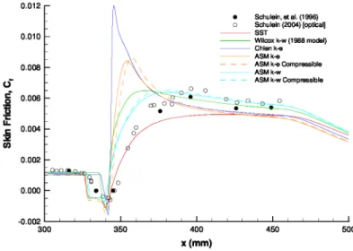
Mach number contours for an SST Wind-US solution are provided in Fig. 1. Comparisons of several solutions using linear two-equation turbulence models and EASMs with experimental data from Ref. 7 are provided in Fig. 2. It was observed that the linear k — c model solution provides poor agreement with experimental data, as would be expected for this flow. While the k — c based EASMs, with and without compressibility corrections, improve upon the linear k — c solution, the largest improvement is obtained by using the k—w formulations. The k—w EASMs provide improvement just past the shock impingement point. The solution obtained with the SST model also provides reasonable agreement in the post-shock region, with somewhat lower calculated skin friction than the experimental data and the other k — w models (linear and EASM). Future work is planned to investigate a blended k — c/k — w EASM. As described in a subsequent section of this paper, additional turbulence modeling work is underway to improve scalar transport modeling, which has significant effects on prediction of supersonic combustion.
Transition Modeling
Hypersonic flight vehicles frequently have boundary layers with significant laminar regions on vehicle forebodies and inlet surfaces because of the low freestream disturbances and low densities characteristic of the altitudes that such vehicles fly within. While flight tests can reproduce these atmospheric conditions, scaling issues due to Reynolds number affect the ability to reproduce the effects of boundary layer state, and in particular the point of transition. Ground test facilities frequently have freestream turbulence levels that are high enough to affect the transition point. Whereas the mechanism of transition in free flight is usually modal growth, the high freestream turbulence experienced by ground test articles frequently leads to bypass transition, in which the transition to turbulent flow is dictated by large freestream disturbances.
As a result, understanding the effects of different transition processes is desirable, and led to the motivation to implement a bypass transition model in Wind-US as part of this work.
Details of the formulation are provided in Ref. 8. The model is based on the SST turbulence model and was built starting from a previous SST-based transition model. 9–11 Several modifications were made to enable: (1) consistent solutions regardless of flow field initialization procedure and (2) fully turbulent flow beyond the transition region. In the following, we highlight only the key aspects of the implementation of the bypass transition model in Wind-US. Building upon the SST turbulence model, the key modification is made to the production term in the turbulent kinetic energy equation:
∂pk
+ ∂ pUj k = PTM · Pk - β* pwk +
ax (j
(µ+σkµt) ax I
where PTM is termed the “production term multiplier.” The w equation is not modified. The final form of the transition model that is recommended based on the work of Ref. 8 is:
PTM = 1 - 0.94(PTM1 + PTM2) F3tanh ((y+/17)2) F3 = e-( Ret3 ) 2 (1 - P(Ret)) + 12P(Ret) P(Ret) = 2 .5 -(Ret-3)2 2 7r e 2 ⎧ ⎨ [(3.28 x 10⁻⁴ )Rev - (3.94 x 10⁻⁷ )Re 2v +(1.43 x 10⁻¹⁰ )Re3 ] ; Re v < 1000 v PTM1 = 1 - CPTM1 ⎩[0.12 + (1.00 x 10⁻⁵Re v] ; Rev > 1000 ⎧ ⎨- | K |0.4 Rev; PTM2= 80 ' ⎩0; 1.0 ≤ CPTM1 ≤ 2.0
where Rev is the vorticity-based Reynolds number, Ret is the turbulent Reynolds number, and the pressure gradient parameter, K, is given by
K = -
p2U3 [1 - M 2]
d
p (8)
In Refs. 10 and 11, PTM2was formulated for flows with significant internal flow pressure gradients, and specifically for flows within low pressure turbine stages. In all cases examined in this work and that of Ref. 8, where flows with significant pressure gradients were not examined, PTM2was not found to be significant.
This model is intended for flows where bypass transition is the key transition mechanism as opposed to transition dictated by modal growth. Validation of the new transition model was performed for flows ranging from incompressible to hypersonic conditions.
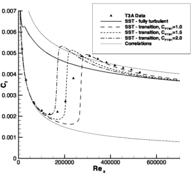
Figure 3 shows a comparison of simulations for a widely used data set for incompressible transition flow over a flat plate(referred to as the T3A test case 12 ). The fully turbulent SST solution shows the rapid transition (much closer to an entirely turbulent flow) that provided the motivation for the present work. It does a poor job of accurately capturing the early laminar behavior and the transition location which would lead to incorrect results for the drag on this flat plate. For the transition model solutions, the effect of a key parameter defined as part of this work, CPTM1 appearing in Eqn. 5, is to control the transition onset location. As with nearly all RANS-based transition prediction schemes, the width of the calculated transition region is shorter than indicated by experimental data. The solution with CPTM1 = 2.0 captures the transition onset location best while decreasing CPTM1 to 1.0 (the default value from original formulation) captures the end of the transition zone (i.e. where fully turbulent flow is realized) best.
Hypersonic flows present unique challenges in both modeling and experimentation. To baseline the present model’s ability to predict transitional behavior in hypersonic conditions, it was validated against transition data taken on sharp nose cones in the AEDC tunnel B at Mach 7.93. 13 The simulation is performed on a 7° half-angle cone, 40 inches (1016.3 mm) in length, in agreement with Ref. 13. As in the experiment, the wall temperature was set at 0.42T0, where T0 is the freestream stagnation temperature. Several unit Reynolds
K< 0 K> 0 (Recommended range) (1) (2) (3) (4) (5) (6) (7)
numbers (Re/m) were evaluated in Ref. 13 to provide a complete scan of the transition region. These data show good agreement across a range of Re/m, allowing the simulation to use only one, ,: 6.8E6 Re/m,
corresponding closely with the center of the experimental range. Inflow conditions are calculated to match those of Ref. 13. Insight from Ref. 14 indicated that an inlet freestream turbulence intensity of 1.25% was appropriate for AEDC tunnel B.
Figure 4 shows the Stanton number (St), as defined by Ref. 13 and as shown in Eq. 9, versus Reynolds number for the SST model alone, the SST transition model using CPTM1 = 1.0 and CPTM1 = 2.0, and the
experimental data.
St = q˙w/(ρ.U.(h(7'0) — h(7'w)) (9)
As in the incompressible case, the behavior in the transition region itself is overly abrupt. However, the model accurately captures the minimum heat transfer value, corresponding to transition onset for CPTM1 = 2.0
and the location where the flow becomes fully turbulent for CPTM1 = 1.0.
The transition model solutions are a marked improvement over the SST model alone, which vastly over-predicts the heat transfer by indicating a fully turbulent state from the leading edge of the test article. For a model in a high-speed wind tunnel that has a significant laminar region, the error due to transition onset can be quite large. The total heat transfer integrated over the length of the cone differs by 38.7% between the standard (fully turbulent) SST model and the SST-based transition model with CPTM1 = 1.0. Accurately
capturing this behavior is especially important when trying to evaluate thermal properties and heat transfer behavior near the tip of a hypersonic vehicle. The large discrepancy in heat transfer rates indicated by the two models would substantially alter the vehicle’s predicted temperature profile.
Conjugate Heat Transfer Modeling
Thermal management is of primary importance in hypersonic vehicle design and operation. Ground testing of hypersonic systems frequently requires active cooling to reduce temperatures in order to maintain structural integrity. In order to accurately model such configurations, a conjugate heat transfer capability coupled to the CFD solver is required. Efforts were initiated to develop such a conjugate conduction-convection heat transfer capability within the Wind-US framework. Details of the initial formulation and validation for water-cooled high-speed flow cases were provided in Ref. 15. The conjugate heat transfer method includes a solid body heat conduction solver, FOGO, which uses a finite-volume, cell-centered, multi-block structured-grid discretization. FOGO also includes empirically-based boundary conditions to evaluate flow boiling (i.e., forced convection plus nucleate or film boiling) heat transfer effects due to coolant flows, similar to the approach suggested by Shope. 1s The FOGO code is run in parallel with Wind-US to exchange flow information from Wind-US with heat transfer information provided by FOGO. Subsequent to this initial work, a specialized two-phase pressure-based RANS solver, called COOL, was developed and validated to permit the option to analytically model coolant flows. 17 As described in Ref. 17, the three solvers have been run in a loosely-coupled manner, but efforts are continuing to more tightly couple the solvers for difficult problems and time-dependent flows.
One of the test cases that has been investigated with the Wind-US/FOGO/COOL combination is a
H2 — O2 rocket test described in Ref. 18. In these experiments, a two-dimensional convergent-divergent
rocket nozzle produced an exhaust consisting largely of H2O over a series of three water-cooled copper panels. The experimental configuration had two sidewalls to enable the flow expansion to occur in a roughly two-dimensional manner along the panels. The water temperature rise in each section was measured as well as panel surface temperatures using thermocouples and temperature sensitive paint. A fourth sacrifice section was attached to the final calorimeter section. The undersides of each of the three copper panels were in contact with the eight water coolant channels. However, the coolant channels did not extend the entire length of each panel.
Run 96 was chosen from the tests of Ref. 18 since this test was successfully repeated and involved the most extreme heat transfer levels. Based on the available combustion chamber stagnation pressure and oxidizer/fuel ratio, the Chemical Equilibrium and Applications (CEA) code 19 from NASA Glenn Research Center was utilized to estimate the resulting stagnation temperature and exhaust products. The inflow stagnation conditions were set to Po = 34.27 bar and 7'o = 3557 K. Video from the panel tests showed that
afterburning occured just downstream of the calorimeter, indicating it was necessary to incorporate finite-rate chemical kinetics. The 7-species, 8-reaction H2-air model from Evans and Shexnayder 20 was utilized.
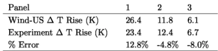
nozzle flow is significantly underexpanded, which results in an oblique shock system in the developing plume. The impingement of the oblique shocks on the calorimeter surface produces an increase in the local heat transfer to the calorimeter surface. A comparison of the Wind-US/FOGO/COOL calculations is made with experimental data for the measured heat transfer to the cooling water for each panel in Table 1. The total error for heat transfer over all of the panels was approximately 10%. More details of the simulation, including specifics of the flow modeling in the coolant passages, is provide in Ref. 17. In comparison to previous work described in Ref. 15, the most recent analysis described here demonstrates the improved predictive capability enabled by the RANS solver for the coolant flow (in contrast to an empirical-only approach) and the finite-rate kinetics for the developing rocket plume.
Panel
Wind-US Δ T Rise (K) 26.4 11.8 6.1 Experiment Δ T Rise (K) 23.4 12.4 6.7
% Error 12.8% -4.8% -8.0%
Table 1. Heat Transfer to Cooled Panels
Further development of the conjugate heat transfer capability is continuing. A new heat conduction code is under development which includes the ability to specify the temperature or heat flux on any boundary. To take advantage of this analysis tool, a surface data interface library has also been developed to provide a general mechanism for transferring data between stand-alone applications along shared surfaces. This library will enable coupling of Wind-US not only to the heat transfer solver but to other solvers for multidisciplinary analyses.
Scramjet Modeling
The Wind-US code has been recently applied to experimental scramjet propulsion system configurations. One of these is a configuration located at the University of Virginia (UVA) which has been used for several years to investigate dual-mode ramjet/scramjet engine behavior. 21,22 This configuration consists of a two-dimensional convergent-divergent nozzle providing a Mach 2 flow to a rectangular isolator. Downstream of the isolator, an unswept ramp contains a single round fuel injector which provides unheated hydrogen to a combustor section. The burned flow then enters a divergent nozzle and then exhausts to the freestream. The fuel injector geometry is a convergent-divergent nozzle. In experiments that are currently being sponsored by NASA under its Fundamental Aeronautics Program, the dual-mode behavior of this ramjet/scramjet configuration is being investigated with clean air and vitiated air heated to approximately 1200 K to simulate Mach 5+ flight conditions. This core flow is the same for all cases with fuel pressure varied to provide a range of equivalence ratios up to approximately 0.4. Clean and vitiated air cases are being investigated to determine test media effects on the dual-mode ramjet/scramjet behavior.
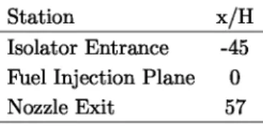
Calculations have been underway with Wind-US to simulate a series of these experimental cases. Prior to initiating these simulations, significant work was done as part of this overall project to update the chemically-reacting flow solver and remove inconsistencies that previously limited the ability of Wind-US to be used for chemically-reacting flow problems. In the current work, we have used the 7-species, 8-step H2-air kinetics mechanism due to Evans and Shexnayder 20 modified to include third body efficiencies other than unity, as taken from the model of Jachimowski. 23 In Ref. 24, the Evans-Shexnayder model including these modified third body efficiencies was shown to significantly improve the combustion behavior for the reference H2-vitiated air test case of Burrows and Kurkov. 25 Initial calculations with this kinetics mechanism exhibited difficulties in maintaining combustion for the UVA scramjet configuration. Although this was eventually rectified using lower activation energies at the initiation of a calculation, a simplified kinetics model employing a single-step mechanism with a very fast forward reaction rate was also employed as in Ref. 22. This simpified one-step mechanism was taken from a three-step mechanism utilized for ethylene-air combustion as described in Ref. 26. Several fuel equivalence ratios were investigated with Wind-US, ranging from fuel-off to an equivalence ratio of 0.39. In this discussion, we will consider an intermediate equivalence ratio (0.26) case.
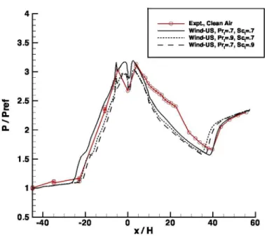
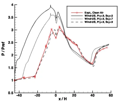
con-figuration through the combustor and initial part of the nozzle for a clean air case with a fuel equivalence ratio of 0.26 using the simplified kinetics approach. A comparison of experimental and calculated pressure distributions along the centerline of the top wall is shown in Fig. 7 for the single-step mechanism and in Fig. 8 for the Evans and Shexnayder 8-step mechanism with modified third body efficiencies. For the pressure distributions shown in Figs. 7 - 9, Table 2 shows the key positions in the UVA scramjet configuration. For the 1-step kinetics approach, three Wind-US solutions are presented in which the turbulent Prandtl and Schmidt numbers were varied. For the 8-step mechanism, the turbulent Prandtl number was held fixed while the Schmidt number was varied. While not shown here, variations in the turbulent Prandtl number were also investigated for the 8-step mechanism approach but did not exhibit the large variations observed for the turbulent Schmidt number. It is interesting to note that for the 1-step kinetics, there are only small varia-tions in the resultant pressure distribuvaria-tions. This is likely the case because the very high forward reaction rate makes the modeled combustion process less sensitive to the precise species concentration and local static temperature. In examining the significantly higher sensitivity associated with the more sophisticated 8-step kinetics, it is interesting to note that had only the Sct = 0.9 case been run, the agreement with experimental
data would have been judged to be excellent. However, this particular setting for Sct offers no guarantee of
equivalent success for other equivalence ratios.
Station x/H
Isolator Entrance -45 Fuel Injection Plane 0 Nozzle Exit 57
Table 2. Key positions for UVA scramjet configuration
Instead, the important thing to note is that the current common practice of setting constant values to Prt
and Sct for modeling scalar transport is very likely inadequate for the complex flows occurring in scramjet
systems. This finding has been been reported elsewhere, such as in Ref. 26. Current work under this project is beginning to investigate variable Prandtl/Schmidt number formulations to be used for improving the modeling of turbulent heat and mass transport in scramjet configurations such as the one considered here.
In many high enthalpy test facilities simulating high Mach number flight conditions, it is necessary to utilize a flow stream that has combustion by-products (or vitiates). A major focus of the experiments in the UVA scramjet facility is to compare the effects of vitiated air with clean air for a Mach 5 enthalpy simulated propulsion flow stream. Modeling the effects of vitiates on supersonic combustion behavior re-quires a kinetics mechanism that accounts for the thermodynamic differences associated with the presence of species different from that of clean air and also the influence of the contaminants on properties affecting the combustion process. Current efforts are underway in this project to implement and utilize a 13-species, 27-reaction mechanism 27,28 designed for vitiated air simulations. However, as an initial approximation, the single step mechanism described previously in this report has the capability to represent at least the ther-modynamic effects of the presence of CO2 and H2O vitiation. A comparison of experimentally measured and computed pressure distributions for nearly identical equivalence ratios is shown in Fig. 9 for vitiation levels corresponding to 3.7% CO2 and 5.5% H2O on a mole basis. While the trends of lower pressure for
the vitiated case are exhibited by both the experiments and the computations, clearly the computations do not indicate as large differences between the clean air and vitiated air approaches. As previously described, the single step mechanism can only reproduce the thermodynamic effects and not the vitiation effects on the kinetic behavior. It is hoped that employing the 13-species, 27-reaction mechanism will enable both effects to be modeled.
Conclusions
Physical modeling improvements to the Wind-US CFD code have been completed in order to improve the capabilities of Wind-US to complement hypersonic testing. A boundary layer transition model was implemented to improve the prediction of flows in which bypass transition, associated with relatively high freestream turbulence intensities that are characteristic of wind tunnel facilities used for high Mach number
testing, is the dominant transition mechanism. It was shown that the bypass transition model enables significantly more accurate predictions of boundary layer quantities such as skin friction and overall integrated quantities such as viscous drag and total heat load in comparison with predictions obtained using a two-equation turbulence model with no transition formulation. In the area of turbulence modeling, it was shown that k — w based formulations enabled the better predictions than k — c formulations for a Mach 5 shock-wave boundary layer interaction problem. Further, EASM models showed improved accuracy over linear models.
A conjugate conduction-convection heat transfer capability was developed for use with Wind-US. This capability should significantly improve the ability to model the large number of hypersonic flows in which heat transfer has significant effects on system operation and performance. Further, this conjugate conduction-convection heat transfer formulation should enhance the ability to predict and prevent potential structural failures due to heating in the ground testing environment. The Wind-US/conjugate heat transfer system represents a truly multidisciplinary capability as was demonstrated for a rocket exhaust validation case in which the rocket plume was modeled with Wind-US in turbulent mode and using finite-rate chemistry, conduction through the calorimeter panels was modeled with FOGO, and the coolant flow was simulated with a new pressure-based incompressible solver called COOL.
Significant work was performed to update the chemically reacting flow solver and remove inconsistencies that previously limited the ability of Wind-US to be used for chemically reacting flow problems. Following these upgrades, Wind-US was applied to the UVA dual-mode scramjet experimental configuration. These simulations modeled the entire direct-connect flow path from the facility nozzle through the isolator, combus-tor, and exhaust nozzle. Calculations using a simplified 1-step kinetics mechanism and more standard 8-step mechanism were examined. In addition, variations in the turbulent Prandtl and Schmidt numbers were also considered. The qualitative behavior of the scramjet operation was reproduced by the Wind-US calcula-tions for a fuel equivalence ratio set to 0.26, which is intermediate for the experiments under consideration. However, the sensitivity to kinetics and the turbulent scalar transport constants, which is characteristic of not only Wind-US but all CFD approaches, shows that there remains significant work in physical modeling needed to improve the reliability of CFD applied to scramjet flows.
Future Work
Future work will include the following: Simulations of the UVA scramjet configuration will continue with emphasis placed on improving the prediction of the vitiated air effects and reducing the sensitivity of the predictions to the models for scalar transport, namely the turbulent Prandtl and Schmidt numbers. The 13-species, 27-reaction mechanism 27, 28
will be examined in attempts to address both of these issues. In addition, work is currently underway to use a locally-varying turbulent Prandtl and Schmidt number approach where additional turbulent transport equations will be solved for the enthalpy and mass fraction variances. In addition, attempts will be made to reproduce the ram-to-scram mode transition behavior observed in the experiments when varying the fuel equivalence ratio. Work to upgrade the unstructured solver is nearly complete. This should enable Wind-US users to take advantage of the grid generation benefits for difficult geometries associated with unstructured grids. Finally, the simulation of time-dependent hypersonic problems involving moving grids will be explored. This will likely include the simulation of a combined cycle configuration with two inlets undergoing propulsion mode transition and a simulation of high Mach number stage separation.
References
'Nelson, C. C. and Power, G. D., “CHSSI Project CFD-7: The NPARC Alliance Flow Simulation System,” AIAA-2001-0594 , January 2001.
2 Menter, F. R., “Zonal Two Equation k - ω Turbulence Models for Aerodynamic Flows,” AIAA Journal, Vol. 32, No. 8, 1994, pp. 1598–1605.
3Wilcox, D. C., “Reassessment of the Scale-Determining Equation for Advanced Turbulence Models,” AIAA Journal, Vol. 26, No. 11, February 1988, pp. 1299–1310.
4Rumsey, C. L. and Gatski, T. B., “Recent Turbulence Model Advances Applied to Multielement Airfoil Computations,” Journal of Aircraft, Vol. 38, No. 5, September 2001, pp. 904–910.
5 Rumsey, C. L., Gatski, T. B., and Morrison, J. H., “Turbulence Model Predictions of Strongly Curved Flow in a U-Duct,” AIAA Journal, Vol. 38, No. 8, August 2000, pp. 1394–1402.
6Yoder, D. A., “Initial Evaluation of an Algebraic Reynolds Stress Model for Compressible Turbulent Shear Flows,” AIAA-2003-0548, January 2003.
7Schulein, E., “Optical Skin Friction Measurements in Short-Duration Facilities,” AIAA-2004-2115, June 2004.
8Denissen, N. A., Yoder, D. A., and Georgiadis, N. J., “Implementation and Validation of a Laminar-to-Turbulent Tran-sition Model in the Wind-US Code,” NASA TM 2008-215451, Sept. 2008.
9 Langtry, R., A Correlation-Based Transition Model using Local Variables for Unstructured Parallelized CFD Codes, Ph.D. thesis, University of Stuttgart, 2006.
10Langtry, R. B. and Sjolander, S. A., “Prediction of Transition for Attached and Separated Shear Layers in Turbomachin-ery,” AIAA-2002-3641, July 2002.
11 Menter, F., Ferreira, J. C., Esch, T., and Konno, B., “The SST Turbulence Model with Improved Wall Treatment for Heat Transfer Predictions in Gas Turbines,” Proceedings of the International Gas Turbine Congress - IGTC2003-TS-059, November 2003.
12 Savill, A. M., “Some Recent Progress in the Turbulence Modeling of By-pass Transition,” Near-Wall Turbulent Flows, edited by C. S. R.M.C. So and B. Launder, 1993, pp. 829–848.
13 Kimmel, R. L., “The Effect of Pressure Gradients on Transition Zone Length in Hypersonic Boundary Layers,” Journal of Fluids Engineering, Vol. 119, March 1997, pp. 36–41.
14McDaniel, R. D. and Hassan, H. A., “Role of Bypass Transition in Conventional Hypersonic Facilities,” AIAA-2001-0209, January 2001.
15 Engblom, W. A., Fletcher, B., and Georgiadis, N. J., “Validation of Conjugate Heat-Transfer Capability for Water-Cooled High-Speed Flows,” AIAA-2007-4392, June 2007.
16 Shope, F. L., “Conjugate Conduction-Convection Heat Transfer with a High-speed Boundary Layer,” Journal of Ther-mophysics and Heat Transfer, Vol. 8, No. 2, 1994, pp. 275–283.
17Engblom, W. A., Fletcher, B., and Georgiadis, N. J., “Validation of High-Fidelity Fluid-Thermal Simulation Capability for Water-Cooled High-Speed Flow Devices,” AIAA-2008-4653, July 2008.
18 Dickens, K. W., Linne, D. L., and Georgiadis, N. J., “Experiment and Modeling of a Rocket Engine Heat Flux Environ-ment for Materials Testing,” AIAA-2003-0283, January 2003.
19 McBride, B. and Gordon, S., “Computer Program for Calculation of Complex Chemical Equilibrium Compositions and Applications, II. Users Manual and Program Description,” NASA RP 1311, June 1996.
20 Evans, J. and Shexnayder, C., “Influence of Chemical Kinetics and Unmixedness on Burning in Supersonic Hydrogen Flames,” AIAA Journal, Vol. 18, No. 2, February 1979, pp. 805–811.
21 Goyne, C. P., McDaniel, J. C., Quagliaroli, T. M., Krauss, R. H., and Day, S. W., “Dual-Mode Combustion of Hydrogen in a Mach 5 Continuous-Flow Facility,” Journal of Propulsion and Power, Vol. 17, No. 6, 2001, pp. 1313–1318.
22 Goyne, C. P., Rodriguez, C. G., McDaniel, J. C., Krauss, R. H., and McClinton, C. R., “Experimental and Numerical Study of a Dual-Mode Scramjet Combustor,” Journal of Propulsion and Power, Vol. 22, No. 3, 2006, pp. 481–489.
23 Jachimowski, C., “An Analysis of Combustion Studies in Shock Expansion Tunnels and Reflected Shock Tunnels,” NASA TP 3224, July 1992.
24Engblom, W., Frate, F., and Nelson, C., “Progress in Validation of Wind-US for Ramjet/Scramjet Combustion,” AIAA-2005-1000, January 2005.
25 Burrows, M. and Kurkov, A., “Analytical and Experimental Study of Supersonic Combustion of Hydrogen in a Vitiated Airstream,” NASA TM-X 2828, Sept. 1973.
26 Baurle, R. and Eklund, D., “Analysis of Dual-Mode Hydrocarbon Scramjet Operation at Mach 4-6.5,” Journal of Propul-sion and Power, Vol. 18, No. 5, Sept. 2002, pp. 990–1002.
27 “Reduced Kinetic Mechanisms for Applications in Combustion Systems,” Lecture Notes in Physics, edited by N. Peter
and B. Rogg, Springer Verlag, 1993.
28 Chelliah, H., Krauss, R., and McDaniel, J., “Modeling of Vitiation Effects on H2-O2 Combustion Using Reduced Reaction Mechanisms,” AIAA-94-2577, June 1994.
M: 0.0 0.5 1.0 1.5 2.0 2.5 3.0 3.5 4.0 4.5 5.0
r.%
0 100 200 300 400 500
x (mm)
Figure 1. Mach number contours for shock-wave boundary-layer interaction problem
0.012 0.010 0.008 V \ c 0.006 °' • IL
4
0.0040
0.002 0.000 -0.002 300 350 • Schulein, et al. (1996) o Schulein (2004) [optical] SST Wilcox k-w (1988 model) Chien k-e • ASM k-e• • • • • ASM k-e Compressible • ASM k-w
• • • • • ASM k-w Compressible
400 450 500
x (mm)
0.007 0.006 0.005 0.004
V
0.003 0.002 0.001 400000 600000 Rex 0 0 200000 A T3A Data SST - fully turbulent — — — SST - transition, CPTM1=1.0 - - - SST - transition, CPTM1=1.5 — - — - — - SST - transition, CPTM1=2.0 Correlations^-Figure 3. Incompressible transition comparison
0.01 • Re/m=3.3E6 • Re/m=3.9E6 n Re/m=6.6E6 ♦ Re/m=8.2E6 SST - fully turbulent SST - transition, CPTM1 =1.0 - - - SST - transition, CPTM1 = 2.0 0.001 ``^- ♦•e ^ t» 4.^' I 1E+06 1E+07 Rex
Figure 6. Water vapor contours for scramjet combustor
4
Exp^., Clean Air Wind-US, Pr^=.7, Sc^=.7 --- Wind-US, Pr^=.9, Sc^=.7 3.5 — — — Wind-US, Pr^=.7, Sc^=.9 3 (A. -I VV 2.5
a
a
2 ;i 1.5 1 0.5 I -40 -20 0 20 40 60 x/H4 3.5 3 2.5 a r
a
2
r r r 1.5 r 1 — — 0.5 -40 -20--e-- Expt., Clean Air Wind-US, Prt=.9, Sct=.5
• Wind-US, Prt=.9, Sct=.7
— — — Wind-US, Prt=.9, Sct=.9
0 20 40 60
x/H
Figure 8. Pressure distributions for scramjet flow case using 8-step mechanism
4 Expt., Clean Air
Wind-US, Clean Air ---o--- Expt., Vitiated Air --- Wind-US, Vitiated Air
3.5 3 2.5 9. a ^'
a
2 1.5 m 1 0.5 -40 -20 0I 20 L 40 60 x/HREPORT DOCUMENTATION PAGE Form Approved
OMB No. 0704-0188
The public reporting burden for this collection of information is estimated to average 1 hour per response, including the time for reviewing instructions, searching existing data sources, gathering and maintaining the data needed, and completing and reviewing the collection of information. Send comments regarding this burden estimate or any other aspect of this collection of information, including suggestions for reducing this burden, to Department of Defense, Washington Headquarters Services, Directorate for Information Operations and Reports (0704-0188), 1215 Jefferson Davis Highway, Suite 1204, Arlington, VA 22202-4302. Respondents should be aware that notwithstanding any other provision of law, no person shall be subject to any penalty for failing to comply with a collection of information if it does not display a currently valid OMB control number.
PLEASE DO NOT RETURN YOUR FORM TO THE ABOVE ADDRESS.
1. REPORT DATE (DD-MM-YYYY) 2. REPORT TYPE 3. DATES COVERED (From - To)
01-07-2009 Technical Memorandum
4. TITLE AND SUBTITLE 5a. CONTRACT NUMBER
Wind-US Code Physical Modeling Improvements to Complement Hypersonic Testing and Evaluation
5b. GRANT NUMBER
5c. PROGRAM ELEMENT NUMBER
6. AUTHOR(S) 5d. PROJECT NUMBER
Georgiadis, Nicholas, J.; Yoder, Dennis, A.; Towne, Charles, S.; Engblom, William, A.; Bhagwandin, Vishal, A.; Power, Greg, D.; Lankford, Dennis, W.; Nelson, Christopher, C.
5e. TASK NUMBER
5f. WORK UNIT NUMBER
WBS 599489.02.07.03.03.02.01
7. PERFORMING ORGANIZATION NAME(S) AND ADDRESS(ES) 8. PERFORMING ORGANIZATION
National Aeronautics and Space Administration REPORT NUMBER
John H. Glenn Research Center at Lewis Field E-16931
Cleveland, Ohio 44135-3191
9. SPONSORING/MONITORING AGENCY NAME(S) AND ADDRESS(ES) 10. SPONSORING/MONITOR'S
National Aeronautics and Space Administration ACRONYM(S)
Washington, DC 20546-0001 NASA; AIAA
11. SPONSORING/MONITORING REPORT NUMBER
NASA/TM-2009-215615; AIAA-2009-193
12. DISTRIBUTION/AVAILABILITY STATEMENT
Unclassified-Unlimited Subject Categories: 01 and 07
Available electronically at http://gltrs.grc.nasa.gov
This publication is available from the NASA Center for AeroSpace Information, 443-757-5802
13. SUPPLEMENTARY NOTES
14. ABSTRACT
This report gives an overview of physical modeling enhancements to the Wind-US flow solver which were made to improve the capabilities for simulation of hypersonic flows and the reliability of computations to complement hypersonic testing. The improvements include advanced turbulence models, a bypass transition model, a conjugate (or closely coupled to vehicle structure) conduction-convection heat transfer capability, and an upgraded high-speed combustion solver. A Mach 5 shock-wave boundary layer interaction problem is used to investigate the benefits of k-
s
and k-w based explicit algebraic stress turbulence models relative to linear two-equation models. The bypass transition model is validated using data from experiments for incompressible boundary layers and a Mach 7.9 cone flow. The conjugate heat transfer method is validated for a test case involving reacting H 2- O2 rocket exhaust over cooled calorimeter panels. A dual-mode scramjet configuration is investigated using both a simplified 1-step kinetics mechanism and an 8-step mechanism. Additionally, variations in the turbulent Prandtl and Schmidt numbers are considered for this scramjet configuration.15. SUBJECT TERMS
Hypersonics; Turbulence; Transition; Heat transfer; Scramjet
16. SECURITY CLASSIFICATION OF: 17. LIMITATION OF 18. NUMBER 19a. NAME OF RESPONSIBLE PERSON
ABSTRACT OF
PAGES STI Help Desk (email:[email protected])
a. REPORT b. ABSTRACT c. THIS 19b. TELEPHONE NUMBER (include area code)
U U PAGE UU 20 443-757-5802
U
Standard Form 298 (Rev. 8-98) Prescribed by ANSI Std. Z39-18