Hogeschool van
Amsterdam
Domein techniek
Aviation studies
Flight AVI 685 EHAM-PANC
Flight planning & operations
Aviation Studies International Airlines
Group 2D
•
Michael Dick
•
Sandrine Doolhoff
•
Timo van Lochem
•
Barry van Niekerk
•
Sebastian Post
•
Marc Sinck
•
Jan Luis van der Ster
•
Niels Venterink
Summary
Project team 2D of the dispatch centre from Aviation Studies International Airline Operational Control Centre (OCC) has the assignment to make a flight planning for a flight with a Boeing 747 from Amsterdam Schiphol Airport (EHAM) to Ted Stevens International Airport Anchorage (PANC). The flight planning should result in a Briefing Package, which consists of the operational flight plan, ATS flight plan, mass and balance of the aircraft and the weather of the airports. The operational flight plan has information for the pilot about the flight including the route and waypoints, the enroute weather. ATS flight plan has been written for the air traffic controllers and be used by search and rescue if necessary. The flight plan consists of the flight heading and the details of the aircraft, crew and cargo on board.
At EHAM there are goods ready to be shipped to the airport PANC. The goods will be flown on a Boeing 747-400 Extended Range Freighter. Among the goods are 12 horses which should be treated according the Life Animal Regulations (LAR). Also an Boeing 777 engine of 7830kg must be loaded on board. The goods are loaded into the Boeing 747 following the load sheet, which gives the weight and balance of the aircraft so that the center of gravity lies on a vantage point for the flight. The maximum weight of a fully loaded aircraft without fuel is called Maximum Zero Fuel Weight (MZFW). With the maximum fuel included the Maximum Take Off Weight (MTOW) is obtained. The Boeing has some malfunctions; inoperative brake units and engine ignitor failures. According to the Minimum Equipment List (MEL) it is possible to fly with up to 2 defective brake units but the brake force will be reduced by 10 to 15%. Also in accordance with the MEL, it is possible to fly with 4 out of 8 ignitors deactivated. Thus the aircraft satisfies all this regulations so the aircraft may depart.
The aircraft will take-off from EHAM runway 18L because of the wind angle of 160 degrees, following the Standard Instrument Departure charts (SID) the flight turns east and heading north towards his first waypoint. The flight continuing the step climb towards waypoint ANDIK up to flight level 320. By heading west from EHAM to PANC the flight will be flying on the even flight levels. Due to climbing the pilots can make the most economical use of the fuel, but the aircraft has too much weight to climb higher than FL320. In the northern hemisphere there are not many flight routes so the flight uses random routing, where in planning phase within 150nm a planned waypoint is made to fly the optimal route. En-route, the aircraft has burned fuel and is light enough to climb towards FL340 and further on the route towards FL360. For emergency situations, en-route alternates have to be within the fuel range of the planned route, these emergency situations are decompression or two engines inoperative (N-2). The en-route alternates are Stavenger Sola airport (ENZV) and Kangerlussuaq airport (BGSF). For the en-route alternates the contincency fuel is 5% of the trip fuel, but fuel policy states that this amount may be decreased to 3% of the trip fuel when an en-route alternate aerodrome is located within a circle with a radius equal to 20% of the total flight plan distance, with the centre located at 25% of the total distance from the destination aerodrome. The en-route alternate Fairbanks Int. Airport meets these requirements so we can use 3% contincency fuel. At the waypoint NENANA the descent begins with the standard approach route towards PANC. When the approach to PANC fails the flight will be diverting to the alternate Fairbanks Int. Airport (PAFA). When the planning phase is completed and the pilots and the air traffic control submit the briefing package the operational phase starts. Flight AVI685 is successfully loaded and has departed from EHAM, where after three and a half hours flying a significant meteorological information (SIGMET) arrives at the OCC that the volcano Mt Spurr is erupting. This takes place at 21:00 UTC. The ash cloud will be right above PANC when flight AVI685 would arrive; at 01.52 UTC. Thus the flight cannot land on the destination airport. The dispatcher should pass this message to inform the flight crew and the Senior Operation Controller (SOC). The Flight Crew can be informed with the Aircraft Communications Addressing and by the Reporting System (ACARS), the ACARS printer will print the SIGMET for the pilots to read. If everyone is informed an inflight re-planning should be made. Three options are examined, namely the return to EHAM, landing at the airport alternate PAFA or divert to Vancouver International airport (CYVR). To determine what the best solution is for flight AV685 there are selection criteria established and weighting factor set. The selection criteria consist of efficiency,
The costs are also included in the selection criteria. The consequences for the customer, the horses are more rested when they have a comfortable flight. And the consequences for the crew, the total amount of hours the crew has to operate in total and the remaining time they are granted affects the workload.
Conform the selection criteria the best solution is PAFA, because this alternate is on the route to Anchorage. The advantage of this is that there is enough fuel on-board to land at PAFA and fly to Anchorage without refueling the aircraft. This means that there are no extra fuel costs. Because the alternate is en-route, the delay is minimized by no deviation of the route. Flight AVI685 will arrive at PAFA at 01.22 UTC. The ash cloud of Mt Spurr is blown over PANC at 12.00 UTC so the crew had more than enough time to rest, thus the workload of the crew is low. Flight AVI685 arriving at Ted Stevens International Airport (PANC) with delay and a stopover at Fairbanks International Airport, where the flight will wait for the ash cloud to pass. Where the new cargo on PANC is already waiting, the return flight from PANC will have a delay back to Schiphol (EHAM), but will be able to arrive safely.
Content
Introduction ... 1
1
Principles of flight planning ... 2
1.1 Operating Control Centre ... 2
1.1.1 Dispatch operations ... 2
1.1.2 Load control ... 3
1.1.3 Meteorology ... 3
1.1.4 Aircraft routing ... 3
1.1.5 Crew scheduling, tracking and accommodations ... 3
1.1.6 Airport customer service ... 3
1.1.7 Corporate security ... 3
1.1.8 Maintenance centre ... 3
1.1.9 Emergency operations centre ... 3
1.2 Efficient planning ... 3
1.2.1 Weather ... 3
1.2.2 Altitude ... 4
1.2.3 Cruise system... 4
1.2.4 Flight information regions ... 4
1.2.5 NOTAM ... 5 1.2.6 Runway condition ... 5 1.2.7 AOC ... 5 1.2.8 Alternate ... 5 1.3 Navigation ... 5 1.3.1 Principles of Navigation ... 5
1.3.2 North Atlantic airspace ... 7
1.3.3 Navigation Methods ... 8 1.3.4 Aeronautical Charts ... 9 1.4 Metrology ... 10 1.4.1 METAR ... 10 1.4.2 TAF ... 10 1.4.3 ATIS ... 11 1.4.4 SIGMET ... 11
1.4.5 Significant Weather Charts ... 14
1.4.6 Upper wind and temperature chart ... 15
1.5 Boeing 747-400ERF Specification and Equipment ... 15
1.5.1 Aircraft Performance ... 15
1.5.2 Payload bay layout ... 17
1.5.3 Minimum equipment list (MEL) ... 17
1.5.4 Navigation systems 747-400ERF ... 18
1.5.5 Aircraft technical log ... 19
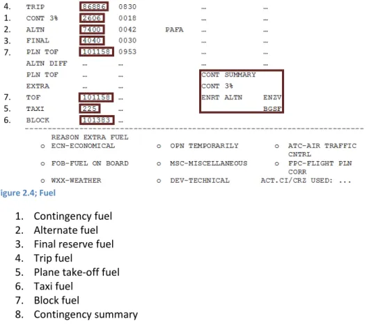
1.6 Fuel ... 19
1.6.1 Types Fuel ... 19
1.6.2 Required amount of fuel ... 21
1.7 Payload ... 21
1.7.1 Mass & Balance ... 21
1.7.2 NOTOC ... 22
1.8 Flight plans ... 23
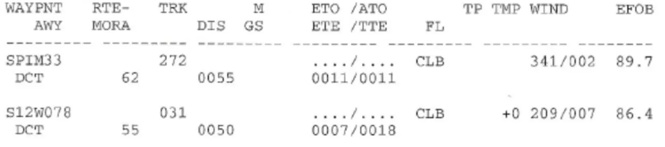
1.8.1 Operational flight plan ... 23
1.8.2 ATS Flight Plan ... 25
1.9 Regulations ... 25
1.9.3 Specific Load Regulations ... 26 1.9.4 Flight preparation ... 27 1.9.5 Planning minima ... 27 1.9.6 N-2 ... 28 1.9.7 Decompression ... 28
2
Flight planning ... 29
2.1 Airports ... 29 2.1.1 EHAM ... 29 2.1.2 PANC ... 29 2.1.3 Alternates ... 29 2.2 Weather ... 30 2.2.1 EHAM ... 30 2.2.2 Cruise ... 30 2.2.3 PANC ... 30 2.2.4 Alternate PAFA ... 30 2.3 Malfunctions ... 312.3.1 Brake Unit malfunction ... 31
2.3.2 Engine ignitor malfunction ... 31
2.4 Route ... 31
2.4.1 Take-off... 31
2.4.2 En-route ... 32
2.4.3 Approach ... 32
2.5 Fuel ... 32
2.5.1 Fuel calculations for the OFP ... 32
2.5.2 Enroute alternates ... 34
2.6 Mass & Balance ... 35
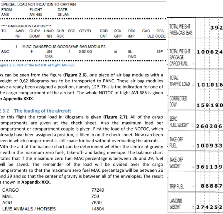
2.6.1 NOTOC flight AVI-685 ... 35
2.6.2 The loading of the aircraft ... 35
2.6.3 Load sheet flight AVI-685 ... 36
2.7 Briefing Package ... 36
2.7.1 Operational flight plan ... 36
2.7.2 ATS flight plan ... 37
3
OCC Failure Analyses ... 37
3.1 Flight AVI685 EHAM-PANC ... 37
3.1.1 MT Spurr ... 37
3.1.2 Flight ... 38
3.1.3 Crew and Payload ... 38
3.2 Operational Procedures ... 38
3.2.1 Inform the Flight crew ... 38
3.2.2 Inform the senior operations controller ... 38
3.3 Possible Solutions ... 38
3.3.1 Selection Criteria ... 38
3.3.2 Divert to Amsterdam Schiphol airport ... 40
3.3.3 Divert to Fairbanks ... 42
3.3.4 Divert to Vancouver International airport ... 44
3.3.5 Best Option ... 47 3.4 Debriefing ... 49
Content of Appendices ... 50
Bibliography ... I
Process report ... IV
Project Assignment ... V
Pyramid Model ... VI
Introduction
At January 28th 2014 a flight is planned from Schiphol (EHAM) to Ted Stevens Anchorage Airport (PANC). The flight will be carried out with a Boeing 747-400 Extended Range Freighter. At 17:30 UTC the plane should depart to Anchorage. The first task is to set up a briefing package with keeping efficiency and regulations in the occiput. The second task is to anticipate on the volcano eruption which is taking place during the flight. A solution has to be found to bring the cargo to PANC. A report is written about the briefing package and the solutions of the volcano eruption. The briefing package should be handed in at March 27th 2014 and the report at May 22th 2014.
For this assignment the Operation Control Center (OCC) of the Aviation Studies International Airline composes project group 2D. The project group consist out of 8 students of aviation studies and a project supervisor. Project group 2D is going to approach the assignment while the project supervisor monitors the progress. Every week another chairman is chosen during the 14 weeks of the project. This report will be divided in three chapters. To make a briefing package, knowledge about preparing a flight plan is necessary. So first the general knowledge of preparing a flight will be described. To construct and plan a certain route, knowledge about the navigation and meteorological, techniques is necessary to comprehend the limitations, of the aircraft. When all relevant regulations and issues are taken into account, two different flight plans can be set up; an operational flight plan and an air traffic services flight plan. The sections of the briefing package will be explained and why they are important for the flight. (Chapter one)
With the knowledge of chapter one, the briefing package for the flight from EHAM to PANC can be made. Every section of the briefing package will be described for this flight. This will be underpinned with a supporting explanation or calculation. These calculations include the waypoints and the estimated time between the waypoints needed to be determined by using the wind component. Another important aspect of the flight plan is the load sheet. With this calculation the pilots know the amount of payload which can be taken on the flight. Also destination alternates need to be determined. This is needed when a problem during the flight occurs. In the planning phase a malfunction on the aircraft will become apparent. It has to be examined if the aircraft can make a take-off without any delay. (Chapter two)
During the flight an irregularity will occur. This could delay the flight. Next to the destination airport, a volcano becomes active, so the airport will be closed. When landed on an alternate airport, a new flight plan has to be made. To give a solution for this problem, three possibilities will be elaborated. By comparing the possibilities, the best solution for the irregularity can be given. (Chapter three) The most important sources are the Flight Planning Performance Manual of the Boeing 747 and the planning charts. An attached report will contain the briefing package. The fuel calculations can be found in (Appendix XXVI)
1
Principles of flight planning
Some basic knowledge of flight planning is needed prior to draft a briefing package. This knowledge shall be discussed in this chapter. First of all, how arises a briefing package and what is it used for? Those questions can be answered with information about the operations control centre (1.1). The operations control centre will make a flight plan. This flight plan must be efficient so the airline has the least costs and the aircraft will arrive on time (1.2). Then what contains a briefing package? It turns out that all of the information that is required before, during and after the flight can be found in a briefing package. Therefore information about navigation (1.2), meteorology (1.4), and the aircraft that will carry out the flight (1.5), fuel (1.6) and payload (1.7) is needed. The major part of that information is also needed to create a flight plan (1.8). At last, there are also rules for ensuring safety and comfort of the flight which must be included into the flight planning (1.9).
1.1
Operating Control Centre
The principles of the flight emerge in the operations control centre. The purpose of an operations control centre is to bring all of the divisions that have a voice in the operation of an airline under the same roof to allow a better flow of communication. The following divisions can be found in an operations control centre: dispatch operations (1.1.1), load control (1.1.2), meteorology (1.1.3), aircraft routing (1.1.4), crew scheduling, tracking and accommodations (1.1.5), airport customer service (1.1.6), corporate security (1.1.7), maintenance centre (1.1.8) and emergency operations centre (1.1.9). All those divisions take care of the flight. Some prepare the flights, some provide good conditions for crew and passengers and others are there to help when irregularities occur. Eventually they all ensure a safe and economically good flight.
1.1.1
Dispatch operations
Dispatch operations are concerned with the flight itself. They provide the briefing package which gives the pilot and the air traffic controllers the information needed about the flight. Dispatch operations are subdivided into dispatch (1.1.1.a), navigation (1.1.1.b), sector managers (1.1.1.c) and air traffic centre operations (1.1.1.d).
1.1.1.a Dispatch
A flight dispatcher’s job is to prepare the flight plan for all of the flights for an airline. Therefore they look at the weather at the origin and the destination of the flight as well as the weather at the higher altitudes. If necessary, they will adjust the standard flight route so that the aircraft will fly around hazardous weather.
A flight dispatcher also communicates with the flight crew so that he can update them about weather changes or other alterations. So a fight dispatcher monitors the flight.
1.1.1.b Navigation
Navigation monitors and updates airways. They build standard flight routes and obtain over flight permits and landing permits if necessary. Also they monitor airports which allow them to take action when they find out that a runway or an airport is closed for some time.
1.1.1.c Sector managers
Sector managers are head of an aircraft or fleet. They make sure that their aircrafts are running on time. If a problem occurs, like a damaged wing or a computer failure, they have a few options; delay, swap or cancel. Sector managers work close with a lot of other divisions because the sector manager’s decision affects those other divisions too.
1.1.1.d Air traffic centre operations
The air traffic centre operations monitor and communicate to dispatchers about ground stops, ground delay programs and required and recommended re-routes. This group also monitors the competitors of the airline so that the passengers get the same quality of on time service as the passengers should have had if he or she had chosen for the competitor.
1.1.2
Load control
Load control ensures the weight and balance of an aircraft. This is one of the documents which get into the briefing package for the pilot. Hereby the pilot has the correct gross weight of the aircraft and the correct trim setting. Load control warns the dispatchers when a flight is overweight. Also load control produces the calculation of fuel-loading.
1.1.3
Meteorology
Meteorology forecasts weather like turbulence and upper air wind patterns. They also create SIGMETs for their airline’s flights. Meteorology forecasts also special weathers like hurricanes and winter storms. The sector managers often make use of this information to make their decision of cancelling the flight. Meteorology itself affects the fuel calculation, route of the flight and scheduling too.
1.1.4
Aircraft routing
Aircraft routing decides which aircraft will carry out the flight. Thereby they keep an eye on where and when which aircraft must be for maintenance service.
1.1.5
Crew scheduling, tracking and accommodations
Crew scheduling decides which pilot and which stewards carry out which flight. A crew tracking is responsible for monitor the crew, especially when irregularities occur. They ensure that if a crew team misses their next flight, another crew team will take over. Crew accommodations ensure an accommodation for the crew so that when a flight is delayed the crew will have a place to stay.
1.1.6
Airport customer service
Airport customer service advocates for the passengers. This division is responsible for the passengers during delays and cancelations. They also help arrange tight connections.
1.1.7
Corporate security
Corporate security monitors the security of the whole airline. They assist the other divisions to meet the regulatory security requirements.
1.1.8
Maintenance centre
Maintenance centre monitors when an aircraft needs a maintenance service. They also provide technical assistance to the pilots in the air and the maintenance crew on the ground.
1.1.9
Emergency operations centre
Emergency operations centre springs into action when disruptive events occur such as a volcano eruption or a hurricane arises. In such cases the emergency operations centre can make decisions for all of the aircrafts of the airline.
1.2
Efficient planning
Using fuel as efficiently as possible is a high priority, thus all possible measures are taken to fly in optimal efficient conditions providing that it does not affect the flight duration drastically. The circumstances that are taken into account are the weather conditions (1.2.1), as well as the optimal pressure altitude (1.2.2), cruise speed and duration of the flight (1.2.3), flight information regions and non-radar airspace (1.2.4), Notice To Airmen (NOTAM) information (1.2.5), runway conditions (1.2.6), Air Operator Certificates (AOC) (1.2.7), and alternate planning (1.2.8).
1.2.1
Weather
It goes without saying that flying through stormy weather is not preferred. Therefore when planning the flight, the weather enroute should be investigated. Flying around the bad weather is recommended to ensure a safe and comfortable flight.
is recommended to fly in the jet stream when it provides the aircraft tailwind and to fly above or underneath the jet stream when it provides the aircraft headwind, or simply around it. This recommendation follows logically from shortening the flight duration. The same goes for ‘common’ winds.
The outside air temperature (OAT) affects the performance of the engines of the aircraft. At higher temperatures the density of the air decreases. This results in a lower mass flow of air to go through the engine which results into less weight to accelerate. Eventually less thrust is generated. So at high temperatures the engine has to work harder to create the same amount of thrust it creates at low temperatures. It is recommended to operate through low temperature areas so that the engine is more economically used.
1.2.2
Altitude
The altitude has a significant influence on the aircrafts ability to produce lift, it also affects the drag and the thrust delivered by the engines, because the air density and pressure decrease with altitude. At lower altitudes, the air density is higher causing the drag to be unnecessary high. As the density decreases with altitude, the angle of attack has to increase in order to generate enough lift, which in turn increases the drag and thus the required thrust. However, as a result of weight loss due to using fuel, the required amount of lift will decrease as well, thus allowing the aircraft to operate at greater altitudes.
The airways which are used to operate on are divided into lower and upper air routes. The major difference, regarding to planning, between those two air routes is the air density again. The upper air routes are in the upper airspace so the density is low. Therefore there are less air molecules which collide with the aircraft per second. The aircraft is certified to collide with at least the amount of air molecules which are on ground level. Therefore the aircraft can operate at higher speeds when the aircraft operates on higher altitudes. It is recommended to operate at the optimum altitude which is the highest possible altitude regarding the weight of the aircraft.
1.2.3
Cruise system
The cruise speed and the duration of the flight are inseparable. It is preferred to minimize the flight duration but then the aircraft will operate with a high cruise speed. This high cruise speed will result into high fuel consumption which is equal to high costs. Airlines usually give the pilot a Costs Index (CI) (Equation 1.1) which is linked to a certain cruise speed in the FMS. General airline costs covers amongst others the costs to may land on an airport, the salary of the crew and the costs the airline will get when passengers miss there transfer flight.
𝐶𝐼
=
𝐺𝑒𝑛𝑒𝑟𝑎𝑙𝐹𝑢𝑒𝑙𝑎𝑖𝑟𝑙𝑖𝑛𝑒𝑐𝑜𝑠𝑡𝑠𝑐𝑜𝑠𝑡𝑠CI = costs index
Fuel costs = costs of the fuel on board at the start of the flight General airline costs = costs which the airline has or is going to make Equation 1.1; Cost index
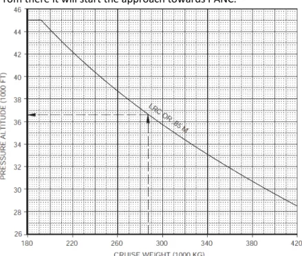
Another speed at which can be flown is the max range cruise speed. This is the cruise speed at which the aircraft can reach the maximum range. The advantage of this speed is that the fuel is used as efficient as it can be. The disadvantage of this speed is that it is a very low speed.
Since there is no indication of a preferred cost index and the max range cruise speed is a very slow speed recommended is the long range cruise speed. This is the speed at which the aircraft reaches 99% of the maximum range.
1.2.4
Flight information regions
Flight information regions (FIR’s) are regions at which one air traffic company provides the flight information. Every time an aircraft enters another FIR, the aircraft will be supervised by another controller. This brings an amount of costs with it. It is recommended to fly a route with as little as possible FIR in it.
1.2.5
NOTAM
NOTAMs give critical information about the airport and its region. Thus when a part of the airspace around the airport or a runway may be temporary closed, the NOTAM describes it. The NOTAM stated also when high obstacles are moved around the airport. Basically the NOTAM will tell when something differs from normal circumstances. It is recommended to read the NOTAM prior to planning to flight so that the flight is prepared for the issues which may be come.
1.2.6
Runway condition
A runway is not always in its best condition. For example, it may be contaminated or there may be slush. A runway is contaminated when more than 25% of the runway surface area within the required length and width being used is covered by surface water more than 3.0mm or by slush or loose snow equivalent to 3.0mm of water, snow which has been compressed into a solid mass or ice including wet ice. Information about the runway is amongst others given in a runway state message (Appendix I) which may be provided by a METAR. The NOTAM gives also information about the runways. It is recommended to depart and arrive from a runway which is in good condition.
1.2.7
AOC
An Air Operator Certificate (AOC) is a certificate authorizing an operator to carry out specified commercial air transport operations. An AOC specifies the:
- Name and location (principal place of business) of the operator. - Date of issue and period of validity.
- Description of the type of operations authorized. - Type(s) of aircraft(s) authorized for use.
- Registration markings of the authorized aircraft(s) except that operators may obtain approval for a system to inform the Authority about the registration markings for aircrafts operated under its AOC.
- Authorized areas of operation.
- Special limitations/authorizations and approvals. It is recommended to keep in mind the limitations of the AOC.
1.2.8
Alternate
An alternate must be near the destination airport. If an alternate is too close to the destination airport there is a risk that if the destination airport is closed due to weather conditions, the alternate will be too. Also when choosing a military airport as an alternate accessibility must be considered. This is, because if the aircraft only has to divert because of problems at the destination airport and not at the aircraft, it is not always allowed to land at a military airport.
1.3
Navigation
During and before a flight a pilot should be able to navigate to its destination with the principles of navigation, which must be applied to a moving aircraft (1.3.1). The principles of navigation will help the pilot to find the shortest possible route and offer assistance to the pilot when the pilot needs to divert to another airport. Therefore the pilot flies through specific airspaces. The north Atlantic airspace is discussed further (1.3.2). During flight the pilot uses, when navigating, multiple navigation methods (1.3.3). Several maps of airports and airways are available. These maps provide a specific route around an airport or airway. The pilot uses charts of the planned route to give an overview of the departure and arrival procedures on de required airports (1.3.4).
1.3.1
Principles of Navigation
The principles of navigation depend on the earth. The earth is not round and has a different shape (1.3.1.a). It is possible to determine the heading of the aircraft when using the shape of the earth (1.3.1.b). When the pilot knows his heading he can start to navigate around the earth using the navigation tracks (1.3.1.c).
1.3.1.a The shape of the Earth
The earth is not a round sphere; usually for the shape of the earth a spheroid is used. The geographical poles are the points where the "short" axis of the spheroid reaches the surface (Appendix IIA). The top of the spheroid is called the North Pole and at the bottom of the spheroid the South Pole. Seen from above the earth turns "counter clockwise" around the North Pole. The vertical axis is about 45 km shorter than the horizontal axis of the Earth.
1.3.1.b Heading
During flight a pilot uses different values for the North Pole to navigate to his destination. These values are known as:
1. True North 2. Magnetic North 3. Compass North
Ad 1. True North
True North (TN) is used for flight planning tracks and is defined as the direction of the tangent of the meridian in the direction of the geographic north. When planning a flight over 65 North there should be planned on True North.
Ad 2. Magnetic North
On different flight charts the Magnetic North (MN) is used. The magnetic North varies with time because of the change of the magnetic field of the earth. The difference between true north and magnetic north is called variation.
Ad 3. Compass North
The compass north will be marked on the compass of the aircraft and is not the true north; the compass can be converted to magnetic north or true north. The difference between magnetic north and Compass North is called the deviation.
1.3.1.c Earth Tracks
A position on the earth is determined with the co-ordinates across the width and length of the earth. To know more about the position on earth, like the position on the upper side or bottom side of the earth, we need to further subdivide the earth in:
1. Great Circles
2. Meridians and Longitude 3. Small Circles and Latitude
Ad 1. Great Circle
The earth can be divided in Great Circles (GC) and small circles (Appendix IIB). A great circle centre always intersects the centre of the earth and is the largest circle on the surface of the earth. The distance of a great circle is described in degrees, 1 degree on the Great Circle is 60 minutes and these are used for distance navigation. One GC minute is equal to one Nautical Mile (NM) which is 1852 meter. The GC distance is the shortest distance between two points. Radio signals follow the GC path, which is important for scheduling of radio soundings.
Ad 2. Meridians and Longitude
Meridians are half GCs which are connected to each other at the two poles. The meridians are indicated in degrees, as seen from the centre of the earth, starting from a reference meridian. The reference meridian is the 0° meridian and called the Greenwich meridian (Appendix IIA), named after the village near London. The position east or west of the Greenwich meridian is called the length, east or west longitude in 0-180 degrees.
Ad 3. Small Circle and Latitude
Besides the 180 "vertical" meridians which form together 360 GC, there is one great circle which intersects the rotation axis of the earth perpendicularly. This is the equator. The equator divides the
earth into the northern- and the southern hemisphere. The other circles that intersect the axis of rotation of the earth perpendicular are all Small Circles (Appendix IIB). The small circles can be identified as North or South relative to the equator. The position north or south of the equator is called the width, north or south latitude in 0-90 degrees.
1.3.2
North Atlantic airspace
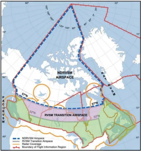
In the north Atlantic airspace different kinds of airspaces exist (Figure 1.1). Such as, Reduced Vertical Separation Minima (RVSM) and Northern Canadian RVSM (NDRVSM). To operate in RVSM airspace the aircraft must be RVSM approved. Before flying with a RVSM approved aircraft the operator has to be authorized and has to request clearance for RVSM operations (1.3.2.a). Also tracks are made in the north Atlantic airspace. In the morning and evening North Atlantic Organized Track System (NAT OTS) provides fixed tracks indicated with a letter (1.3.2.b).
Figure 1.1; North Atlantic airspace 1.3.2.a RVSM
North Atlantic Minimum Navigation Performance Specification Airspace (NAT MNPSA) is an airspace just north of the Canary Islands (27°N) up to the North Pole, between FL285 and FL420.
RVSM airspace has been established within the confines of MNPS airspace and associated transition areas. From FL290 the altitude extends up to the RVSM altitude limit of FL410, the maximum altitude that is certificated for that type of aircraft and the limitations of altitude for example, cruise and buffet. To ensure the safe application of the separation minimum, authorization has to be requested to fly in RVSM airspace. In RVSM airspace, 1000 ft. vertical separation is applied between approved aircraft. The longitudinal separation is as follows: 10 minutes if the Mach number of the preceding aircraft is equal to or greater than that of the following aircraft. 9 minutes if the aircraft in front is M0.02 faster. 8 minutes if the aircraft in front is M0.03 faster. 7 minutes if the aircraft in front is M0.04 faster. 6 minutes if the aircraft in front is M0.05 faster. 5 minutes if the aircraft in front is M0.06 faster. If the aircraft do not report over a common point and are out of radar range the separation is 15 minutes. Lateral separation is 60 NM.
1.3.2.b NAT OTS
The NAT OTS provides fixed tracks for trans-Atlantic traffic in the morning and the evening. The traffic flows is Westbound during the day and Eastbound overnight. Each North Atlantic Organized Track is identified by a letter. The westbound tracks begin with the letter A as the most northerly track and continue vertically down with B, C, D and so on (depending on how many tracks are needed to accommodate the forecast traffic). The eastbound tracks begin with Z as the most southerly track and continue vertically upward with Y, Z, W etc. The NAT OTS operates twice during each 24 hour period. Westbound system is operational from 1130 to 1900 UTC. Eastbound system is operational from 0100 to 0800 UTC. Aircraft may fly on random routes which remain clear of the OTS or may fly on any route that joins or leaves an outer track of the OTS.
Position reports should be made at designated reporting points and at the significant points listed in the Flight Plan. If, on a NAT track report, at the points listed in the track message and at designated reporting points. The general guide is that ATC should have reports in roughly hourly intervals. As a rule North of 70°N every 20° of longitude. South of 70° every 10° of longitude. Any changes to ETAs of 3 minutes or more should be advised to ATC. Report to ATC on reaching a new cruising level. For flights outside the domestic ATS route network, position should be expressed in terms of latitude and longitude except when flying over named reporting points.
1.3.3
Navigation Methods
The pilot has a number of methods to navigate the aircraft to its destination. The initial aircraft, which made longer flights, navigated on compass navigation (1.3.3.a). After several years, navigating developed and began to navigate using radio signals (1.3.3.b). Around airports it was important to properly navigate, this happened with precision navigation (1.3.3.c). This is fully developed to precision approaches to the runway itself. Nowadays also navigate with help from the satellites; this is called GPS navigation (1.3.3.d).
1.3.3.a Compass Navigation
Compass navigation relies on the earth’s magnetic field. This magnetic field exists surrounding the earth. The magnetic field has force lines from the North Pole to the South Pole. This magnetic field can be used by the pilot to get information about the aircraft’s movement and so can the pilot adjust his heading. The device which gives this information is called a compass, which provides the direction to the Magnetic North. The compass uses the magnetic force lines and works without an electrical system. The magnetic field of the earth is not constant so near a magnetic area the heading can be incorrect that is because there is variation in this fields. Because of the new navigation methods today the compass is only used as a backup device.
1.3.3.b Radio Navigation
Today the aviation uses a radio navigation system. This is used during different phases of flight, including cruise, approach and landing. Using radio beacons on the land during flight, the position of the aircraft can be determined. It is possible to follow a radio signal because the signal is constantly broadcast. A pilot can follow the beacons by tuning on to the frequency of the beacons. The position of the aircraft in relative with the beacon is displayed on the radio navigation device in the cockpit. A radio signal cannot pass through the earth's surface so a beacon which is far away of the aircraft is not always in reach.
1.3.3.c Precision Navigation
An airport works as an intersection for the airways, so around an airport the aircraft needs to be precisely navigated. During landing a precision approach system is used. An ILS system is a precision approach system and most airports use this ILS system. An ILS system consists of a localizer (at the end of the track), glide slope (next to the runway), marker beacons, and approach lighting (Appendix IIIA). The ILS system transmits signals that are received by an ILS receiver in a modern aircraft. This is done with a signal in the vertical direction and a signal in the horizontal direction and these signals are called a glide slope. The ILS will navigate the aircraft in a particular track on the runway. Each
category of the ILS system is categorized by the sight and the distance to which the ILS system can put the aircraft in front of the runway.
1.3.3.d Global Positioning system
Navigating through satellites is called Global Positioning System (GPS). The navigation system consists of satellites that move around the earth in permanent lanes. The signals of the satellites are received by a GPS receiver. This receiver can receive the signals and decode them. There are at least three satellites necessary to determine the position on earth. The receiver operates through measure the distance between the satellite and the receiver, taking into account the delay of the signal. The signals are converted into latitude, longitude and altitude.
1.3.4
Aeronautical Charts
When a flight is planned several charts are used. Those charts can be projected in a specific kind of ways (1.3.4.a). Besides those differences there multiple kind of chart which are used during the flight planning. Starting with an aerodrome chart (1.3.4.b) followed by a departure chart (1.3.4.c) and an en-route chart (1.3.4.d) closing with an approach chart (1.3.4.e).
1.3.4.a Chart projections
An earth chart projection is a projection of the elliptical earth on a map. There are three main projections:
1. Mercator projection 2. Lambert projection 3. Azimuthal projection
Which chart projections is used, can usually be found on the upper right corner of the chart.
Ad 1. Mercator projection
The Mercator projection is a cylindrical projection. This projection can be identified by the vertically meridians and the horizontally parallels. Hereby the great circle is a curve. Another characteristic of this projection is that the chart is conformal. A disadvantage of this projection is that surface deformations occur. The further a country is from the equator, the bigger it is projected. The poles are even infinitely large.
Ad 2. Lambert projection
A Lambert projection is a conformal conic projection. This projection can be identified by the converging meridians and the parallels which are concentric arcs. Hereby the great circle is almost straight line. The difference from a true straight line is negligible. A Lambert projection has two standard parallels. At the standard parallel the earth is conform and not deformed displayed. The rest of the chart is conforming but deformed displayed, but this deformation is not as large as the deformation on a Mercator chart.
Ad 3. Azimuthal projection
An Azimuthal projection is a chart projection where the projection surface is flat and touches or cut the earth. A gnomonic Azimuthal projection has a projection point in the centre of the earth. Hereby the great circle is a straight line. When the projection point is the opposite geographic pole, the projection is called polar stereographic Azimuthal projection. In this projection the parallels are perfect circles. The meridians are perpendicularly on those parallels. This chart is conforming. When the point of contact is at the opposite meridian on the equator, the projection is called equatorial stereographic Azimuthal projection. When the point of contact is just on the opposite meridian, the projection is called oblique stereographic Azimuthal projection.
1.3.4.b Aerodrome chart
An aerodrome chart is a graphical latitude and longitude correct representation of the airport including such elements as: runways, taxiways, obstacles, buildings and ground features. Aerodrome charts, display also additional information such as communications, take-off and alternate minimums
the aerodrome to display more details of, for example, parking positions or low visibility taxiway routes.
1.3.4.c Standard Instrument Departure chart
Standard Instrument Departure charts, also called SID’s, show an IFR departure route. The route starts at the runway of an aerodrome and continues via a number of markers to a designated ATS route. It is possible that there are given a couple of standard ATC instructions to go besides the chart. The legend of this chart is explained in Appendix IVA.
1.3.4.d En-route chart
En-route charts are offered in high and low altitudes and are used for the cruise phase. Most of the en- route charts are Lambert conformal conic projections. On this chart are amongst others aerodromes, airways, minimum altitudes and waypoints displayed. The legend of this chart is explained in Appendix IVB.
1.3.4.e Standard Terminal Arrival Route chart
Standard Terminal Arrival Route charts, also called STAR’s, shows an IFR arrival route. The route starts at a designated ATS route and continues via a number of markers to a runway of an aerodrome. It is possible that there are given a couple of standard ATC instructions to go besides the chart. The legend of this chart is explained in Appendix IVA.
1.4
Metrology
As the weather can be very different in every area, meteorological reports are made for a large number of locations. These reports consist of uniform codes, which permit an efficient transmission of a large amount of information. These meteorological reports, which describe the current, forecasted and expected weather conditions, are Meteorological Aerodrome Reports (1.4.1), The Terminal Aerodrome Forecasts (1.4.2), the Automatic Terminal Information Services (1.4.3) and the Significant Meteorological Information (1.4.4). To describe the wind and temperature at specific flight levels, the significant weather charts (0) and the upper wind and temperature charts (1.4.6) are used.
1.4.1
METAR
Meteorological Aerodrome Report (METAR) is the most common meteorological information source in aviation. It’s a weather report on the current weather situation that routinely is prepared by the meteorological service at an airport. The weather report will be provided in METAR code to the fight crew. Weather observations in METAR code have a four-letter location indicator according to the standards of ICAO and WMO. These elements are listed in a specific sequence. The elements that can be found in the METAR are described in Appendix VA.
In case of a rapid change of weather condition or other critical circumstances, it is possible that the observations are updated. This is done by the Aviation Selected Special Weather Report (SPECI). SPECI is a supplement of the METAR.
1.4.2
TAF
The Terminal Aerodrome Forecast (TAF) is a forecast of the meteorological conditions at an aerodrome published in a concise statement for a certain period of time. TAFs are valid in general for a period of 24 or 30 hours a day and within an area of about five statute miles (approximately 1,609m) from the centre of an airport runway complex. The weather conditions in the TAF are coded similarly to those used in a METAR report.
A difference between a METAR and a TAF code is that the TAF does not contain QNH. Further in a TAF, the temperature and dew points are missing comparing to a METAR. But if they are given they are described at a different position then the METAR. An example of a TAF code is shown in Appendix VB.
1.4.3
ATIS
ATIS is short for Automatic Terminal Information Service. This is a radio service which is generally offered to departing and approaching traffic at the larger airports. ATIS consists of an automatic message that is continuously transmitted to one or more frequencies in the Very High Frequencies (VHF). It is virtually identical to the METAR. The message contains information about the current weather at the airport and operational details. The message always begins with a letter indication. The letter moves up in alphabetical order if there is a change of the data. If any significant weather condition or a runway direction is changed, the information in the ATIS will be adjusted. This is done at least every hour.
1.4.4
SIGMET
During the flight the weather is a real factor for the safety of the aircraft. To fly safe it is really useful to know which weather can be expected, in particular significant weather changes constitute a potential risk. Meteorological offices are constant occupied with the task to intercept potential hazardous en-route weather for their responsible area. This information is the significant meteorological information (SIGMET).
A SIGMET warning is mostly broadcasted on the automatic terminal information system (ATIS) or meteorological information for aircraft in flight (VOLMET). The SIGMET exists out of three different parts and starts with the Header (1.4.4.a) which contains basic information about the SIGMET. The first line of the SIGMET (1.4.4.b) continues with the valid time of the SIGMET. As last the SIGMET end with the meteorological information (1.4.4.c) about the weather phenomena.
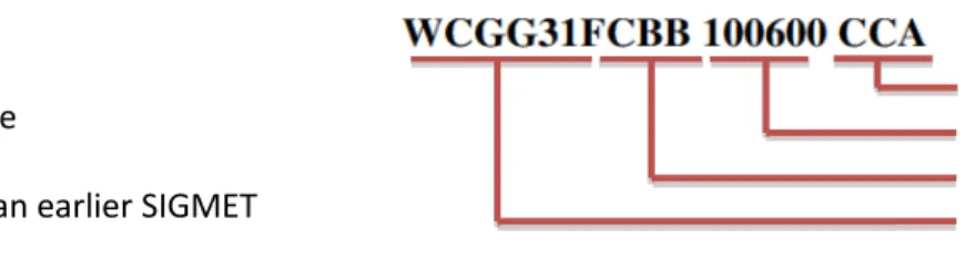
1.4.4.a Header
The header (Figure 1.2) contains different sort of information: 1. Bulletin identification
2. Communications centre 3. Date and time
4. Possible correction of an earlier SIGMET
Ad 1. Bulletin identification
The bulletin identification number starts with the data type designator (Table 1.1). After the sort of the SIGMET message follows the country and territory designators. The bulletin identification will finish with the bulletin number.
Abbreviation
Definition
WC
For tropical cyclones.
WV
For volcanic ash clouds.
WS
For weather warnings other than volcanic ash clouds and tropical cyclones.
Table 1.1; type of SIGMET messageAd 2. Communication centre
This part exists out of the ICAO code (four letters) from where the SIGMET message is sent. This is because the information is not going straight from the WMO to the aircraft, but with interposition of a communication centre.
Ad 3. Date and time
The first two numbers of this block show the date the message is sent, while the last four numbers shows the time the message is sent.
Ad 4. Possible Correction of an earlier SIGMET
It is always possible that there is sent a SIGMET message with wrong information. In that case there could be send a correction SIGMET. To make clear that the SIGMET contains a correction, the following codes at the end of the header CC. Where A is placed for the first correction, B for the
4 3 2 1 Figure 1.2; SIGMET header
1.4.4.b First line
The first line of the SIGMET (Figure 1.3) contains: 1. Location of ATS unit
2. Message identifier 3. SIGMET numbering 4. Valid period 5. Location of MWO
Ad 1. Location of ATS unit
ICAO code of the ATS unit that control the FIR or UIR for which the SIGMET is sent.
Ad 2. Message identifier
This part of the message only contains the word ‘SIGMET’ to identify that it is a SIGMET message.
Ad 3. SIGMET numbering
The SIGMET numbering starts counting at 0001UTC. The numbering could exist out of a maximum of three symbols.
Ad 4. Valid period
The period of which the SIGMET message is valid is written the same as the date and time in the header (1.4.4.a, Ad 3). The start and end time of the message separated by a slash.
Ad 5. Location of MWO
Also the location of the issuing MWO is showed in ICAO code. 1.4.4.c Weather information
The weather information in the SIGMET consists out of seven different parts: 1. Name of the FIR/UIR
2. Weather phenomena 3. Observed or forecast 4. Location
5. Level
6. Movement or expecting movement 7. Changes in intensity
Ad 1. Name of the FIR/UIR or CTA
Here is the corresponding FIR/UIR or CTA region placed.
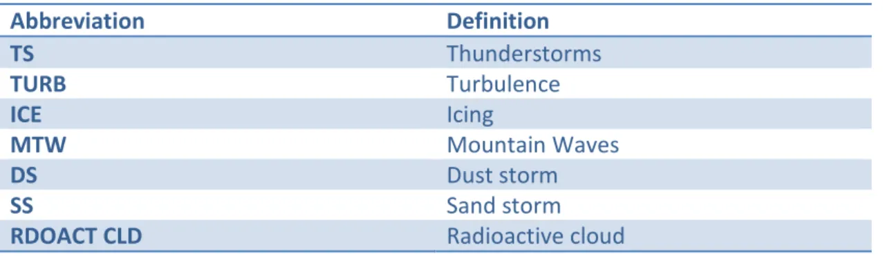
Ad 2. Weather phenomena
There are different shortcuts for every weather phenomena showed in Table 1.2.
Abbreviation
Definition
TS
Thunderstorms
TURB
Turbulence
ICE
Icing
MTW
Mountain Waves
DS
Dust storm
SS
Sand storm
RDOACT CLD
Radioactive cloud
Table 1.2; Weather phenomena abbreviations5 4 3 2 1 Figure 1.3; SIGMET first line
Ad 3. Observed or forecast
The information of the SIGMET could be an observation (OBS), forecast (FCST) or both. Also the time when the OBS is made is given.
Ad 4. Location
The location of the weather phenomena could be described in different ways. The most common ways are:
- Indication of the FIR with longitudinal coordinates - Indication of the FIR with latitudinal coordinates
- Indication of the FIR with longitudinal and latitudinal coordinates - ICAO code
- Other international geographical features
Ad 5. Level
Beside the geographical coordinates also the FL of the weather phenomena needed to be described. When this information is known, it is possible to climb or decent to minimize the harassment.
Ad 6. Movement or expecting movement
The movement (MOV) is given in KMH or in KT with one of the eight compass direction points. When no significant movement is expected the movement is replaced for STNR.
Ad 7. Changes in intensity
Beside the movement or change of the phenomena location also the intensity of the weather could intensify (INTSF), weaken (WKN) or could be constant (no change, NC).
Example:
Ad 8.
WSFR35 LFPW 021631 (HEADER)
LFRR SIGMET 1 VALID 021700/022100 LFPW- (VALID TIME)
LFRR BREST FIR/UIR SEV TURB FCST WI N4945 W00300 - N5000 W00200 -
N5000 W00015 - N4900 W00015 - N4845 W00245 SFC/FL060 STNR NC=(WEATHER INFO)
Ad 9.
The header tells that this SIGMET contains another weather phenomenon than volcanic clouds or a tropical cyclone. According to the third and fourth letters, FR, the corresponding country/ territory designator is France. The bulletin number is 35 and the communication centre is in Toulouse (LFPW). The SIGMET is send at 2 March at 16:31.
The ATS unit Brest (London, UK) controls the FIR/UIR for which the phenomenon is valid. This is the first SIGMET that is given since 0001UTC. The message is valid from 2 March 17:00 until 2 March 21:00 and is set up by the WMO in Toulouse.
The corresponding FIR/UIR is Brest and the forecast is severe (SEV) turbulence (TURB). The location of the turbulence is given in geographical coordinates and there is no significant movement expected (STNR) and change in intensity (NC).
Beside this standard format, there are different formats for tropical cyclones and volcanic eruptions/ash clouds. Because these are more exceptional situations and not relevant for the project they will not be described.
1.4.5
Significant Weather Charts
The significant weather (SIGWX) charts are provided by the World Area Forecast Centre (WAFC). The charts can be divided in Low level charts (<10000ft), medium/high level charts (10000ft to 40000ft) and high level charts (>25000ft). General the charts are issued every six hours, 00, 06, 12 and 18 UTC. The SIGWX charts contain the next information:
1. Jet Streams
2. Clear air turbulence 3. Tropopause levels 4. Cloud weather 5. Fronts
6. Volcanic activity
Ad 1. Jet streams
A jet stream is a relative narrow air current in the atmosphere which travels with a minimum speed of 80 knots, the speeds can increase to a several hundred knots. It is important to know where these jet streams are simply because they affect the performance of the aircraft. If an aircraft flies several hundreds or thousands of miles against a jet stream, the flight will take much longer and a lot more fuel will be burned. But when flying with a jet stream the ground speed will be much higher and a lot less fuel is needed for the flight. For flight planning it is the case to avoid or use the jet stream to get as much efficient as possible from the departure to the destination location. Beside the
Jet streams are showed as long black arrows. Above these arrows the speed of the jet stream is given with triangles and stripes. Each triangle is a speed of 50 knots and each feather is 10 knots, the short feathers are 5 knots. Under the jet stream arrow the flight level of the jet stream is given (Figure 1.4).
Ad 2. Clear air turbulence
Heavy turbulence can be better avoided than seek out. Turbulence in the high SIGWX chart will be showed as a dashed line; furthermore also the Flight level is indicated. The intensity of the turbulence is given with two different symbols, the left symbol is moderate turbulence and the right symbol indicates severe turbulence (Figure 1.5).
Ad 3. Tropopause levels
The tropopause levels are given in hundreds of feet placed in a squared box (Figure 1.6). It is useful to know when the tropopause starts, because from this altitude it is not efficient to climb further due to the constant temperature in the tropopause.
Ad 4. Cloud weather
In cloudy weather only turbulence and icing and visibility is measured at these heights. Not the base/top of the cloud is therefore measured, but the top of the turbulence and icing. Only moderate or severe icing or turbulence will be indicated. The areas will be showed with scalloped lines. The coverage of the area is given in a scale from 0 to 8, ISOL CB indicates a low coverage of the area, less than 1/8. OCNL CB indicates 1/8 to 4/8 coverage and FRQ CB indicates 5/8 or more coverage (Figure 1.7).
Ad 5. Fronts
The different fronts are given in the standard surface notation, a (blue) line with triangles is a cold front, a (red) line with hemispheres is a warm front, a combination of both at the one side is an occluded front and the one with both symbols but now alternating from side is a stationary front (Figure 1.8).
Figure 1.8 Fronts Figure 1.7; Cloud weather Figure 1.6; Tropopauselevels Figure 1.5; Clear air turbulence intensity symbols Figure 1.4; Jet stream
Ad 6. Tropical storms
There are two symbols to indicate if it is a tropical storm or hurricane. The symbol with the open body indicates that it is a tropical storm with wind speeds of 35 to 64 knots. The solid body will indicate a tropical cyclone with wind speeds above 64 knots (Figure 1.9). The location of the symbol is also the forecast condition for the concerning time.
Ad 7. Volcanic activity
Is given in with a volcanic symbol and scalloped lines with the heights of the ash cloud in hundreds of feet (Figure 1.10).
1.4.6
Upper wind and temperature chart
The upper wind and temperature chart is issued four times a day for eight different
flight levels, from FL050 to FL450. The wind speed and direction is indicated by wind feathers, where the wind speed indication works exactly the same as with the significant weather charts. Beside the wind also the temperature is given. Note that the temperature that is given seems to be positive, but for example 46 means -46 degrees. When the temperature is above zero than this will be indicated with PS, so PS4 will mean 4 degrees above zero. An example can be found in Appendix VI.
1.5
Boeing 747-400ERF Specification and Equipment
The Boeing 747-400ERF and its performance will be described (1.5.1), next the layout of the cargo room will be described (1.5.2). The minimum equipment list containing the most essential items of the aircraft (1.5.3). The Boeing 747-400ERF has several navigation systems (1.5.4). As last the aircraft technical log will be explained (1.5.5).
1.5.1
Aircraft Performance
First the specifications of the Boeing will be described (1.5.1.a). Secondly the rescue and firefighting index will be explained (1.5.1.b). As last, the required pavement what an airport need so a Boeing 747 can land on their runway will be explained (1.5.1.c).
1.5.1.a Specifications
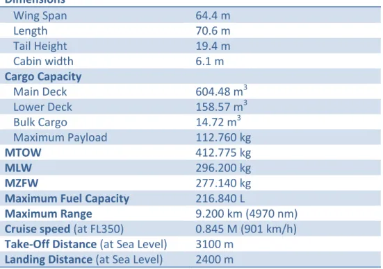
The flight from EHAM to PANC will be with a Boeing 747-400 Extended Range Freighter. In Table 1.3; Specifications of the Boeing 747-400 ERF the specifications of the Boeing 747-400ERF are shown.
Dimensions
Wing Span
64.4 m
Length
70.6 m
Tail Height
19.4 m
Cabin width
6.1 m
Cargo Capacity
Main Deck
604.48 m
3Lower Deck
158.57 m
3Bulk Cargo
14.72 m
3Maximum Payload
112.760 kg
MTOW
412.775 kg
MLW
296.200 kg
MZFW
277.140 kg
Maximum Fuel Capacity
216.840 L
Maximum Range
9.200 km (4970 nm)
Cruise speed
(at FL350)
0.845 M (901 km/h)
Take-Off Distance
(at Sea Level)
3100 m
Landing Distance
(at Sea Level)
2400 m
Table 1.3; Specifications of the Boeing 747-400 ERFFigure 1.10; Volcanic eruption
Figure 1.9; Tropical storms
1.5.1.b Aircraft Rescue and Fire Fighting index
An airport has to comply with the aircraft rescue and firefighting index (ARFF), so a Boeing 747-400 can land on the airport. The ARFF index is based on the length of the aircraft and the average daily departures. The index is shown in Table 1.4; Aircraft rescue and firefighting index.
Index
Length
A
Less than 27 m
B
From 26 m to less than 38 m
C
From 38 m to less than 48 m
D
From 48 m to less than 61 m
E
More than 61 m
Table 1.4; Aircraft rescue and firefighting index
When an airport has less than five daily departures of the longest aircraft, the index for the airport is allowed to be one lower the required index. For the Boeing 747-400 an index of E is needed, unless the airport has less than five departures, index D is sufficient.
1.5.1.c Pavement Classification Number
The Pavement Classification Number (PCN) consists of five parts. The first part is the number that indicates the load-carrying capacity of the pavement. The scale starts at one and ends on 130. One means a very weak pavement and 130 a very strong pavement. The second part is the letter F or R. This indicates of the pavement is flexible (F) or rigid (R). The third part indicates the strength of the pavement. The index goes from A to D.
A = high strength B = medium strength C = low strength D = very low strength
The fourth part indicates the maximum tire pressure. This index goes from W to Z. W = no maximum pressure
X = up to 1.5MPa Y = up to 1.0MPa Z = up to 0.5MPa
At last the T or U is used. This indicates whether the PCN is obtained by technical evaluation (T) or by practical experience (U).
Also every aircraft has its own Aircraft Classification Number (ACN). This number depends on the pavement and strength of the runway where the aircrafts land, for the Boeing 747 it can be found in Table 1.5. A Boeing 747-400 cannot land on a runway where the number of the ACN is higher than the number of the PCN.
Flexible Pavement (F)
Rigid Pavement (R)
Strength
A B
C
D
A
B
C
D
Boeing 747-400erf
57 63
78
100
59
69
81
92
Table 1.5; Aircraft classification number of the Boeing 747-400 ERF1.5.2
Payload bay layout
The Boeing 747-400ERF consists of a main deck and a lower deck. On the main deck 604,5 m3 of cargo can be stored and on the lower deck 173,3 m3 of cargo can be stored. The dimensions of the cargo doors are added in 0. The maximum payload is 112.760 kg.
When animals are transported in the cargo area, the pressure and temperature has to be acceptable for loving. The maximum pressure on the entire aircraft including the cargo area can be 648.1 millibar.
The B747 is divided in seven temperature zones: flight deck, upper deck, crew rest, forward and aft main deck, forward and aft lower lobe cargo zone. Bleed air is used to heat the zones. Before entering the bleed air in the zones it will be cooled down. Two pack temperature controllers (PTCs) regulate the amount of bleed air with valves. The temperature on flight deck, the upper deck, crew rest zone and main deck varies between 18 to 29 degrees of Celsius. The temperature in the forward and lower lobe cargo zone can be selected with a Temperature Selector. The temperature can be selected between 4 to 29 degrees of Celsius.
Engines can only be brought into the aircraft through the side cargo door. The nose door is too small for the engines. Engines will be loaded on the main deck.
1.5.3
Minimum equipment list (MEL)
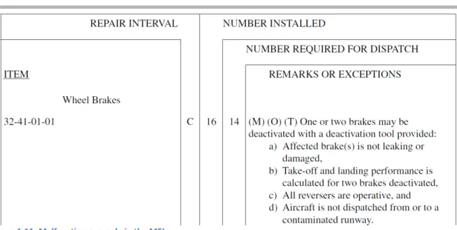
Any aircraft that operates must meet the minimum equipment list (MEL), this list contains the most important content for operations and the maintenance personnel , there is also a master minimum equipment list (MMEL) specifically designed for a particular type of aircraft. In this MMEL is set up that the operation is responsible for the new type of design and is approved by the state of design. By giving the example of the already known malfunction of the brakes the MEL can be explained (Figure 1.11). The MEL has a standard layout with every time a different malfunction described, where it says item with the given number. For this example it is 32-41-01-01.
The repair interval is divided in different repair time categories which are categorized as A, B, C and D Category A has a time interval which is given in the remarks, when the problem should be repaired. Next we got category B with an interval of three consecutive calendar days after discovery of the problem. Second last we got category C with an interval of ten consecutive calendar days after discovery of the problem. As last category D where the problem should be repaired within the time period of hundred and twenty consecutive calendar days after discovery.
Further the numbers of total installed items is given, but also the number of required items is displayed which is necessary for dispatch. Having less than this number restricts the operator for departing. With having enough installed items and meet the requirements which are described at the remarks or exceptions is authorized to depart. In that same framework are some abbreviations designated with the symbols (M), (O) and (T) these have different meanings.
“(M)” stands for maintenance. Qualified personnel may perform actions to repair the issue, where the Engineering Department is responsible for these procedures.
“(O)” stands for Operations. Authorized personnel, normally the flight crew or cabin crew perform these operations procedures which are noted in the MEL. The responsibility lies at the operator itself.
“(T)” is the technical deficiency which will be send during flight to stations along the route. The aircraft technical deficiency (aircraft registration, flight number and date). This information will be sent to OCC which are responsible for the displayed issues.
Figure 1.11; Malfunction example in the MEL
1.5.4
Navigation systems 747-400ERF
There are different navigation systems that is being used in the 747-400ERF. One of the methods is the Global Positioning System (GPS). There are several other methods that are being used this is the Inertial Reference System 1.5.4.a. Moreover, there is the radio navigation systems which will be described in 1.5.4.b and the weather radar in 1.5.4.c.
1.5.4.a Inertial Reference System (IRS)
The IRS is of great importance in determining several states of the aircraft by the aid of three laser gyros and three accelerometers. Data can be obtained of position, attitude of the aircraft, true and magnetic heading, wind speed and direction, speed, accelerations and altitude.
Three modes are available for obtaining the data which are needed for navigation. 1. Full alignment
2. Fast alignment 3. IRS attitude
Ad 1. Full alignment
This option is only available when the aircraft is parked; it takes ten minutes to complete the alignment. The one task that has to be done is to put the present position into the Control Display Unit (CDU).
Ad 2. Fast alignment
This option is completed in thirty seconds but lacks information about track, ground speed and attitude errors.
Ad 3. IRS attitude
When alignment is lost during flight, only information about attitude can get back by moving the selector to ATT. After thirty seconds the system provides the information, the accuracy depends on the movement of the aircraft. In a straight level of flight gives the best result.
1.5.4.b Radio Navigation Systems
Radio navigation is divided into several navigation equipment, these are: 1. Automatic Direction Finding (ADF)
2. Distance Measuring Equipment (DME) 3. Instrument Landing System (ILS) 4. VOR
Ad 1. Automatic Direction Finding (ADF)
The signals of the ADF follow the curve of the earth. With a frequency band of 190 KHz to 1750 KHz. When putting in the radio frequency which is previously determined in the direction of the determined flight path, the pointer will point into the direction of the station.
Ad 2. Distance Measuring Equipment (DME)
The aircraft send out a pulse which is captured by a ground beacon which intercept this signal and send out another pulse towards the aircraft. By measuring the time it takes and with the speed of the electromagnetic pulse of 300 000 km/s the distance horizontally from the aircraft to the beacon can be calculated.
Ad 3. Instrument Landing System (ILS)
ILS is used of assisting the pilot to follow the correct glideslope to descend to the runway safely and precisely. ILS is active in 3 ways, first the autopilot must be turned on and either the localizer or glideslope is captured. Second the flight director is turned on, and either the localizer or the glideslope is captured, and the airplane is below 500 feet radio altitude. And third ILS is active on the ground with an airplane heading within 45 degrees of the localizer seen from the front and the ground speed is greater than 40 knots.
Ad 4. VOR
The VOR transmits two signals simultaneously. One signal keeps sending in all directions and the other rotates around the station. When the aircraft picks up the signals and interpret it as a radial. 1.5.4.c Weather radar
When flying through the air, you always have to do with the weather. The weather can be seen with the weather radar, it consists of two receiver-transmitter units, an antenna and a control panel. It gives a visual image of what lies ahead. Turbulence can be detected by the radar this can only be sensed if there is sufficient rainfall. Therefore clear air turbulence cannot be found on the radar.
1.5.5
Aircraft technical log
The aircraft technical log is a sheet which is needed in every flight. It is an overview about the condition of the aircraft is, information such as technical en operational data can be found. Further all other malfunctions that can be detected.
1.6
Fuel
When the flight route is decided, the amount of required fuel to cover the distance can be calculated. In order to calculate how much fuel is required, the different types of fuel (1.6.1), as prescribed by EU-ops 1.255, are discussed. After which the fuel tables are examined, because these are required to calculate the necessary amount of fuel (1.6.2).
1.6.1
Types Fuel
The required amount of fuel is calculated for different flight phases, starting with the fuel to taxi to the runway (1.6.1.a), followed by the amount of fuel used from take-off to landing (1.6.1.b). Several different types of reserve fuel are required in case of unexpected circumstances (1.6.1.c). Also the captain may decide to bring extra fuel (1.6.1.d).