MovExp: A Versatile Visualization Tool for Human-Computer
Interaction Studies with 3D Performance and Biomechanical Data
Gregorio Palmas, Myroslav Bachynskyi, Antti Oulasvirta, Hans-Peter Seidel, Tino Weinkauf
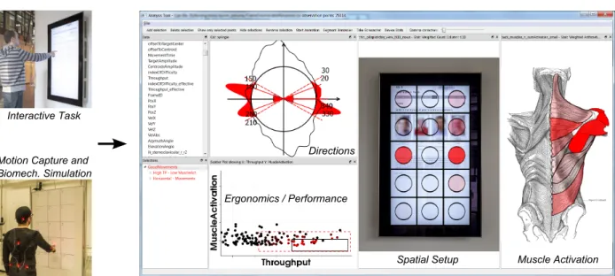
InteractiveATask MotionACaptureAandA Biomech.ASimulation Directions ErgonomicsA/APerformance SpatialASetupA MuscleAActivation
Figure 1. MovExp is a versatile visualization tool which supports the HCI experts in evaluating user interfaces by means of data coming from motion capture and biomechanical simulation. In this example, HCI experts were interested in finding a input region on a vertical public display, where movements are accurate, fast and least fatiguing. The screenshot on the right shows the analysis in our tool MovExp. The circular directions visualization was used to brush horizontal movements, and movements with high throughput and low muscle activation were selected on a scatter plot. These two selections were combined using anandoperator. Note how data is visualized on top of a photo of the public display, showing its spatial setup. We call this a case-specific visualization. TheErgonomics aspect of the data is visualized using a muscle view. The optimal region was identified to be in the middle of the display.
Abstract—In Human-Computer Interaction (HCI), experts seek to evaluate and compare the performance and ergonomics of user interfaces. Recently, a novel cost-efficient method for estimating physical ergonomics and performance has been introduced to HCI. It is based on optical motion capture and biomechanical simulation. It provides a rich source for analyzing human movements summarized in a multidimensional data set. Existing visualization tools do not sufficiently support the HCI experts in analyzing this data. We identified two shortcomings. First, appropriate visual encodings are missing particularly for the biomechanical aspects of the data. Second, the physical setup of the user interface cannot be incorporated explicitly into existing tools.
We present MovExp, a versatile visualization tool that supports the evaluation of user interfaces. In particular, it can be easily adapted by the HCI experts to include the physical setup that is being evaluated, and visualize the data on top of it. Furthermore, it provides a variety of visual encodings to communicate muscular loads, movement directions, and other specifics of HCI studies that employ motion capture and biomechanical simulation.
In this design study, we follow a problem-driven research approach. Based on a formalization of the visualization needs and the data structure, we formulate technical requirements for the visualization tool and present novel solutions to the analysis needs of the HCI experts. We show the utility of our tool with four case studies from the daily work of our HCI experts.
Index Terms—Information visualization, Design study, Human-Computer Interaction.
1 INTRODUCTION
This paper presents a design study in the application domain of Human-Computer Interaction (HCI). HCI is a multidisciplinary field investi-gating the design of user-friendly interactive systems. In particular in this paper, we focus on the study of input methods such as virtual
• Gregorio Palmas, Myroslav Bachynskyi, Antti Oulasvirta, Hans-Peter Seidel and Tino Weinkauf are with Max Planck Institute for Informatics E-mail: {gpalmas, mbachyns, oantti, hpseidel, weinkauf}@mpi-inf.mpg.de. Manuscript received 31 Mar. 2014; accepted 1 Aug. 2014; date of publication xx xxx 2014; date of current version xx xxx 2014.
For information on obtaining reprints of this article, please send e-mail to: [email protected].
and physical keyboards, trackball, mouse, stylus, tablet, and the light pen [19, 38, 44]. Extensive studies spanning over three decades have shown that two design concerns are of major importance for the suc-cess of a user interface: the physical ergonomics [18, 19] and the user performance [25, 38, 62]. Physical ergonomics include biomechanical factors such as muscular load. Typical indicators for user performance are speed and accuracy.
Recently, a method was proposed [11] that allows a cost-effective assessment of user performance and physical ergonomics. It works by first capturing the 3D movements of a human in a laboratory setting, and then numerically simulating the biomechanics. This is called motion-capture-based biomechanical simulation.The resulting data sets are multidimensional (typically around 400 variables) and provide a rich description of human movement. Furthermore, every HCI case study
introduces its ownspatial setupdefined by elements such as the posture space of the user, the positions of the interface, and environmental constraints.
The existing visualization tools do not sufficiently support the analy-sis needs of HCI researchers. We identified two major shortcomings: First, although generic visualizations could be used for all variables, they lack appropriate visual encodings, particularly for the biome-chanical aspects of the data. This makes generic visualizations often unintuitive or even cumbersome. Second, the physical setup of the user interface cannot be easily incorporated into existing tools. Hence, valuable information is left out from the analysis.
This paper presentsMovExp(Movement Explorer), a versatile vi-sualization tool for HCI data sets, particularly aimed at analyzing performance and biomechanical data. MovExp applies many known principles of multidimensional data visualization. We extend this line of research by giving the domain experts an easy way to incorporate the specific physical setup of a HCI case study. Essentially, they can create their own visual encodings which are fully synchronized via Linking & Brushing. This is crucial for mapping the movements of the user to the interface. The flexibility of this approach serves the short turnaround cycles required by some of the HCI studies. Furthermore, MovExp provides a variety of visual encodings to support the analysis of biomechanical data such as anatomical maps for ergonomics indices. The research leading to this paper followed the problem-driven approach as described in theDesign Study Methodologyof Sedlmair, Meyer, and Munzner [51]. We have worked with an HCI group for two years on empirical HCI projects that have led to three publications [10, 11, 47]. This design study contributes a) a detailed analysis of their visualization requirements,b) the design of MovExp including its novel technical solutions, andc) reflections throughout the process. We show the utility of our tool with a usage scenario and three case studies from the daily work of our HCI experts.
The paper has the following outline. Section 2 explains the Mocap-based biomechanical simulation process, introduces the HCI domain terminology and reports the related work. In Section 3, we analyze the visualization requirements, provide a data abstraction and develop specific technical requirements for MovExp. Section 4 gives details about the technical implementation. The utility of our approach is demonstrated in Section 5. We conclude with possible future research directions in Section 6.
2 BACKGROUND ANDRELATEDWORK 2.1 HCI Background
A significant part of Human-Computer Interaction (HCI) deals with the design and evaluation of user interfaces. While the design is often a creative part, the evaluation is commonly quantified by means of questionnaires, usage logs and physical measurements. The goal is an effective, efficient and user-friendly interface that supports one or more specific use cases.1Effectiveness and efficacy are to be evaluated with respect to the use case. We give two contrasting examples:
• An interface in a workplace environment should allow fast and accurate data entry, and the movements should not be strenuous.
• An interface for a fitness game (exergame) should demand strenu-ous movements, while their accuracy is of little importance. Performance and ergonomics play an important role in particular when evaluating input devices. Performancerefers to the speed and accuracy of a user’s movement. A well-established model of movement speed is Fitts’ law [39]: it captures the speed and accuracy of aimed movements in the single metric throughput (bits/s). Ergonomics de-scribes how well a user interface fits to the capabilities of humans. We are particularly concerned with physical ergonomics, which includes biomechanical aspects such as the demand on the muscular system (muscular load) or the amount of bending at joints.
1In HCI, the term “task” is commonly used to refer to what a user has to do or wants to do with a user interface. We rather write “use case” here to avoid confusion with the term “visualization task.”
There are several examples in the history that demonstrate the im-portance of ergonomics. Consider the fate of the light pen: Touted as the ideal input device for information workers, it foundered as it caused strain in shoulder and arm muscles [27]. More recently, users of vertical touchscreens for PCs complain about “the gorilla arm” due to holding up the arm and operating in such posture too long. Generally, to be able to replace an established input device such as the mouse or the physical keyboard, the newcomer should in the minimum match its level of ergonomics [43].
Different instruments exist to assess ergonomics, for example go-niometers, videometry, and electromyography (EMG). However, they are rarely used in HCI studies, since they are too expensive, constrain-ing, and specialized.
A new option for assessing ergonomics became recently available: biomechanical simulation [20, 21, 59]. The goal is to have a complete simulation of all biomechanical processes of a human movement. Ma-ture simulation software [21] and body models [28] are available. The input to a biomechanical simulation is the skeletal movement of the subject. This can be obtained by optical motion capture (mocap) as it is also known from the film industry: a subject wears a special suit with optical markers which are tracked with a number of cameras at several hundred Hertz [1]. Note that speed and accuracy can be directly inferred from the captured movements.
In other words, we can assess the performance and ergonomics of an input method simultaneously by capturing the movements of a subject and subsequently simulating the biomechanics of these movements. This method is calledmocap-based biomechanical simulation. In the recent past, such setups have been used in sports [48], medicine [37], and industrial ergonomics [41]. It is the goal of our collaboration to bring this method to HCI. Previous work in our collaboration includes a study on the validity of mocap-based biomechanical simulation for HCI scenarios [11]. The visualization work presented in this paper has not been published elsewhere.
Mocap-based biomechanical simulation is a cost-efficient estimation of physical ergonomics and performance in HCI studies. It does not restrict natural movement (much), making it possible to study full-body interactions where EMG recordings and other measurements are impractical. The method could thus improve the evaluation of input methods by better taking into account biomechanical stresses and muscle loads.
While the ergonomics of desktop-based UIs have been intensively studied, interactions “beyond the desktop” need more attention [36]. For example, tangible computing, tabletops and surfaces, mobile inter-action, and various forms of 3D interaction all insist on novel postures and movement types for input. Such interactions can be too demanding for long-term use, or they can be too easy as in the case of exergames.
2.2 Related Work
Mocap-based biomechanical simulation was only recently introduced to HCI. Previously, the different aspects of an interaction such as perfor-mance and ergonomics were typically collected in separate experiments, and also analyzed separately. As a result, there was no visualization tool available to our collaboration partners which allowed seamless work with all the four aspects of their data set. The available tools typically concentrate on a specific aspect and come without support for visualizations beyond scatter plot or line chart. We performed an ex-tensive literature review and summarize the results in the supplemental material.
2.2.1 Physical Ergonomics Tools
Ergonomics measurements are often performed by means of observa-tions, questionnaires, goniometes, videometry or EMG. For example, the Noraxon MRXP software records and processes EMG [2], the Lumbar Motion Monitor records angles at the backbone [15], and the Occupational Repetitive Actions tool allows to calculate OCRA in-dices [17]. These tools lack flexibility and visualizations of the recorded data values.
Du et al. [23] combine motion capture of the user with automatic Rapid Upper Limb Assessment, Static Strength Prediction, EMG and
NIOSH lift equation. Similar tool but without support for EMG is developed by Honglun et al. [29]. The visualization capabilities of their software are limited to line plots and stick figures of the user computed from motion capture.
The visualization tool of Keefe et al. [31] is not focused on physical ergonomics, but rather visualizes biomechanical data in the context of evolutionary biology. In contrast to our work, they put a special emphasis on animation and focus on a smaller set of biomechanical indices excluding muscle activations.
2.2.2 Performance Tools
The dominant performance analysis methods in HCI are questionnaires, video recordings, Fitts’ law modeling and calculation of throughput. Often they were analyzed with standard spreadsheets or statistical tools. Some tools exist to collect this kind of data, summarize and analyze it. Examples for actively used tools in the HCI domain are Fitts’ application for the assessment of 2D pointing devices [3, 53], the Atlas [42], MaxQDA [34] or Nvivo [13] applications for analysis of questionnaires and interviews, the Observer Video-Pro [45] or ANVIL [33] for analysis of video recordings.
2.2.3 3D Human Motion
There are multiple tools to display the result of optical motion captures, e.g., MotionBuilder [4], Recap2 [5], or Motive [6]. These tools do not allow visualizations of aggregated data or statistics of the movements. An overview of methods for analyzing movements in the sense of trajectories is given in the book of Andrienko et al. [9]. Biomechanical aspects are not discussed.
2.2.4 Digital Human Models and Biomechanical Simulation
Digital Human Modeling has been applied in ergonomics already for a decade. These tools contain visualization capabilities for showing human models in 3D space, line plots and boxplots, but they lack visualizations of muscles and detailed skeletons. Examples of such tools are Ramsis [58], Delmia [64] and Jack [7].
Our collaborators use a detailed model [28] together with a biome-chanical simulation tool [21], recently developed for medical and sports applications. These modern biomechanical simulation tools [20, 21, 59] allow to extract detailed information about muscle forces and activa-tions. They visualize such data together with a skeleton for a particular movement, but they lack the possibility to select parts of the data, visu-alize aggregated data, compare the properties of different movements, or visualize a summary of the whole movement space. They cannot visualize performance together with biomechanical information. Our visualization tool fills these gaps with the interactive visualizations necessary for understanding performance and ergonomics data in the HCI research.
2.2.5 General Purpose Tools for Multidimensional Data
Several tools have been developed for the interactive visual analysis of multidimensional data. Practically all of these tools follow the principals of Linking & Brushing [14] and Coordinated & Multiple Views [49]. General overviews of multidimensional data visualization methods can be found elsewhere [8, 32, 63].
Improvise [61] allows users to build highly coordinated multiview visualizations. Polaris [55] extends the Pivot Table interface and provides a visual specification scheme to define database operations. ComVis [40] is a research prototype serving as a testbed for new meth-ods. SimVis [22] allows multidimensional data analysis of simulated data sets. Early examples are XGobi [56] and Xmdv [60]. Commercial software tools include Tableau [57] and Spotfire [54].
We build on the tremendous amount of research in this area and the general design of our software follows the principles laid out in the above tools. However, we extend this line of research by addressing the requests of the HCI experts described in the following section.
3 TASK ANDDATAABSTRACTION
In this section, we describe our work on formalizing the visualization tasks as well as on understanding and structuring the data.
3.1 Task Analysis
At the beginning of this collaboration, the request was to “provide tools to tap the rich resource of performance and ergonomics data from the mocap-based biomechanical simulation for the purposes of HCI research.” It should support summative and formative studies in HCI. Our HCI experts are mostly interested in user performance and ergonomics at all stages of input method development and do not presently consider other aspect such as collaboration or user experience. Some modern approaches in HCI are based on computational op-timizations, i.e., a setup for a user interface and some constraints are explicitly formalized in a mathematically rigorous way and then fed into an optimization. Examples are the KALQ keyboard layout [46] and Menu Optimizer [12]. An initial discussion point in this collaboration was whether a purely computational approach is suitable for the evalu-ation of user interfaces with respect to performance and ergonomics. However, three arguments speak against this:
• The data of such evaluation studies cannot be modeled: human movement must be recorded and cannot be simulated. There is no computer model that behaves like a human, and humans interact differently with user interfaces (age groups, cultural influences).
• The design space of a user interface is often only vaguely de-scribed. It forms over time in the mind of the designer who is not only guided by performance and ergonomics, but also personal experience, which is inaccessible to a computer.
• Even if the design space of a user interface can be formalized in a mathematically rigorous way, it is often too expensive to search it thoroughly in a computational manner. This is particularly true when incorporating biomechanical simulation. The simulation times are relatively high with 1 hour of computation for 1 second of human movement.
It became clear that an interactive visualization tool is required to support the analysis.
We identified four different tasks for which the analysis of the data is needed:
I UNDERSTANDINGbasic human factors: The daily work of HCI experts is guided by basic knowledge about the performance and ergonomics of human movements. For example: is a top-down movement of the arm faster than a bottom-up movement? The visualization tool should help in answering these questions. II Concrete DESIGNproblem: Designing a user interface is a loop
between design choices and their evaluation. The goal is to opti-mize the UI for specific use cases. The visualization tool should be tightly integrated in the design loop, i.e., the user should be able to specify design choices and to evaluate them within the same tool. III COMPARATIVEstudies: HCI experts want to compare different
interfaces which aim to solve the same task. For example, a physical keyboard and a touchscreen keyboard are both used for text entry, but they have different performance and ergonomics. The visualization tool should allow such comparisons.
IV Selective SUMMARIZATION: In order to present the results of a HCI study, the visualization tool should allow to create concise summaries of the main findings.
These are the tasks of the visualization tool from the perspective of the HCI researchers. They match well with those reported in earlier litera-ture for information visualization supporting HCI. For example, Ellis and Dix [24] distinguish summative, formative, and explorative needs. Lam et al. [35] distinguish needs for evaluation and understanding that vary across the lifecycle of a project from prototypes to re-design.
We translate these tasks into requirements for the visualization tool in Section 3.3; directly after discussing the specifics of the data in the next section.
Variable Count Aspect
Subject’s age 1 Case
Subject’s height / weight 2 Case
Other case-studies dependent variables N.A. Case
Size of targets 1 Case / Physical Space
UI setup around 7 Case / Physical Space
End-effector 3D coordinates 3 Physical Space
End-effector velocity 3 Performance
Velocity angles 2 Performance
End-effector absolute velocity 1 Performance
Mean movement velocity 1 Performance
Movement offset 1 Performance
Index of difficulty 1 Performance
Effective index of difficulty 1 Performance
Movement time 1 Performance
Mean movement time 1 Performance
Throughput(4 types) 4 Performance
Generalized coordinates 21 Ergonomics
Moments at joints 21 Ergonomics
Integrated moments at joints 21 Ergonomics
Forces inside joints 90 Ergonomics
Forces exerted by muscles 41 Ergonomics
Force integrated over movement 41 Ergonomics
Muscle activations 41 Ergonomics
Activation summed over movement 41 Ergonomics
Total muscle activations 1 Ergonomics
–//– summed over movement 1 Ergonomics
Table 1. Output variables produced by mocap-based biomechanical simulation. Countis based on simulations with the SIMM Full Body Model [28] and represents the cardinality of each variable. We identify four groups of variables, called “aspects”. They represent thePhysical Spaceof the case study, the user’sPerformance, theErgonomics, and alsoCasevariables that are specific to the case study.
3.2 Data Abstraction
Motion capture and biomechanical simulation generate a data set in form of a table. This data set is multidimensional as it contains around 400 variables. A summary is shown in Table 1. We identify four groups of variables, called “aspects” in the following:
• Physical Space: 3 variables giving the position of the end-effector and around 7 variables for the setup of the user interface.
• Performance: 16 variables giving information about perfor-mance such as speed, precision, or index of difficulty.
• Ergonomics: 319 variables report the muscle activation and forces for 41 muscles together with forces and moments for 21 joints.
• Case: Variables that are specific to the case study. Examples are the subject’s age or height. This aspect usually includes the independent variables of a study.
Note that the majority of variables is independent of the actual case that is studied by the expert, e.g., we always have variables describing the muscle activation. However, a number of variables are specific to the case study. Some of them describe the physical setup of the user interface and therefore, they also appear in the “Physical Space” aspect of our classification.
After discussing this classification with the experts, we learned that the identification of correlations between the different aspects is of high interest to them.
Interestingly, the temporal component of the movements isnotof great interest to the HCI collaboration partners. While it is required for the biomechanical simulation, any later analysis requires only to compare movements as a whole against each other.
In addition to the data table, HCI experts providephotos or sketches
of the user interface. This data is very fuzzy [51] and thus cannot be
Task Requirement Section
General multidimensional analysis and visualization techniques I – IV Scatter plot (matrix), Parallel Coordinates 4.1 I – IV Linking & Brushing 4.1
III Restore selections 4.1
II Smooth selections 4.1
I – IV Compute and show statistics 4.1 I – IV Flexible widget layout 4.1 Aspect-specific visualizations
I – IV Visualize muscular load 4.2 I – IV Visualize movements as 3D trajectories 4.2 I – IV Visualize directions of movements 4.2 Case-specific visualizations
II & III Incorporate UI setup 4.3 Table 2. Translation from general visualization tasks (Section 3.1) to spe-cific requirements for the visualization tool (Section 3.3). The technical implementation of these requirements in described in Section 4; specific subsections are given in the right column.
included into the data table. Anyway, such graphical material usually represents intuitively the HCI experts’ idea of their case studies. There-fore, we need to integrate them in our tool. The resulting visualization would be very close to the HCI experts’ original concept of the case study.
3.3 Requirements
Based on the broad visualization tasks I – IV described in Section 3.1, we will now define the concrete technical requirements of our tool. See also Table 2 for a summary.
General multidimensional data analysis Since the majority of the data is given in a multidimensional table, we need generic visual-ization methods for multidimensional data such as scatter plots, scatter plot matrices, and parallel coordinate plots. They cover a good amount of the visualization needs, but clearly not all aspects in an intuitive fashion as we discuss below. All tasks require the study of correla-tions between the different aspects of the data (Table 1). This calls for a design of the software around the Linking & Brushing [14] tech-nique: all visualization widgets allow to define a selection, which is then propagated to all other widgets. To support comparisons (Task III) between different data sets, the user needs to be able to export and import selections. Specifying design choices (Task II) means to select subsets of the data, e.g., all fast movements. It is not always possible for the users to decide on a specific threshold above which movements are considered “fast.” Hence, the software should support smooth selections [22], which allow some progression between “fast” and “slow.”
All tasks, particularly tasks I and IV, necessitate the computation and visualization of statistical measures.
To support comparison (Task III) within the same data set, the user needs to be able to instantiate each method several times. The arrange-ment of the visualization methods on the screen should be flexible, since each HCI case study has different analysis needs. The HCI ex-perts agreed that a flexible layout is necessary, and that it does not increase the technical complexity of their work environment, since their tools for motion capture and biomechanical simulation already require a high amount of technical expertise. To minimize repetitive work, the user needs to be able to restore often used widget layouts.
So far, the requirements describe a general multidimensional analysis tool as it can be found in many visualization labs. The novelty of our tool is due to the requirements discussed below, where we go deeper into the specifics of the data.
Aspect-specific visualizations The performance and ergonomics aspects of the data (see Table 1) could be visualized using scatter plots or parallel coordinate plots – just like any other variable. However, that does not provide an intuitive visual encoding. A good example are the over 40 variables describing the activation of the muscles. Putting them all into e.g. a parallel coordinate plot will result in a very large plot that is difficult to understand, since the user has to translate each muscle name to a specific location on the body. A more intuitive visual encoding is based on an anatomical depiction of the muscles.
In general, we strive to provide aspect-specific visualizations, which are specifically designed for the different aspects of the data. This al-lows the user to explore the data in a faster and more intuitive way. The aspects that have to be explicitly addressed by our tool areErgonomics
in terms of visualizing the muscular load, andPhysical Spacein terms of a 3D representation of the movement trajectories and their directions. We will detail this in Section 4.2.
Case-specific visualizations Tasks II and III specifically address the evaluation of user interfaces. Different user interfaces come with different 3D egocentric setups. As discussed in Section 3.2, these setups are often just given as photos or sketches. An intuitive visualization of the data on top of the evaluated user interfaces is required. Users need to be able to define their own case-specific visualizations for each HCI case study. They need to be fully integrated into the system including support for Linking & Brushing. We will detail this in Section 4.3.
4 TECHNICALIMPLEMENTATION OF THEREQUIREMENTS
In the following, we detail the implementation of the technical require-ments formulated in Section 3.3.
4.1 Overview and General Multidimensional Analysis
MovExp is implemented using Qt and VTK [50]. The former provides the flexible widget layout. The latter provides many generic visualiza-tion methods such as parallel coordinates plots, scatter plots, scatter plot matrices, line and bar plots.
On top of that, we implemented Linking & Brushing. Similar to SimVis [22], we support “smooth” or “fuzzy” selections – allowing movements to be partly selected. This is important for modeling un-certainty in queries, and also for selecting movements according to the strength of the activation of a muscle. Each selection assigns a continu-ous value for each observation point that varies between 0 (not selected) and 1 (fully selected). This smooth value identifies the strength of a selection.
A property of a selection is its color, which can be freely chosen by the user. The primary colors red, green and blue are suggested by the system for the first three selections. All visualization widgets use color to distinguish between different selections. Opacity is used to depict the strength of a selection. When a single selection is rendered, its color fades to the background according to its opacity. When multiple selections are rendered, we either use implicit color merging by having a rendering pass for each selection, or we use explicit color merging by computing the final blend color explicitly and assigning it to the primitive. The latter approach uses only one rendering pass and is therefore beneficial for graphically demanding widgets such as the 3D trajectories visualization (Section 4.2.2).
We provide Boolean algebra for selections: new selections can be created by combining existing ones using any combination of the basic operationsconjunction (and),disjunction (or), andnegation (not). This allows powerful queries such as “movements with high performance and low muscle activation.”
MovExp also provides aggregated statistical information for each data variable. Statistics are computed on demand with respect to the current selection. It is then cached into a separate table. This allows to speed-up the analysis process in case of frequently requested statistical information.
4.2 Aspect-specific Visualizations
As discussed in Section 3.3, the use of general visualization methods such as scatter plots or parallel coordinates plots to inspect the different aspects of the data set is possible, but not advisable. This is because
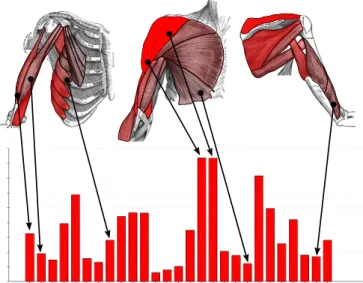
Figure 2. Muscle views (top row) show the activation patterns of muscles. This supports the analysis of theErgonomicsaspect of the data. This visual encoding is clearly more intuitive than the corresponding bar plot shown at the bottom.
their visual encoding is not intuitive and therefore difficult to under-stand. We provide aspect-specific visualizations, which are designed to address:
• theErgonomicsaspect in terms of muscle load,
• and thePhysical Spacein terms of a 3D representation of the movement trajectories and their directions.
4.2.1 Muscle Views
MovExp addresses the specificity of theErgonomicsaspect by pro-viding a new visual encoding that we callmuscle views. It is based on the well-known anatomical illustrations by Henry Gray [26]. This graphical material contains drawings of the human muscles for each part of the body. Each drawing was manually segmented according to the displayed muscles. MovExp draws colors on each muscle to show the aggregated statistics of the activation of the corresponding muscle with respect to the current selection. In order to define a selection, the user can simply click on the muscle. This creates a smooth selection corresponding to the strength of a muscle’s activation.
Note how this visualization method allows to show a high number of variables at once. Figure 2 shows an example of a muscle view that in-tuitively displays 27 variables (muscle activations) in one visualization. The same information is also shown using a bar plot at the bottom of the same figure. The generic bar plot is less intuitive and bears the risk of confusing one muscle for another. It is hard for the user to mentally map a bar to the specific muscle on the body.
We found in practice that the muscle views support the identification of patterns of muscle activations very well.
4.2.2 3D Trajectories Visualization
The actual movement is described in the data set as a 3D trajectory tracking the position of the so-called end-effector. It is typically located at the tip of the finger of the recorded subject.
We render these trajectories as 3D tubes or lines. This addresses the
Physical Spaceaspect of the data. This visualization helps the user to identify the part of 3D space corresponding to the current selection, e.g., to check in which part of the interaction area are the movements with the highest activation.
We did not implement brushing for this 3D visualization. Picking in 3D is difficult due to occlusion. Instead, we provide the ability to create case-specific visualizations that often serve as a two-dimensional substitute for three-dimensional setups (see below).
4.2.3 Circular Directions Visualization
The feedback from our first deployment (see Section 5.1) was that brushing movement directions using generic tools (e.g., scatter plots) is unintuitive and cumbersome.
We developed an aspect-specific visualization method, which in-tuitively shows the directions of each movement in terms of angles on two anatomical planes: coronal and sagittal. We call thisCircular Directions Visualization. It shows a smooth histogram of the tangent directions of the trajectories wrapped around a unit circle. This smooth histogram is obtained using a Gaussian kernel density estimation [52]. Our domain experts found this visualization of high utility for selecting movements with respect to their direction. Examples of this method are shown in Figures 1 and 4a. In Section 5.3 we describe how the HCI experts used this tool to select horizontal movements in order to solve a layout optimization problem.
4.3 Case-Specific Visualizations
Concrete design problems and comparative studies involve user inter-faces with very different 3D egocentric setups. As already mentioned in Section 3.2, these setups are usually given in form of pictures and sketches. We are able to integrate them into the analysis process and to use them as intuitive visualizations of the evaluated user interfaces.
Technically, the domain expert creates a Scalable Vector Graphics (SVG)2by drawing polygons directly on the photo or sketch. These polygons will become active selection and visualization areas later in MovExp. Many tools exist to create such graphics. We use the free software Inkscape [30], where the polygon is annotated with the name of the variable it represents, see Figure 3. For a metric variable, the annotation of the polygon contains just the variable name. For a categorical variable, the annotation contains additionally the value of the desired category.
The SVG graphics can be loaded at runtime into MovExp, where it is displayed using Qt. Since SVG is a variant of XML, we can easily traverse the XML tree to find the annotated polygons, change their color and opacity according to the current selection, and finally feed the altered XML to Qt for display.
For metric variables, the polygon opacity displays the arithmetic mean of the corresponding variable with respect to the current selection. Other statistical measures such as variance can be shown as well. For categorical variables, the situation is slightly different. The polygon shows only information corresponding to the defined category, i.e., a specific target in the setup. The polygon opacity is again determined by the statistics of a metric variable, i.e., the average accuracy of all movements to that target. This metric variable is chosen within MovExp. The RGB color of the polygon identifies the current selection within MovExp.
To support brushing on case-specific visualizations, the user can simply click on the respective polygons. This creates a corresponding selection. See Figure 6 for an example.
The domain experts found case-specific visualizations especially useful for HCI case studies with very short turnaround times of a few days. In those cases, the effort of programming a new visualization widget in C++ is too high, but the SVG-based solution leads to intuitive results in a short time. Such a case study is reported in Section 5.3. Our domain experts exploited this capability also for a summarization task (Section 5.5).
5 DEPLOYMENT: USAGESCENARIO ANDCASESTUDIES
We study the applicability of our visualization tool by presenting one usage scenario and three case studies,3each of them covering one of the four broad visualization tasks from Section 3.1. We start with an overview of the deployment history.
2SVG is a variant of XML for describing 2D graphics. Both bitmaps and vector graphics can be used in an SVG file.
3We follow Sedlmair et al. [51] in their use of the termsusage scenarioand case study, where the former is executed by visualization experts and the latter is executed by the domain scientists.
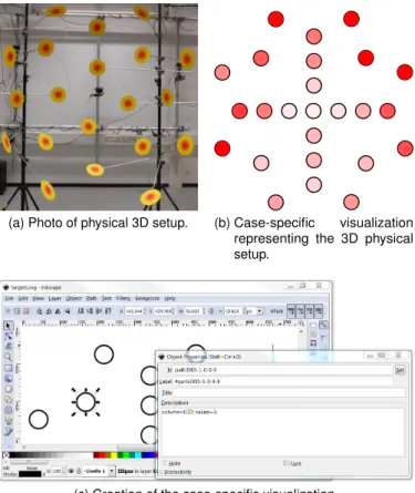
(a) Photo of physical 3D setup. (b) Case-specific visualization representing the 3D physical setup.
(c) Creation of the case-specific visualization.
Figure 3. Example of definition of a case-specific visualization. Starting from a photo of the physical setup used in the HCI case study, the domain expert draws a corresponding 2D sketch. The polygons are annotated to relate them to variables in the data set. The resulting visualization shows the average accuracy for movements starting from the respective targets – fully integrated into the Linking & Brushing environment.
5.1 Deployment History
MovExp and its features were iteratively developed with the HCI ex-perts over the period of two years. At the outset of this collaboration, the HCI experts had already collected a limited data set. Our HCI experts are two researchers who are also co-authors of this paper (A. Oulasvirta and M. Bachynskyi). A. Oulasvirta is a cognitive scientist and group leader at our institute and M. Bachynskyi started as his Ph.D. student. A. Oulasvirta has worked in HCI for ten years, mostly in modeling and studying human factors of novel interactive technologies, but he had not worked on biomechanical simulation prior to meeting M. Bachynskyi. At the time they started working together, motion capture based biomechanical simulation was not used in HCI although it carried obvious benefits. They developed a methodology that allowed intertwining it with the laboratory paradigm of HCI that was usabil-ity and performance-focused. Visualization was a major bottleneck in their work. Prior to collaboration with the visualization experts (G. Palmas and T. Weinkauf), they used Matlab for preselecting data (e.g., according to muscles or 3D location) and then static 2D graphs for visualization. The collaboration started with questions focusing on visualization, but because of the importance of visualization, the collaboration got deeper. Eventually all papers were jointly authored.
The development of MovExp was started by the PhD student G. Pal-mas who reported twice a week a “VisInsight” – a small report about a finding in the data obtained with the latest version of the software. The earliest analyses served two purposes: technical validation of the data and exploration of the known human factors reported in motor control research. These regular reports strengthened the collaboration and provided impetus for the development. We report some of the gained insights from this usage scenario in Section 5.2.
(a) Brushing movement directions using a scatter plot.
All Bottom-Up Top-Down
(b) Average absolute velocity of brushed movements.
Figure 4. Top-down (blue) pointing movements are slower than bottom-up (red) movements. This was a surprising outcome of our analysis regarding basic human factors. Compare with Figure 5.
Figure 5. Brushing directions on a circular directions visualization has proven more intuitive than brushing them using generic tools. Compare with Figure 4a.
The first actual case studyin the wildtook place with a large data set of 3D in-air pointing [11]. Several months of work of the HCI experts went into motion capture, preprocessing, and biomechanical simulation.
The visualization tool contained with the muscle view and the 3D trajectory visualization the first aspect-specific visualization methods. They proved very useful. So did a case-specific visualization showing a simplified 2D sketch of the actual 3D user interface. Two shortcomings were revealed in this case study. First, due to the size of the data set, the VTK implementation of parallel coordinates was reported to be painstakingly slow. We addressed this first by re-implementing it using vertex buffer objects on the GPU, but the HCI experts were not satisfied with the sometimes still sluggish responsiveness for their larger data sets. We eventually ended up developing a new derivative of parallel coordinates; recently presented at a conference [47]. The second shortcoming was that movement directions had to be specified with generic tools such as scatter plots, which was reported to be unintuitive and cumbersome. It led us to introduce a new aspect-specific visualization: a circular widget for brushing and visualizing directions (see Section 4.2).
The second version of MovExp was deployed in seven HCI case studies. Some of them had short turn-around times of a few days, while others took several weeks to complete. We report three of them in Sections 5.3 – 5.5. Throughout the cases, the HCI experts made heavy use of the aspect-specific views and case-specific visualizations. In fact, they even exploited the case-specific visualization feature to create a summative muscle view (Section 5.5).
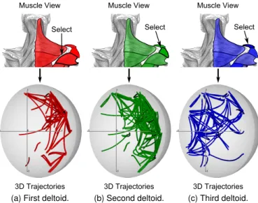
Select Muscle View
3D Trajectories
(a) First deltoid.
Muscle View 3D Trajectories Select (b) Second deltoid. Select Muscle View 3D Trajectories (c) Third deltoid.
Figure 6. The user clicks directly on a muscle in the muscle view, which creates a smooth selection corresponding to its activation. The 3D trajectory visualization reveals the spatial pattern for which this muscle is recruited the most.
5.2 Usage Scenario: Understanding 3D Aimed Move-ments
In order to familiarize ourselves with the domain, we performed analy-ses for the HCI experts in the beginning stage of our collaboration. We reported our findings twice a week. These analyses were primed by discussions where the HCI experts explained their interests. Their first data set was from a study of rapid aimed movements performed repeatedly between targets in 3D space. The targets were distributed over a half-sphere with radius equal to the subject’s arm length and centered at the right shoulder’s pivot point.
Our first success in using MovExp came from an analysis of move-ment velocities. Figure 4 shows that top-down pointing movemove-ments are slower than bottom-up movements. The HCI experts were surprised to learn this fact, because one would assume that working against gravity makes a movement slower. After checking for possible errors in the data, of which there were none, they later came to the conclusion that gravity actually helps the subject in controlling the deceleration phase of the bottom-up movements. The subject was asked to point with the index finger to a target as quickly and accurately as possible.
At the time, we used scatter plots to brush movement directions (Figure 4a). Later we developed the more intuitive circular directions visualization as shown in Figure 5.
Another insight came from the analysis of aimed movements in 3D space against muscle activation. This was the first use of the muscle view. Figure 6 shows how we used it to select muscles by simply clicking on them. The associated 3D movements are shown in the trajectories visualization. Note that this is an example for the utility of the smooth selections: when selecting a muscle, all movements are selected with the strength of this muscle’s activation during that movement. Hence, only those movements are highlighted for which the muscle is actually recruited the most. In this exercise, we focused on the three deltoid muscles, which are important in arm movements. For the HCI experts, it was interesting to learn how differently the three deltoids are recruited for movements in the 3D space.
Figure 7 provides a walkthrough of a typical analysis session in MovExp. The goal is to design a fitness game focused on training the back muscles. These muscles were selected directly on a muscle view (Figure 7a). The identified movements involve a high recruitment of all the back muscles (andoperator). The circular direction visualization (Figure 7b) clearly shows that most of the involved movements have a slightly diagonal direction. All other movements were discarded using this widget. The case-specific visualization in Figure 7c shows a sketch
b) Selecting directions Select Select Select Select Select Select Select
(a) Selecting muscles (c) Selecting areas (d) Visualizing trajectories Figure 7. Design of a fitness game focused on training the back muscles. First, the muscles on the back are selected, which shall be trained by playing the game. The involved directions and areas can be seen in the aspect- and case-specific visualizations in (b) and (c). Selecting the most dominant directions and areas reveals two distinguished performance areas in 3D space, shown in (d).
of the physical setup. It can be seen that only few remaining movements are contained in the central part. They were discarded using this widget by selecting the outer areas. A finalandcombination between all selections gives the resulting trajectories shown in Figure 7d. This result provides ergonomically justified suggestions to a designer: the fitness game should mostly involve movements concentrated on the left and/or the right part of the egocentric space. These movements recruit the back muscles as desired.
5.3 Case: Optimal Input Regions on a Public Display
The HCI experts were interested in identifying optimal input regions for interfaces controlled by arm movements. By optimality, they referred to input regions with highest performance and lowest ergonomic costs. One case was a public display. These interactive surfaces often require keeping the arm extended during interaction, i.e., the ergonomics are of great interest here. Their analysis was focused on horizontal input regions (strips). The data set came from recordings of a male subject selecting targets on the display. Figure 1 shows the setup.
The circular directions visualization allowed selecting movements that correspond to horizontal input regions. The optimality constraint was brushed on a scatter plot showing muscle activation against through-put (Figure 1). The two selections were combined using theand opera-tor of MovExp. The outcome was shown on a intuitive case-specific visualization where a photo of the public display and some circles were combined to show the input regions.
The optimal region was identified to be in the middle of the display. In this region, the mean movement inaccuracy is 17mm and the mean interaction throughput is 13.8bits/s. Also, the index of energy expendi-ture, which is activation of all muscles integrated over movement, is 145.6 abstract units. By contrast, the movements in the non-optimal region are 19.2% less accurate (mean inaccuracy 20.5mm) and as re-sult the mean interaction throughput is 1.5 bits/s lower (12.3bits/s). The energy expenditure difference is more dramatic and shows 200.9 abstract units, which is 39% higher comparing to the optimal region. In summary, the interaction in the optimal region is faster and less energy-demanding.
The result confirmed the experts’ hypothesis that placing frequently used buttons on the top of the display is detrimental. The implication was to either lower the display or place the buttons in the middle part to the left and right sides of the content view.
The entire process of recording the movements, preprocessing the data, and analyzing it together with the specification of the case-specific visualization was completed within a workday. The domain experts need MovExp to integrate seamlessly into their pipeline and to enable fast analyses. This was one of the studies where this was proven.
(a) Steering Wheel. (b) Bird. (c) Arm Flexor.
Figure 8. MovExp was used to compare three interaction paradigms for plane control: Steering wheel, bird and arm flexor. The muscle views show clearly the different amount of activation involved by the three paradigms. The Steering Wheel was selected as the best choice for plane control.
5.4 Case: Comparison of Continuous Full-Body Controls
A recurring interest in empirical HCI is the comparison of alternative designs. Our HCI experts were interested in comparing different meth-ods for controlling a plane in a flight simulator: 1) the bird, where arms are extended to the side, 2) the steering wheel, where arms are extended and rotate for control, and 3) the arm flexor, where the right arm is lowered and flexed. They wanted to identify the least fatiguing method. Due to the high number of muscles, comparing their respective activations using a line plot or a bar plot would be too slow and unintu-itive. The muscle views immediately conveyed stark differences of the muscle activations. Figure 8 shows them rendered for each condition. The HCI experts identified thesteering wheelas the best method. It recruited mostly the muscles of the lower body together with some postural muscles and the muscles of the neck. This includes thegluteus
muscles as well as thegracilis,splenius capitisandlevator scapularis. By contrast, the bird recruited the stronger muscles of the upper back, shoulder, chest and arm. This includes the deltoids, infraspinatus,
pectoralis major,biceps,brachialisandserratus anterior. All the other muscles were recruited moderately in a similar way in both of the cases. While the absolute difference between the two sums of activations of all muscles is quite small, the general effect of the differences is significant. In fact, the lower body and the postural muscles usually contain a higher percentage of fatigue-resistant fibers than the upper body muscles. This is beneficial for the steering wheel, where the lower body muscles do not get fatigued as fast as the upper body muscles in the bird case.
5.5 Case: Summarization of Movement Data
HCI researchers often need to represent findings from empirical studies in a way that can inform constructive efforts. This places a demand for visually summarizing main tendencies in a data set. Such summaries can be used in design efforts almost like a “check list.”
In this case, our HCI experts were interested in summarizing 3D pointing movements as “equivalence classes“ based on similarities in muscle coactivation patterns. Their clustering concerns the time-dependent activation signal of 41 muscles of the upper extremities in pointing movements. Using hierarchical clustering, they had pre-clustered muscle coactivation patterns from OpenSim into 11 distinct clusters. Their aim was to use such clusters as a checklist when making decisions on where to place interactions in users’ ego-centric space.
The visualization task was to provide an overview of the activation patterns of the muscles in each cluster. The patterns are complex,
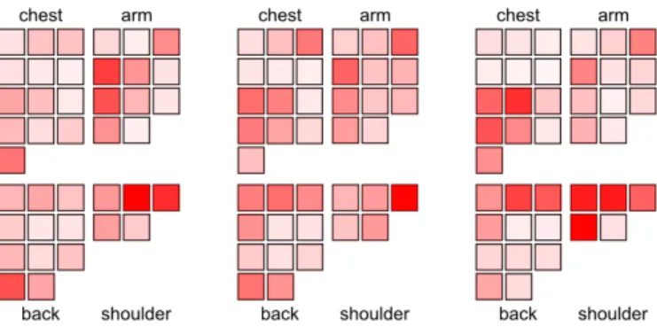
Figure 9. HCI experts clustered their data set according to muscular coactivation patterns in 3D pointing movements. Their interest was to have an overview of the different activations of the muscles of each cluster. They exploited the SVG-based solution – originally intended for case-specific visualizations – to create a simplified LED-like display where each muscle was mapped to a small square. The squares were then grouped according to their respective body parts. Here we show ex-amples of three clusters out of their eleven. Each cluster is characterized by a unique distribution of muscle activations that can now be visually examined.
consisting of frame level and aggregated data for 41 muscles. They used the SVG-based solution for case-specific visualizations to create a new kind of muscle view, which allowed them to map activation in each muscle to a small LED-like square. The different squares were then grouped according to the area of the body of the respective muscle. The adjacency relation of human muscles was preserved in this visualization: close muscles in the real human body are represented accordingly as close squares. The opacity of a square shows the average muscle activation. This allowed to clearly view the different patterns of each equivalence class in a concise way. Figure 9 shows the outcome. The cluster with the least muscle activations turned out to be in the central and lower part of space in the middle front-to-right side of the body. The movements within this cluster are produced by moderately activated muscles of the shoulder, the back and the arm. By contrast, the cluster in the upper part of space contains movements produced by high activations of the front and sidedeltoidstogether with the
trapezius. The cluster in the left part of space contains movements produced by high activation of the frontdeltoid and thepectoralis major. For many scenarios in human-computer interaction, the cluster with moderate activations is better suited than the other clusters, since it allows a low-fatiguing interaction for a prolonged time.
6 CONCLUSIONS ANDFUTUREWORK
We presented the visualization software MovExp, which helps HCI experts to analyze data sets from the recently introduced mocap-based biomechanical simulation approach. With the support of our analysis tool, the domain experts can evaluate user interfaces regarding perfor-mance and ergonomics. A usage scenario and three case studies attest the usefulness of our tool.
Our present collaboration partners represent a subset of potential interests. We see many possibilities to extend the applicability of MovExp [16]. Beyond novel input methods, HCI groups work on many topics of emerging technologies where human movement needs to be understood, such as ubiquitous and mobile computing, mixed reality, tangible computing, and natural user interfaces. In addition, human factors groups study changes in physical ergonomics triggered by new technologies on “traditional” contexts such as workplaces and cars. These groups have slightly varying analysis needs and data types, but the topics are close enough to warrant an extension in this direction.
On a more technical level, a larger proportion of HCI researchers can benefit from our work, if the following challenges are addressed. HCI researchers are routinely analyzing events during interaction to explain the observed outcomes. Hence, the interactionprocessrequires
adequate support in our visualization tool. This also includes support for the temporal domain. One of the main challenges in this regard is the extension of case-specific views to support dynamically changing environments, such as in virtual reality or games where users move around. Whereas our analyses focused on a single end-effector, some-times the wholepostureof the user must be considered. Consider for example the analysis of postures in the use of tablet devices, or the use of articulated hand tracking where several degrees of freedom are simultaneously used in control.
We presently looked at cases with only one user. Future development will include support for user groups. The generic functionality readily extends to this. It will also be straightforward to incorporate other often-used data types for outcome metrics, such as satisfaction and other widely used questionnaire-based metrics. However, a challenge for the aspect-specific views (e.g., muscle view) will be to express variability among users instead of point averages.
REFERENCES
[1] PhaseSpace Impulse, PhaseSpace, http://www.phasespace.com/. [2] Noraxon Clinical DTS, http://www.noraxon.com/emg/clinical/clinical-dts. [3] University of Oregon HCI Research Laboratory. Win-Fitts: Two-dimensional Fitts experiments on Win32, http://www.cs.uoregon.edu/research/hci/research/winfitts.html. [4] Motion Builder, Autodesk, http://www.autodesk.com.
[5] Recap2, PhaseSpace, http://www.phasespace.com/software.html. [6] Motive, OptiTrack, https://www.naturalpoint.com/.
[7] JACK, Siemens, https://www.plm.automation.siemens.com/.
[8] W. Aigner, S. Miksch, H. Schumann, and C. Tominski.Visualization of time-oriented data. Springer, 2011.
[9] G. Andrienko, N. Andrienko, P. Bak, D. A. Keim, and S. Wrobel.Visual Analytics of Movement. Springer, 2013.
[10] M. Bachynskyi, A. Oulasvirta, G. Palmas, and T. Weinkauf. Biomechani-cal simulation in the analysis of aimed movements. InExtended Abstracts (Works in Progress) CHI’13, pages 1–6, Paris, France, April 2013. ACM. [11] M. Bachynskyi, A. Oulasvirta, G. Palmas, and T. Weinkauf. Is motion capture-based biomechanical simulation valid for hci studies? study and implications. InProc. ACM CHI Conference on Human Factors in Com-puting Systems, pages 3215–3224, Toronto, Canada, April 2014. [12] G. Bailly, A. Oulasvirta, T. Kötzing, and S. Hoppe. Menuoptimizer:
Interactive optimization of menu systems. InProceedings of the 26th annual ACM symposium on User interface software and technology, pages 331–342. ACM, 2013.
[13] P. Bazeley and K. Jackson.Qualitative data analysis with NVivo. Sage Publications Limited, 2013.
[14] R. Becker and W. Cleveland. Brushing scatterplots. Technometrics, 29(2):127–142, 1987.
[15] BIOMEC Inc.Operator’s Manual for ACUPATH Lumbar Motion Monitor with Ballet Software, 1.2 edition, 10 2002.
[16] S. Carpendale. Evaluating information visualizations. InInformation Visualization, pages 19–45. Springer, 2008.
[17] D. Colombini. Risk Assessment and Management of Repetitive Move-ments and Exertions of Upper Limbs: Job Analysis, Ocra Risk Indicies, Prevention Strategies and Design Principles. Elsevier, 2002.
[18] C. J. Cook and K. Kothiyal. Influence of mouse position on muscular activ-ity in the neck, shoulder and arm in computer users.Applied Ergonomics, 29(6):439–443, 1998.
[19] A. Cooper and L. Straker. Mouse versus keyboard use: A comparison of shoulder muscle load.Industrial Ergonomics, 22(4):351 – 357, 1998. [20] M. Damsgaard, J. Rasmussen, S. T. Christensen, E. Surma, and M. de Zee.
Analysis of musculoskeletal systems in the anybody modeling system. Simulation Modelling Practice and Theory, 14(8):1100–1111, 2006. [21] S. L. Delp, F. C. Anderson, A. S. Arnold, P. Loan, A. Habib, et al.
Open-Sim: Open-source software to create and analyze dynamic simulations of movement.IEEE Trans. Biomedical Engineering, 54(11):1940–1950, 2007.
[22] H. Doleisch, M. Gasser, and H. Hauser. Interactive feature specification for focus+context visualization of complex simulation data. InProc. VisSym 03, pages 239–248, 2003.
[23] J. Du and V. G. Duffy. A methodology for assessing industrial worksta-tions using optical motion capture integrated with digital human models. Occupational Ergonomics, 7(1):11–25, 2007.
[24] G. Ellis and A. Dix. An explorative analysis of user evaluation studies in information visualisation. InProceedings of the 2006 AVI workshop on BEyond time and errors: novel evaluation methods for information visualization, pages 1–7. ACM, 2006.
[25] B. W. Epps. Comparison of six cursor control devices based on fitts’ law models. InProceedings of the Human Factors and Ergonomics Society Annual Meeting, volume 30, pages 327–331. SAGE Publications, 1986. [26] H. Gray.Anatomy: Descriptive and Surgical. Lea & Febiger, Philadelphia,
1918. Bartleby.com, 2000.
[27] E. Haider, H. Luczak, and W. Rohmert. Ergonomics investigations of work-places in a police command-control centre equipped with tv displays. Applied ergonomics, 13(3):163–170, 1982.
[28] K. R. S. Holzbaur, W. M. Murray, and S. L. Delp. A model of the upper extremity for simulating musculoskeletal surgery and analyzing neuromuscular control.Ann. of Biomed. Eng., 33:829–840, 2005. [29] H. Honglun, S. Shouqian, and P. Yunhe. Research on virtual human in
ergonomic simulation.Computers & Industrial Engineering, 53(2):350 – 356, 2007. Selected Papers from The 27th. International Conference on Computers & Industrial Engineering - Part 2.
[30] Inkscape Team, Inkscape. Draw Freely, http://www.inkscape.org/. [31] D. F. Keefe, M. Ewert, W. Ribarsky, and R. Chang. Interactive coordinated
multiple-view visualization of biomechanical motion data.IEEE TVCG, 15(6):1383–1390, 2009.
[32] D. A. Keim. Information visualization and visual data mining. IEEE TVCG, 8(1):1–8, 2002.
[33] M. Kipp. Anvil: A universal video research tool.J. Durand, U. Gut, G. Kristofferson (Hrsg.) Handbook of Corpus Phonology, Oxford University Press.
[34] U. Kuckartz. Maxqda: Qualitative data analysis.Berlin: VERBI software, 2007.
[35] H. Lam, E. Bertini, P. Isenberg, C. Plaisant, and S. Carpendale. Empirical studies in information visualization: Seven scenarios.Visualization and Computer Graphics, IEEE Transactions on, 18(9):1520–1536, 2012. [36] B. Lee, P. Isenberg, N. Riche, and S. Carpendale. Beyond mouse and
keyboard: Expanding design considerations for information visualization interactions.Visualization and Computer Graphics, IEEE Transactions on, 18(12):2689–2698, Dec 2012.
[37] M. F. Machado, P. Flores, J. Walter, and B. Fregly. Challenges in using OpenSim as a multibody design tool to model, simulate, and analyze pros-thetic devices: a knee joint case-study. http://hdl.handle.net/1822/19411, 2012.
[38] I. S. MacKenzie, A. Sellen, and W. Buxton. A comparison of input devices in elemental pointing and dragging tasks. InProceedings of ACM CHI 91 Conference on Human Factors in Computing Systems, pages 161–166, 1991.
[39] S. I. MacKenzie. Fitts’ law as a research and design tool in human-computer interaction.Human-computer interaction, 7(1):91–139, 1992. [40] K. Matkovic, W. Freiler, D. Gracanin, and H. Hauser. Comvis: A
coordi-nated multiple views system for prototyping new visualization technology. InInformation Visualisation, 2008. IV’08. 12th International Conference, pages 215–220. IEEE, 2008.
[41] J. Miehling, D. Krüger, and S. Wartzack. Simulation in human-centered design–past, present and tomorrow. InSmart Product Engineering, pages 643–652. Springer, 2013.
[42] T. Muhr. Atlas/ti–a prototype for the support of text interpretation. Quali-tative sociology, 14(4):349–371, 1991.
[43] C. Müller, L. Tomatis, and T. Läubli. Muscular load and performance com-pared between a pen and a computer mouse as input devices.International Journal of Industrial Ergonomics, 40(6):607 – 617, 2010.
[44] C. J. Murchie and G. N. Kenny. Comparison of keyboard, light pen and voice recognition as methods of data input.International journal of clinical monitoring and computing, 5(4):243–246, 1988.
[45] L. P. Noldus, R. J. Trienes, A. H. Hendriksen, H. Jansen, and R. G. Jansen. The observer video-pro: New software for the collection, management, and presentation of time-structured data from videotapes and digital media files.Behavior Research Methods, Instruments, & Computers, 32(1):197– 206, 2000.
[46] A. Oulasvirta, A. Reichel, W. Li, Y. Zhang, M. Bachynskyi, K. Vertanen, and P. O. Kristensson. Improving two-thumb text entry on touchscreen devices. InProceedings of the SIGCHI Conference on Human Factors in Computing Systems, pages 2765–2774. ACM, 2013.
[47] G. Palmas, M. Bachynskyi, A. Oulasvirta, H.-P. Seidel, and T. Weinkauf. An edge-bundling layout for interactive parallel coordinates. InProc.
IEEE PacificVis, Yokohama, Japan, March 2014.
[48] J. A. Reinbolt, A. Seth, and S. L. Delp. Simulation of human movement: applications using opensim.Procedia IUTAM, 2(0):186 – 198, 2011. [49] J. C. Roberts. State of the art: Coordinated & multiple views in exploratory
visualization. InProc. Coordinated and Multiple Views in Exploratory Visualization, pages 61–71. IEEE, 2007.
[50] W. Schroeder, K. Martin, and B. Lorensen.VTK Textbook. Kitware, Inc, 2006.
[51] M. Sedlmair, M. Meyer, and T. Munzner. Design study methodology: Reflections from the trenches and the stacks.IEEE TVCG, 18(12):2431– 2440, 2012.
[52] B. Silverman.Density Estimation for Statistics and Data Analysis. Chap-man & Hall/CRC, 1986.
[53] R. W. Soukoreff and I. S. MacKenzie. Generalized fitts’ law model builder. InConference companion on Human factors in computing systems, pages 113–114. ACM, 1995.
[54] TIBCO Spotfire, http://spotfire.tibco.com/.
[55] C. Stolte, D. Tang, and P. Hanrahan. Polaris: A system for query, analysis, and visualization of multidimensional relational databases.IEEE TVCG, 8(1):52–65, 2002.
[56] D. F. Swayne, D. Cook, and A. Buja. Xgobi: Interactive dynamic data visualization in the x window system. Journal of Computational and Graphical Statistics, 7(1):113–130, 1998.
[57] Tableau Software, http://www.tableausoftware.com/.
[58] P. van der Meulen and A. Seidl. Ramsis–the leading cad tool for ergonomic analysis of vehicles. InDigital Human Modeling, pages 1008–1017. Springer, 2007.
[59] A. Veloso, G. Esteves, S. Silva, C. Ferreira, and F. Brandão. Biomechan-ics modeling of human musculoskeletal system using adams multibody dynamics package. InProceedings of the 24th IASTED International Conference on Biomedical Engineering, Innsbruck, pages 401–407, 2006. [60] M. O. Ward. Xmdvtool: Integrating multiple methods for visualizing multivariate data. InProc. IEEE Visualization, pages 326–333. IEEE Computer Society Press, 1994.
[61] C. Weaver. Building highly-coordinated visualizations in Improvise. In Proc. InfoVis, pages 159–166. IEEE, 2004.
[62] T. G. Whisenand and H. H. Emurian. Analysis of cursor movements with a mouse.Computers in Human Behavior, 15(1):85–103, 1999. [63] P. C. Wong and R. D. Bergeron. 30 years of multidimensional multivariate
visualization. InScientific Visualization, Overviews, Methodologies, and Techniques, Dagstuhl, Germany, pages 3–33, 1994.
[64] M. YANG and M.-d. YIN. Ergonomics simulation and application in vir-tual assembly based on delmia.Agricultural Development & Equipments, 7:005, 2009.
![Table 1. Output variables produced by mocap-based biomechanical simulation. Count is based on simulations with the SIMM Full Body Model [28] and represents the cardinality of each variable](https://thumb-us.123doks.com/thumbv2/123dok_us/9500821.2825779/4.918.66.441.75.465/variables-produced-biomechanical-simulation-simulations-represents-cardinality-variable.webp)