Abstract—This paper presents the design and development of an automatic automobile headlight switching system. Headlights of vehicles are inherent for night driving. These bright headlights which assist the driver for vision, while driving at night, pose a great threat to the other road users coming in the opposite direction. The bright light of the vehicles causes a discomfort in the form of a glare to the oncoming driver. As a rule in night driving, every driver is expected to switch their headlights from high beam to low beam once they spot an oncoming vehicle within 150 metres in order to reduce the glare, but this practice is hardly adhered to. This is one of the major causes of accidents during the night, as the opposing driver will not be able to see the road clearly due to the brightness of the oncoming vehicle's lights. This automatic headlight switching system switches the high beam lamp to low beam as soon as it senses a vehicle approaching from the opposite direction and switches it back to high beam when the cars pass each other. The prototype is an electronic circuit that incorporates the use of a 12 volts power supply which is provided by the car battery itself, a light dependent resistor which acts as the sensor, a potential divider network which serves as a comparator to trigger an NPN transistor connected to an SPDT relay which does the switching. It was designed, constructed, tested and it worked, sensing to a distance of 147 metres. This design minimizes night accidents occurring as a result of this glare by the introduction of automatic headlight control in automobiles. This solves the problem of switching which is not done most of the time, reduces the stress of continuously switching beams manually, hence giving the driver more concentration on the road while driving at night. This paper brings to limelight the need for manufacturers of automobiles to inculcate this in modern cars to improve on the deficiency of the existing ones.
Index Terms— automatic headlight switching, Dimmer, Troxler Effect, Luminous Intensity, Lumens,
I. INTRODUCTION
The requirement of headlight is a necessity during night travel. The same headlight which assists the driver for better vision during night travel is also responsible for many accidents. The driver has the control of the headlight which can be switched from high beam (bright) to low beam (dim). During pitch black conditions where there are no other sources of light, high beam is used while on all other cases, low beam is preferred. In a two-way traffic, vehicles ply on both sides of the road, so when the bright light from the headlight of a vehicle coming from the opposite direction
Manuscript received.
O. Akinsanmi, Department of Electrical and Electronics Engineering, Federal University Oye-Ekiti, Ekiti State, Nigeria, +2348068108694, (e-mail: [email protected] ).,[email protected]
A. D. Ganjang, Department of Electrical and Computer Engineering, Ahmadu Bello University, (ABU), Zaria, Nigeria, (e-mail: [email protected] )
H. U. Ezea, Department of Electrical and Electronics Engineering, Federal University Oye-Ekiti, Ekiti State, Nigeria, +2348030889118, (e-mail: [email protected] )
falls on a person, it glares him for a certain amount of time, causing disorientation to that driver. This discomfort will result in momentary involuntary closing of the driver’s eyes. This fraction of distraction is the prime cause of many road accidents at night. This prototype reduces this problem by actually switching the bright headlight of the vehicle to low beam automatically when it senses a vehicle at close proximity approaching from the other direction and switching it back after the vehicle passes. The entire working of the dimmer is an electronic circuitry arrangement which senses and switches the headlight according to the required conditions.
II. PROBLEMSTATEMENT
Road accidents occur every day with the higher percentage of occurrences at night. This is because visibility at night is not as good as that at the day time. The importance of bright driving lights to a vehicle has as much an opposite effect on the opposing vehicle, hence the need to reduce that effect. Drivers are human and tend to forget to switch the beams, which is a task that has to be done over and over, and this can be tiring. When our eyes are exposed to a very bright source of light, around 1000 lumens, we experience a glare. This glare is produced due to over exposure of the rods and cones inside our eye. Even after the source of glare is removed, an after-image remains in our eye that creates a blind spot. This phenomenon is called the Troxler effect [2]. The Troxler effect increases driver reaction time by up to 1.4 seconds. This means that when traveling at 100 km/h, it would take the driver 37.5meters to see and react to road hazards [3].
III. MATERIALSANDMETHODOLOGY
The circuit consists of a dc power supply, resistors, a transistor, diodes, a relay, switches, a light dependent resistor and LEDs. The circuit was designed from the relationships of these components to obtain the desired behaviour. Logical steps where followed in the design and construction of this project for optimum performance. The considerations followed are described below;
i. The effects of high illumination on the human eye and response delay
ii. Luminous intensity of headlamps
iii. The selection of components to be used for the effective switching of beams
iv. The sensitivity of components to reduce the switching time
v. The power supply unit
vi. Protection of the module against electrical and environmental hazards
vii.
Backup plan in case of module failureDesign and Development of an Automatic
Automobile Headlight Switching System
IV. DESIGN AND ANALYSIS
i. Power Supply: This block provides the voltage needed for the comparison, processing, switching and the output.
ii. Sensor: The sensor is a component that responds to light, in this case a light dependent resistor. It senses both the presence and absence of light at different intensities which changes the values of its resistance. iii. Comparator: The comparator is the resistor arrangement which serves as a potential divider that control the gate current to the transistor.
iv. Switching Unit: This is the block that performs the switching function. It consists of the transistor and relay. The current that the transistor receives from the comparator switches the relay on and off.
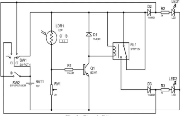
v. Output: The output is two Light emitting diodes connected to the relay. The lights alternate based on the behaviour of the entire system. The output shows the performance of the intended purpose of the circuit, which is switching the high beam to low beam to prevent the glare on the approaching vehicle. The prototype was carefully implemented on the structure presented in the block diagram in fig.1 Components were carefully selected with the intended purpose in mind. It is necessary to note that for the full eradication of the troxler effect on night driving, the dimmer is to be integrated on all vehicles so that the dimming benefits all road users at the same time. Also, the design is a prototype, therefore some parameters such as size and light intensities are considered at a reduced scale.
Fig 1: Circuit Diagram
Principle of operation
From the layout given if Fig. 1, the basic idea about the working of the circuit can be understood. This can be discussed below:
A. The Light Dependent Resistor
The LDR acts as a variable resistor. So the LDR and the two resistors form a potential divider network which will decide the current in the circuit. In pitch black situations, its resistance is very high. The circuit is balanced and a very negligible current flows to the transistor. This current is not sufficient to activate the transistor.
The measured resistance value of the LDR at night darkness is at Supply voltage
where is base current in darkness
This current is not sufficient to activate the BJT.
On the other hand, considering when a light source of about 800 lumens falls on the Light Dependent Resistor.
The measured resistance value of the LDR with light is about 1kΩ = 103Ω Supply voltage = 12V
where is base current in light.
This current causes an imbalance in the circuit which triggers the transistor.
B. Resistors R1 and RV1
The resistors combined with the light dependent resistor form the potential divider network. They are used as a potential divider in order to control the base current to the transistor. The RV1 is a variable resistor of 2kΩ. Varying this potentiometer increases or decreases the current going into the base of the transistor, which varies the sensitivity of the switching circuit. We can say that the two resistors depend on the LDR since no current flows into the loop in the dark.
Fig 2: Potential Divider Network
From the above network,
(
)
Where VRB = Transistor base resistor voltage V = Supply voltage = 12V RB= base resistance = 33Ω RIN = LDR input resistance = 1000Ω Hence, ( ) OR
C. The transistor (BC547)
The transistor is an NPN silicon transistor. It is used as a operated in the saturated region which sets the circuit on. The transistor terminals require a fixed DC voltage to operate in the desired region of its characteristic curves. This is known as the biasing. For amplification applications, the transistor is biased such that it is partly on for all input conditions. The input signal at base is amplified and taken at the emitter. BC547 is used in common emitter configuration for amplifiers. The voltage divider is the commonly used biasing mode. For switching applications, transistor is biased so that it remains fully on if there is a signal at its base. In the absence of base signal, it gets completely off [4].
The transistor in the circuit is used as a switching sensor. The current at the base from when light is applied to the LDR turns it on and it stays on till the LDR loses illumination.
D. The Relay
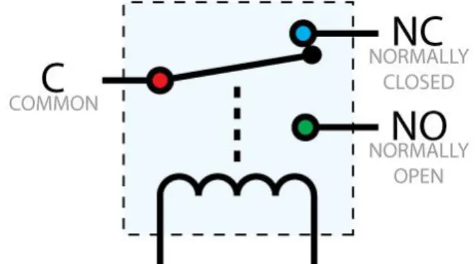
After the transistor is triggered, the current that flows through the collector goes into the coil of the 12V Single Pole Double Throw Relay. The relay in its default position is in the normally closed (NC) state. This current that flows through the coil causes an electromagnetic induction which disconnects the relay from the normally closed terminal to the normally open (NO) terminal. The relay contacts stays in that position till the transistor current is cut off, which will be due to the absence of light to the Light Dependent Resistor.
When the trigger current from the transistor is cut off, the relay mechanically switches back to its initial (normal) position.
Fig 3: Relay Switching Contacts and terminals Source:(Wikipedia.com)
As the relay deactivates, energy is generated from the collapsing magnetic field which will tend to move in the reverse direction towards the transistor. This current will cause damage to the transistor; hence a diode is connected across the relay to dissipate the collapsing magnetic field energy [5].
E. The Diode
The most common function of a diode is to allow an electric current to pass in one direction (called the diode'sforwarddirection), while blocking current in the opposite direction (thereversedirection). Thus, the diode can be viewed as an electronic version of a check valve. As the relay coil is energized with DC, a diode is installed across the coil to dissipate the energy from the collapsing magnetic field at deactivation, which would otherwise
generate a spike of voltage and might cause damage to circuit components. This diode can be seen as a freewheel diode. The diode chosen for this function is the 1N4001 as it can handle up to 1A efficiently [7].
F. LED's
The LED's used in the prototype represent the actual high and low beams. LED 1 (The white LED) represents the high beam light and is connected to Normally Closed (NC) terminal of the relay. When the switch is closed in the dark, the high resistance of the Light Dependent Resistor prevents current from going through the transistor so the high beam LED displays and stays on.
On the other hand, LED 2 (Red LED) is the low beam light. It is connected to the Normally Open terminal of the relay which depends on the resistance of the Light Dependent Resistor and the potential divider network. It is switched on when light is incident on the LDR and current flows to the BJT.
The entire operation of the circuit can be integrated and summarized below: The basic operation is like that of a comparator. The transistor’s output is connected to the relay coil. The bulbs are already connected to the relay contacts as mentioned earlier. LED 1 represents the high beam bulb which is in normally closed (NC) condition with the relay. LED 2 represents the low beam bulb of the vehicle which is at the normally open terminal (NO) of the relay. Whenever a high-intense light falls on the LDR, the resistance drops thus creating an unbalance in the potential divider formed between the LDR, and two resistors R1 and R2. This will create a trigger current which turns on the transistor BC 547. The transistor gets into conduction mode and switches the relay. Hence the NC terminal will get disconnected and NO terminal will be switched. So, the vehicle’s headlight which is in bright mode (LED 1) gets turned off and the low beam mode (LED 2) gets turned on by the relay. This happens when the vehicle from the opposite side crosses our vehicle. Thus as the other vehicle comes nearer, the intensity of that beam will increase and will hence switch our high beam light to low beam. As it moves away, the LDR will be turned away from the moving vehicle. So the LDR resistance increases and the bridge balances. There will hence be no trigger current and the relay switches back to its normal position. This will again turn on the bright beam mode bulb in our vehicle.
G. The Switches
The switch employed is a Four Position Switch. It serves to open and close the entire circuit. Its action is same as that of the control switch around the steering wheel of the vehicle. The four states are the OFF, LOW BEAM, HIGH BEAM and AUTO. When it is in OFF state, no light is seen at the headlamp. When the switch is turned to LOW BEAM, the headlamp's output is the low beam which does not change no matter the lighting condition. Also, the headlamp stays at high beam when the switch is turned to HIGH BEAM. Finally, when tuned to AUTO, the switching circuit comes into play.
V. CONSTRUCTION AND TESTING
The various stages of the buildup and experimental testing of the project are explained in this chapter. All processes that were undertaken in the project construction
and testing are stated in detail and shown in images where necessary. The construction phase includes the steps followed in building the circuit into a physical working device. It can be divided into the temporal construction and the final construction.
A. Temporal Construction
Here, all components for the circuit build up were mounted temporarily with the use a breadboard. This was necessary so as to ensure the workability of the circuit before permanent soldering. The temporal construction also helped in determining the suitable positions for the components to be mounted on the Vero board, making the permanent construction easier and straight forward.
Fig 4: Temporal Construction on Bread Board
B. Permanent Construction
This stage involved the transfer of the components from the bread board onto the Vero board. As the functionality and workability of the entire system was confirmed on the bread board, the components were soldered to the Vero board permanently and placed in a suitable case.
The circuit components were compacted to a small part of the Vero board so that the entire unit will be as small as possible to minimize space consumption. The smaller the device, the better, since limited space is available around the dashboard area of vehicles.
Fig 5: Permanent Construction on Vero Board
C. Casing
The casing selected is a toy car which will denote the actual operation of the device. The output LDR is situated at the front just as a cars headlamp. The sensor is around the windscreen of the car, in the same line of sight as the driver.
Fig 6: Casing( Base View)
D. Testing
This automatic headlamp dimmer's functionality was tested using a light source in a dark environment which symbolizes a pitch black situation of a night driving period. A standard 100 lumens flashlight was used to test the prototype. The ministry of transportation specifies that low beam headlights must be used within 150m of an oncoming vehicle [8]. The sensitivity of the circuit was adjusted to comply with the 150m range.
Fig. 7 shows the vehicle in the night with high beam lights on. There is no vehicle approaching as the headlamp stays at high beam. On the contrary, in fig. 8, a vehicle is approaching from the opposite direction and the circuit automatically switches from high beam to low beam.
Fig 7: Vehicle in the dark with High Beam lights on and Low Beam off.
Fig 8: Vehicle with automatically switched low beam due to an oncoming vehicle
From the testing, the circuit sensed the light at a distance of 21m.
Given that: Light used for test = 100 lumens, Actual light intensity of low beam headlamp = 700 lumens, Maximum distance sensed from test = 21m,
Actual distance that will be sensed in the actual implementation will be:
( )
Since within 150m is the required distance for dimming, the circuit sensitivity is within the desired range.
Also, the sensitivity was set with respect to the luminous intensity of the low beam headlamp so that the dimmer dims the high beam lamp regardless of the light intensity of the oncoming vehicle (high or low).
VI. CONCLUSION
Glare during driving is a serious problem for drivers. This is caused due to the sudden exposure of our eyes to a very bright light; the bright headlights of vehicles in this case. This causes a temporary blindness called the Troxler effect, a major reason for night accidents. The driver should actually turn down the bright lights immediately to avoid glare to the other person which is hardly done. Hence, came the idea for the design and construction of an automatic headlight dimming prototype circuit. It allows the driver to use high beam light when required and automatically switches the headlight to low beam when it senses a vehicle approaching from the opposite side, and switches it back to high beam when the approaching vehicle passes. The circuit consists of simple and economical components which can be easily implemented. The working and implementation of the prototype were discussed in detail. The effects of bright light on the human eye are also studied. Thus the implementation of this device in every vehicle in future will not only avoid accidents but also provide a safe and a comfortable driving.
VI. LIMITATIONS
The major limitation of this prototype comes when one of the two vehicles coming from opposite directions has its high beam on and the other has its low beam on. This will reduce the distance at which the switching occurs and may still cause a glare to the driver using low beam lights. Also, this prototype does not solve the problem of the glare from the rear, which is caused by the vehicles that use high beam lights moving closely behind another vehicle.
The study is also limited to four-wheeled automotive vehicles with dual headlamps in order to obtain the required luminous intensity for switching at 150m.
VII. RECOMMENDATION
For efficient reduction of the glare for all road users, it is highly recommended that this device is installed on all vehicles in order to make the dimming uniform and consistent. This will also ensure that beams are switched at the same time.
Also, to minimize glare that is caused from the rare, the use of dimming mirrors has to be employed alongside this automatic headlight dimmer.
There might be a question of other light sources in the road like sign boards, street lights and buildings. But as the Light
Dependent Resistor is used as the sensor and the placement of the device is highly directional, it is not affected by any of other light sources which might be present in vicinity. Moreover, the light from a vehicle’s headlamp is of a distinct nature, with a maximum spread angle of 135˚ only [6]. The other sources will be located far away from the road and hence their spread angle will be very high. Hence by the time the spread light from other sources reach the sensor its intensity will be very much reduced below the triggering threshold level. From the above, it is recommended that the device be concealed in front of the car, near the wipers, at the base of the windscreen. This is the ideal place as it mimics the driver’s line of sight and is also safe from environmental factors.
REFERENCES
[1] R. Muralikrishnan, “Automatic Headlight Dimmer: A Prototype for Vehicles,” International Journal for Research in Engineering and Technology.03, 03, 2014, pp85-90.
[2] C. M. Susana, S. L. Macknik, and D. H. Hubel, “The role of fixational
eye movements in visual perception,” Nature Reviews Neuroscience
5, 2004, pp. 229-240
[3] Woody's Automotive Group (2013), Auto Dimming Mirrors, Dodge Durango Citadel. Retrieved 26/06/2014 Available:
http://www.megawoody’s.com
[4] Fairchild Semiconductor Corporation, “Datasheet: BC546/547/548/549/550 NPN Epitaxial Silicon Transistor,” Fairchild Semiconductor Corporation, November 2014. Available: http://www.fairchildsemi.com/datasheets
[5] Crydom Inc., “Coil Suppression & DC Output Solid State Relays,” Crydom Inc. 2010 pp. 2-3. Available: http://www.crydom.com [6] S. T. Chrysler, P. J. Carlson and H. G. Hawkins, “Headlamp
Illumination Provided to Sign Positions by Passenger Vehicles,” Research Report 0-1796-3, Texas Transportation Institute, College Station Texas, October 2003
[7] G. Vladimir, “Electrical Relays: Principles and Applications,” CRC Press (Taylor & Francis group), London - New York, 2005, pp. 2.
[8]
Ontario Ministry of transportation, “Drivers Handbook: Driving atNight and in Bad Weather,” 2013
Dr Olaitan Akinsanmi is an Associate Professor. He obtained a Bachelor of Engineering degree from the University of Ado-Ekiti in 1997, M.Sc and PhD from Ahmadu Bello University, Zaria, in 2005 and 2012 respectively. Dr. Akinsanmi is a registered Engineer with the Council for The Regulation of Engineering in Nigeria (COREN), Professional Member, Institute of Electrical and Electronics Engineers (IEEE). He is also a Corporate
Member of The Nigerian Society of Engineers (NSE), Associate Member, The Nigerian Institute for Biomedical Engineering (NIBE), Fellow of the Nigerian Institute of Natural Resources and Human Development, Associate Member, Nigerian Institute of Management Chartered (NIM), and National Association of Educational Managers and Planners (MNAEMP) among others. He is a recipient of Award of The Pillar of Nation Builder in the Academics from The Nigerian Strategic Institute for Natural Resources and Human Development in 2013. He has acquired over Seventeen year of research and development with different organizations and over 15 years of effective teaching and administrative experience at the University level. He is a specialist in Computational Electromagnetics, Neural Network Soft Computing in Artificial Intelligence and Reliability of Engineering systems. Dr. Akinsanmi has several published journals at both national and international level. He is the present Head of Dept
Ganjang Awin David obtained a Bachelor of Engineering degree in Electrical Engineering from Ahmadu Bello University Zaria. He has also obtained Professional Diploma in Education from the same University. His interests include: Telecommunications Engineering, Electronics Engineering and Engineering Education.
Hilary Ugo Ezea obtained his B.Eng and M.Eng degrees from Nnamdi Azikiwe University Awka and University of Nigeria Nsukka respectively. Presently, he is a Lecturer at Federal University University Oye-Ekiti, Nigeria. He is a member of IEEE. His research interests include: Wireless Networks, Wireless Sensor Networks, Modeling of Communication Networks, Emerging Trends in Electronics and Communication.