Inter-RAT Mobility Robustness Optimization in
Self-Organizing Networks
Vom Fachbereich 18
Elektrotechnik und Informationstechnik der Technischen Universit¨at Darmstadt
zur Erlangung der W¨urde eines Doktor-Ingenieurs (Dr.-Ing.)
genehmigte Dissertation
von
M.Sc. Ahmad Awada geboren am 30.04.1985 in Beirut
Referent: Prof. Dr.-Ing. Anja Klein
Korreferent: Prof. Dr.-Ing. habil. Andreas Mitschele-Thiel
Tag der Einreichung: 16.09.2013
Tag der m¨undlichen Pr¨ufung: 12.03.2014
D 17
Darmst¨adter Dissertation Darmstadt 2014
I
Acknowledgment
The research work of this doctoral thesis would have not been completed without the support of many people.
I would like to thank, first and foremost, Prof. Dr.-Ing. Anja Klein for giving me the opportunity to pursue a doctoral degree under her supervision, and to join the Department of Communications Engineering at Technical University of Darmstadt. Her guidance and support have been a great help to me for completing this thesis. I am grateful to all her suggestions and meticulous comments on my publications and thesis.
This thesis was funded by Nokia Siemens Networks in Munich, Germany, and I would like to thank the company for the generous support. As a member of the Radio Research Department, I have been surrounded by great supervisors and colleagues who have provided me with a productive environment to conduct research and explore new ideas. I would like to offer my special thanks to Dr.-Ing. Bernhard Wegmann for the project supervision and guidance. His professional assistance and valuable support have helped me in keeping my progress on schedule. My grateful thanks are also extended to my co-supervisor Dr.-Ing. Ingo Viering with whom I had plenty of technical discussions on diverse topics.
Special thanks go to ¨Omer Bulakci with whom I co-authored some of the publications in this thesis and had many insightful discussions. With his help and accompaniment, my long journey became more pleasant and cheerful. I want to thank Abdallah Bou Saleh for all the thoughtful discussions and encouragement at the beginning of the research work. I acknowledge also my master thesis student Jiasheng Liang for his work.
I would like to thank all my other co-authors Dr. Simone Redana, Dr. Dirk Rose, Andreas Lobinger, Henri Martikainen, Bernhard Raaf and Prof. Jyri H¨am¨al¨ainen for their contributions. I acknowledge Michael F¨arber, Peter Merz and R¨udiger Halfmann for their help in offering me all the necessary resources to complete this thesis. I want to thank also all my other colleagues and friends for the good time we had together during the thesis, namely Zeid Abou-Chahine, Wolfgang Mennerich, Isil Burcu Barla, Federica Vitiello, Dereje W. Kifle, Fasil Berhan and Anteneh Atumo.
I would like to thank Prof. Dr.-Ing. habil. Andreas Mitschele-Thiel for the review of the thesis and comments. I thank also Prof. Ing. Ralf Steinmetz and Prof. Dr.-Ing. Marius Pesavento from Technical University of Darmstadt for being members of
II
the thesis defense committee. The assistance provided by the secretary Lioba Fischer is greatly appreciated.
I express my sincere gratitude to all my beloved family members in Lebanon, Australia and Germany. I am deeply and forever indebted to my parents, brothers and sister for their love, encouragement and endless support throughout my life.
Finally, my heartfelt thanks go to my wife, Layal Awada, whose unwavering love, support and encouragement have been an enormous help for me.
III
Kurzfassung
Das starke Wachstum bei der mobilen Datenkommunikation erfordert neue effizientere Mobilfunktechnologien (engl., Radio Access Technology (RAT)) wie Long Term Evolu-tion (LTE), welche zus¨atzlich als sog. Overlay-Netze zu bestehenden Mobilfunksyste-men eingesetzt werden. Ein Inter-RAT Handover ist ein Wechsel des mobilen Endger¨ats (engl., User Equipment (UE)) von einer Mobilfunktechnologie zu einer anderen. Ein Inter-RAT Handover wird in der Regel dadurch ausgel¨ost, dass der Signalpegel des mo-mentan versorgenden RATs schwach wird, w¨ahrend ein ausreichend hoher Signalpegel von einem anderen RAT zur Verf¨ugung steht. Er kann aber auch aufgrund von Traffic Steering, einer vom Betreiber gezielten Verteilung des Verkehrsaufkommens ¨uber die verschiedenen RATs ausgel¨ost werden. Ein st¨orungsfreier Betrieb der Wechsel zwis-chen den RATs erfordert eine optimale Einstellung der Handover-Parameter, die in der Regel pro Zelle, pro Zellpaar oder sogar im besten Fall sogar f¨ur einen definierten Ortsbereich konfiguriert werden.
Die Netzplanung muss ohne Kenntnis der detaillierten Funkausbreitungsbedingungen, sowie der Bewegungsrichtungen und Geschwindigkeiten der mobilen Endger¨ate auskom-men und kann somit nur eine grobe Voreinstellung der Parameter bereitstellen, die dann sp¨ater w¨ahrend des Netzbetriebes mit Hilfe von Drive-Tests und Expertenwissen optimiert werden m¨ussen. Diese manuelle Optimierung erfordert umfangreiche men-schliche Eingriffe, die erh¨ohte Betriebskosten (engl., Operational Expenses (OPEX)) f¨ur den Mobilfunkbetreiber bedeutet. Außerdem f¨uhrt aufgrund der begrenzten Mit-tel f¨ur eine detailliertere Ursachenanalyse die manuelle Optimierung zu einer subop-timalen Handover-Qualit¨at. Deshalb wurden von Mobilfunkbetreibern Mechanismen angefordert, die eine automatische Optimierung der Handover-Parameter erm¨oglichen. Dieser Mechanismus f¨ur den Inter-RAT Fall ist in der 3rd Generation Partnership Project (3GPP) als Inter-RAT Mobility Robustness Optimization (MRO) bekannt und geh¨ort zu den Anwendungsf¨allen, welche in Rahmen von Self-Organizing Networks (SON) definiert sind.
Die technische Komplexit¨at und die Anforderungen an MRO machen eine effiziente und gr¨undliche Optimierung mittels manueller Methoden nahezu unm¨oglich. Da ein Mobil-funknetz aus einer großen Anzahl von Zellen besteht, ist die gleichzeitige Optimierung der zellspezifischen Handover-Parameter eine große Herausforderung. Dar¨uber hinaus machen die Abh¨angigkeiten und Wechselwirkungen der Handover-Schwellen zwischen den verschiedenen Nachbarzellen die Anforderungen an MRO noch schwieriger und komplizierter. Bekannte Optimierungsmethoden, etwa lokale Suchverfahren wie Sim-ulated Annealing, k¨onnten prinzipiell offline w¨ahrend der Planungsphase verwendet
IV
werden, aber nicht im online-Modus unter Echtzeitbedingungen, wo dynamisch auf die Ver¨anderungen in der Umgebung sowie hinsichtlich des Verkehrsaufkommens reagiert werden muss. Aus dieser Perspektive werden neue Optimierungsverfahren ben¨otigt, die den Herausforderungen und Einschr¨ankungen von MRO gen¨ugen. Diesbez¨uglich werden in dieser Arbeit mehrere neue inter-RAT MRO Verfahren vorgeschlagen und analysiert, die diesen Anforderungen gen¨ugen.
Zur detaillierten Analyse der Mobilit¨atsprobleme, die beim technologie¨ubergreifenden Zellwechsel auftreten k¨onnen, werden neue Key Performance Indikatoren vorgeschla-gen. Ein Inter-RAT Handover wird von einem Ereignis ausgel¨ost, welches vom Er-reichen der Schwellwerte zweier Messgr¨oßen abh¨angt, n¨amlich wenn die Signalst¨arke der bedienenden Zelle unter den ersten Schwellwert f¨allt und gleichzeitig die Sig-nalst¨arke einer benachbarten Zielzelle einer anderen RAT ¨uber der entsprechenden zweiten Schwelle liegt. Ein Verbindungsausfall (engl., Radio Link Failure (RLF)) durch einen zu sp¨at veranlassten Handover (ein sog. Too Late Handover (TLH)) bedarf wegen der Abh¨angigkeit von zwei Schwellen einer genaueren Analyse, da nicht unmittelbar klar ist, welche der beiden Schwellen nicht erreicht wurde. Wegen der dualen Schwellen-messung gibt es im Gegensatz zum intra-RAT Fall zwei unterschiedliche Typen des TLHs.
Der Standard sieht derzeit vor, dass die Schwellen zum Ausl¨osen eines Inter-RAT Han-dovers zellspezifisch konfiguriert und optimiert werden. Das heißt, die UEs werden mit ein und denselben Messschwellen konfiguriert, unabh¨angig von der benachbarten Zelle. In dieser Arbeit wird zun¨achst die Leistungsf¨ahigkeit einer zellspezifischen Optimierung analysiert und ein neuer zellgruppenspezifischer Optimierungsansatz vorgeschlagen, wo unterschiedliche Schwellenwerte in Bezug auf eine Gruppe von benachbarten Zielzellen konfiguriert werden k¨onnen. F¨ur beide Ans¨atze, den zellspezifischen und zellgrup-penspezifischen, wird ein Algorithmus entwickelt, der eine automatische Optimierung der inter-RAT Handover Schwellen erm¨oglicht. Zug um Zug werden weitere Parame-ter, die die Ausl¨osung des Handovers beeinflussen, analysiert und in den Algorithmus eingebunden. So auch das Zeitintervall zwischen der Erf¨ullung der beiden Ereignis-bedingungen und der Meldung des Ereignisses an die Basisstation, genannt Time-to-trigger (TTT). Der Algorithmus wurde dahingehend erweitert, dass eine gemein-same Optimierung der Handover-Schwellenwerte mit dem TTT m¨oglich ist. Basierend auf den w¨ahrend der Arbeit erworbenen Erkenntnissen, dass auch zellgruppenspezifis-che Handover-Parameter nicht alle Mobilit¨atsprobleme l¨osen k¨onnen, da selbst entlang einer Zellgrenze die Funkbedingungen nicht als station¨ar angenommen werden k¨onnen, wird noch ein ortsbezogener Ansatz vorgeschlagen und untersucht. Im Gegensatz zu den zellbasierten Optimierungsans¨atzen werden die Handoverschwellen nun ortsspezi-fisch konfiguriert und optimiert, wobei in einer verfeinerten Variante diese auch noch
V
hinsichtlich der benachbarten Zielzelle unterschieden werden k¨onnen.
Die Leistungsf¨ahigkeit der verschieden Inter-RAT MRO Ans¨atze wird mittels simu-lativer Untersuchungen bewertet. Eine wichtige Erkenntnis war unter anderem, dass sich die inter-RAT Mobilit¨atsprobleme auf einige bestimmte Zellen beschr¨anken. De-mentsprechend sind es immer die gleichen UEs, die von Handoverproblemen betrof-fen sind, was zu einer hohen Unzufriedenheit dieser Benutzer f¨uhrt. Diese ¨ortliche Beschr¨ankheit ist ein klares Indiz f¨ur die Notwendigkeit von mindestens zellspezifis-chen Schwellen. Bessere Ergebnisse lassen sich erzielen, wenn die Handover-Parameter auch noch bez¨uglich der Zielzelle oder einer Zielzellgruppe unterschiedlich konfiguriert werden. Bei der gemeinsamen Optimierung der Schwellenwerte zusammen mit dem TTT hat sich gezeigt, dass eine zellspezifische Optimierung der Handover-Schwellen der zellgruppenspezifischen ¨uberlegen ist. Alle Handoverprobleme, die nicht durch zellbasierte Optimierungsans¨atze gel¨ost werden, k¨onnen durch den ortsspezifis-chen Ansatz behoben werden.
Die hier vorgestellten Untersuchungen und Konzepte haben direkt den Arbeitsbereich SON des Standardisierungsgremiums 3GPP beeinflusst. Einige Beitr¨age im Zusam-menhang mit den zellspezifischen und zellgruppenspezifischen Optimierungsans¨atze wurden eingereicht und sind im Rahmen von LTE Release (Rel.) 11 verabschiedet worden.
VII
Abstract
The massive growth in mobile data communication requires new more efficient Radio Access Technology (RAT) such as Long Term Evolution (LTE) being deployed on top of legacy mobile communication systems. Inter-RAT handovers are triggered either when the signal level of the serving RAT becomes weak while a sufficiently high signal level is measured from another RAT, or by traffic steering policies for balancing the load among different RATs, for example. Trouble-free operation of inter-RAT handovers requires an optimal setting of the handover parameters which is typically different for each cell and even location. Without knowing the detailed radio propagation conditions, directions and speeds of User Equipments (UEs), network planning can only provide a default setting which needs to be manually optimized during network operation with the aid of drive tests and expert knowledge. This manual optimization requires extensive human intervention which increases Operational Expenses (OPEX) of mobile operators and yields sub-optimal mobility performance due to limited means for more detailed root cause analysis. Therefore, automatic mechanisms have been requested by mobile operators to optimize the inter-RAT handover parameters. This optimization is known as inter-RAT Mobility Robustness Optimization (MRO) which is one of the use cases in Self-Organizing Network (SON).
The technical complexities and requirements on MRO are too difficult to be tackled efficiently and properly by existing manual optimization methods. Considering that mobile networks consist of a high number of cells, the number of handover thresholds to be optimized in a network is significant. Moreover, the intricate dependencies and interactions among the handover thresholds of different neighboring cells make MRO problems even more challenging and complicated. Current optimization methods such as the local search method Simulated Annealing, for example, can be used offline in the network planning phase, however, they cannot be applied online in real-time networks to dynamically react on the changes in the environment and traffic. From that perspective, new optimization methods are needed to address the challenges and limitations imposed by MRO. In this thesis, several novel and feasible inter-RAT MRO methods have been proposed and analyzed.
New key performance indicators which capture the different types of mobility failure events are proposed by the author of this thesis for the RAT scenario. An inter-RAT handover is triggered by a dual-threshold measurement event where the first threshold corresponds to the serving cell and the second to the neighboring target cell of another RAT. This dual-threshold measurement event requires a more precise analysis of Too Late Handovers (TLHs). A TLH which is caused by the misconfigured
VIII
serving cell threshold is distinguished from that which can be resolved by the target cell threshold. Thus, there are two types of TLHs in contrast to the intra-RAT case where a single type of TLH handover exists.
Inter-RAT handover thresholds of currently standardized RATs are configured and optimized cell-specifically. That is, the same handover thresholds are applied by the UEs irrespective of the neighboring handover target cell. The limitations of a cell-specific optimization approach are analyzed and a new cell-group cell-specific optimization approach where the handover thresholds are differentiated with respect to a group of neighboring target cells is proposed. For both cell-specific and cell-group specific optimization approaches, an automatic algorithm is developed to optimize the inter-RAT handover thresholds. In order to analyze the impact of Time-to-Trigger (TTT), which is a time interval affecting the triggering of handovers, the MRO algorithm is extended to allow a joint optimization of handover thresholds and TTT. Based on findings that even cell-group specific parameters cannot resolve all mobility failure events in some cells where radio conditions are not stationary along the cell border, a more advanced location-specific approach is proposed. Unlike cell-based optimization approaches, the handover thresholds are configured and optimized per cell-area and they can be differentiated with respect to neighboring target cells.
Simulative investigations are carried out to evaluate the performance of the different optimization approaches. It has been shown that mobility failure events are rather located in specific cells. Accordingly, the same UEs are probably affected all the time by these mobility failures which leads to high user dissatisfaction. This clearly indicates the need of cell-specific handover thresholds to resolve the mobility problems in some cells. Moreover, it is shown that the optimization of target cell threshold in a cell-group specific manner yields an additional performance improvement compared to cell-specific optimization approach. The joint optimization approach of handover thresholds and TTT has shown advantages only when the handover thresholds are configured cell-specifically rather than cell-group cell-specifically. The mobility failure events that are not resolved by cell-based optimization approaches are mitigated by cell-area based optimization approach.
The investigations and concepts in this thesis have directly impacted 3rd Generation Partnership Project (3GPP) standard. Several contributions related to cell-specific and cell-group specific optimization approaches have been submitted and adopted by LTE Release (Rel.) 11 standard.
IX
Contents
1 Introduction 1
1.1 Self-Organizing Radio Networks . . . 1
1.2 Inter-RAT Mobility Robustness Optimization . . . 3
1.3 State of the Art . . . 6
1.4 Open Issues . . . 8
1.5 Contributions and Outline of the Thesis . . . 8
2 System Model 13 2.1 Introduction . . . 13
2.2 Cellular Layouts of LTE and 3G Networks . . . 14
2.3 Radio Signal Propagation Model . . . 14
2.4 UE Measurements and Filtering . . . 17
2.4.1 Introduction . . . 17
2.4.2 Fast Fading Model . . . 17
2.4.3 Modeling of UE Measurements . . . 19
2.4.3.1 Introduction . . . 19
2.4.3.2 Measurements of LTE Cells . . . 19
2.4.3.3 Measurements of 3G Cells . . . 21
2.4.4 Layer 1 Filtering . . . 22
2.4.5 Measurement Error Model . . . 24
2.4.6 Layer 3 Filtering . . . 24
2.5 Model of the Average SINR in Downlink . . . 25
2.6 Modeling of Handover Procedure . . . 25
2.7 Modeling of Radio Link Failure Detection . . . 28
2.8 Deployment Scenarios . . . 29
2.8.1 Introduction . . . 29
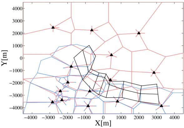
2.8.2 Partially Overlaying LTE and 3G Co-Sited Networks with Lim-ited LTE Coverage . . . 29
2.8.3 Fully Overlaying LTE and 3G Co-Sited Networks . . . 32
3 Inter-RAT Handover Parameters and Mobility Failure Types 35 3.1 Introduction . . . 35
3.2 Inter-RAT Handover Parameters . . . 36
3.2.1 Handover Thresholds . . . 36
3.2.2 Time-to-Trigger . . . 38
3.2.3 Filter Coefficient . . . 39
X Contents
3.3.1 Radio Propagation Conditions . . . 40
3.3.2 User Path . . . 43
3.3.3 User Velocity . . . 43
3.4 Inter-RAT Mobility Failure Types . . . 43
3.4.1 Radio Link Failures . . . 43
3.4.2 Costly Inter-RAT Handovers . . . 47
3.4.3 3GPP Specified Inter-RAT Mobility Failure Types . . . 47
3.5 Trade-offs in Inter-RAT MRO Problem . . . 48
4 Manual Optimization of Handover Thresholds 53 4.1 Introduction . . . 53
4.2 Network-Wide Optimization of Handover Thresholds . . . 55
4.3 Cell-Specific Optimization of Handover Thresholds . . . 58
4.3.1 Online Optimization using Drive Tests . . . 58
4.3.2 Offline Optimization using Simulated Annealing . . . 59
4.3.3 Offline Optimization using Taguchi’s Method . . . 61
4.3.3.1 Introduction . . . 61
4.3.3.2 Orthogonal Array . . . 61
4.3.3.3 Nearly Orthogonal Array . . . 64
4.3.3.4 Optimization Procedure Applying Nearly Orthogonal Array . . . 65
4.3.4 Performance Comparison between Simulated Annealing, Taguchi’s Method and Best Network-Wide Setting . . . 67
5 Automatic Optimization of Handover Thresholds 73 5.1 Introduction . . . 73
5.2 Performance Monitoring over Time . . . 74
5.3 Network-Wide Optimization of Handover Thresholds . . . 76
5.4 Cell-Specific Optimization of Handover Thresholds . . . 77
5.4.1 Formulation of the Optimization Problem . . . 77
5.4.2 Advantages and Limitations of Cell-Specific Optimization . . . . 80
5.4.2.1 Advantages over Initially Configured Network-Wide Setting . . . 80
5.4.2.2 Optimization Limitations . . . 81
5.5 Cell-Group Specific Optimization of Handover Thresholds . . . 82
5.5.1 Motivation . . . 82
5.5.2 Configuration of Handover Thresholds . . . 82
5.5.3 Formulation of the Optimization Problem . . . 83 5.5.4 Advantages and Limitations of Cell-Group Specific Optimization 85
Contents XI
5.5.4.1 Comparison between Cell-Group Specific Serving and
Target Cell Threshold Configuration . . . 85
5.5.4.2 Advantages over Cell-Specific Optimization . . . 88
5.5.4.3 Optimization Limitations . . . 92
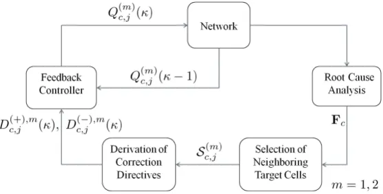
5.6 Optimization Loop of Handover Thresholds . . . 93
5.6.1 Introduction . . . 93
5.6.2 Root Cause Analysis . . . 93
5.6.3 Selection of Neighboring Target Cells for Handover Thresholds . 94 5.6.4 Derivation of Correction Directives for Handover Thresholds . . 94
5.6.5 Correction of the Values of Handover Thresholds using Feedback Controller . . . 96
5.6.5.1 Introduction . . . 96
5.6.5.2 Proportional Control Block . . . 98
5.6.5.3 Gain Scheduler . . . 100
5.7 Performance Evaluation and Analysis . . . 102
5.7.1 Cell-Specific Optimization of Handover Thresholds . . . 102
5.7.1.1 Network Level Performance Evaluation . . . 102
5.7.1.2 Cell Level Performance Evaluation . . . 105
5.7.1.3 Performance Comparison between Automatic Algo-rithm, Simulated Annealing and Taguchi’s Method . . 109
5.7.1.4 Optimization of Handover Thresholds Using Reduced Inter-RAT Mobility Failure Types as Specified by 3GPP Rel. 11 . . . 111
5.7.2 Cell-Pair Specific Optimization of Handover Thresholds . . . 113
5.7.2.1 Network Level Performance Evaluation . . . 113
5.7.2.2 Cell Level Performance Evaluation . . . 115
6 Joint Automatic Optimization of Handover Thresholds and Time-to-Trigger 119 6.1 Motivation . . . 119
6.2 Configuration of Handover Thresholds and Time-to-Trigger . . . 120
6.3 Classification of the Inter-RAT Mobility Failure Events into Two Sets of Key Performance Indicators . . . 121
6.4 Optimization Loop of Handover Thresholds and Time-to-Trigger . . . . 125
6.4.1 Introduction . . . 125
6.4.2 Detailed Root Cause Analysis . . . 126
6.4.3 Selection of Neighboring Target Cells for Handover Thresholds and Time-to-Trigger . . . 127
XII Contents
6.4.4 Derivation of Correction Directives for Handover Thresholds and
Time-to-Trigger . . . 127
6.4.5 Coordination Between the Update of Handover Thresholds and Time-to-Trigger . . . 130
6.4.6 Update of Handover Thresholds using Feedback Controller . . . 131
6.4.7 Update of Time-to-Trigger . . . 132
6.5 Performance Evaluation and Analysis . . . 132
6.5.1 Joint Optimization of Cell-Specific Handover Thresholds and Time-to-Trigger . . . 132
6.5.1.1 Network Level Performance Evaluation . . . 132
6.5.1.2 Cell Level Performance Evaluation . . . 133
6.5.2 Joint Optimization of Cell-Specific Serving Cell Threshold and Time-to-Trigger, and Cell-Pair Specific Target Cell Threshold . 136 6.5.2.1 Network Level Performance Evaluation . . . 136
6.5.2.2 Cell Level Performance Evaluation . . . 138
7 Cell Area-Based Automatic Optimization of Handover Thresholds 141 7.1 Motivation . . . 141
7.2 Configuration of Handover Thresholds . . . 142
7.3 Formulation of the Optimization Problem . . . 144
7.4 Location-Based Application of Handover Thresholds . . . 147
7.5 Advantages and Limitations of Cell-Area Based Optimization . . . 148
7.5.1 Advantages over Cell-Based Optimization . . . 148
7.5.2 Optimization Limitations . . . 150
7.6 Cell Area-Based Optimization Loop of Handover Thresholds . . . 151
7.6.1 Introduction . . . 151
7.6.2 Root Cause Analysis per Area . . . 152
7.6.3 Selection of Neighboring Target Cells for Handover Thresholds . 152 7.6.4 Derivation of Correction Directives for Handover Thresholds . . 152
7.6.5 Correction of the Values of Handover Thresholds using Feedback Controller . . . 153
7.7 Performance Evaluation and Analysis . . . 153
7.7.1 Network Level Performance Evaluation . . . 153
7.7.2 Cell Level Performance Evaluation . . . 156
8 Summary and Outlook 159 Appendix 163 A.1 Proof of (5.12) . . . 163
Contents XIII A.3 Proof of (7.14) . . . 167 List of Acronyms 169 List of Symbols 173 Bibliography 183 Lebenslauf 193
1
Chapter 1
Introduction
1.1
Self-Organizing Radio Networks
Nowadays, mobile communications becomes a staple commodity which is indispensable for daily life. The advances in mobile technologies have enabled the emergence of new classes of mobile devices such as smart phones and tablets. These mobile devices allow the users to access the internet and benefit from a wide range of online services. Moreover, the open architecture of some mobile operating systems has boosted the development of a significant number of mobile applications which have great impact on individuals as well as on businesses [Has12]. The high diversity in user applications and services has caused mobile communications to become an integral part of everyday life.
The explosive growth in wireless data usage [Ame11] has fostered mobile networks to evolve from circuit switched paradigm with hierarchical network architecture to a flexible packet switched radio access technique with flat architecture as realized in LTE. New 4th Generation (4G) systems such as LTE are being deployed by mobile operators on top of legacy 2nd Generation (2G) or 3rd Generation (3G) mobile system. The co-existence of multiple RATs offers mobile operators an efficient means to meet the different data rate requirements of the users [BAE+09]. For further improvements,
small cells such as femto and pico cells are foreseen to provide more coverage and offload some of the macro cells [AEaG13, ONY+11]. This heterogeneity in RATs and
types of cells makes the network more diverse and complicated.
The extension of the network to comprise new RATs and sites increases drastically the costs and the operational effort of mobile operators. The deployment of new mobile networks and sites increases Capital Expenses (CAPEX) comprising engineering and installation services [Cel08, MPJC10]. On the other hand, the parallel operation and maintenance of multiple networks increases significantly OPEX [ERX+13]. It is
esti-mated that about 24 % of a typical mobile operator revenue is spent on OPEX [She05]. At the same time, the multitude of tunable radio network parameters and intricate interactions among RATs impose new operational challenges [vdBLE+08]. Mobile
net-works are becoming more difficult to configure, optimize and maintain due to techno-logical complexities.
2 Chapter 1: Introduction
The increase in CAPEX and OPEX is accompanied, unfortunately, by a stagnation in the revenues of mobile operators [Has12, PZW11]. Despite the spectral efficiency gains of the new wireless technologies, the revenue measured on a per-Megabit (Mb) basis is dropping due to the rapid growth in data throughput [Ame11]. Moreover, the revenues are declining because of the high competition resulting in new flat-rate contracts for voice and data communications [Has12]. To remain competitive, mobile operators are seeking new techniques which cut their CAPEX and OPEX while maintaining a high quality network service.
The common objective of 3GPP standard [3GP07], mobile operator’s lobby Next Generation Mobile Networks (NGMN) [NGM06] and research projects such as FP7 SOCRATES [SOC08b] is to minimize the human involvement in network planning and optimization tasks. Currently, the configuration and optimization of the network is manually performed requiring the intervention of technical experts in network plan-ning, drive tests, optimization and maintenance tasks [ALS+08]. Moreover, the
net-work optimization processes are repetitive and need to be performed permanently in order to respond to the dynamic changes in network, environmental conditions and traffic [Ame11]. Considering the large-scale deployment of the mobile networks com-prising multiple RATs and thousands of sites, the network configuration and optimiza-tion costs are significant. As a means to reduce costs without degrading Quality of Service (QoS), manual operational tasks are replaced by automatic functionalities run-ning autonomously at the network side. Networks having such automatic configuration and optimization functionalities are called SONs.
The benefits of introducing self-organization to mobile wireless networks are in terms of CAPEX and OPEX reductions as well as performance enhancements [vdBLE+08].
The permanent and costly human involvement in network operation is minimized by using automatic functionalities which are always online in all nodes of the network. Minimization of the human intervention leads directly to a reduction in OPEX. In addition, the foreseen performance gains from self-organization exceed those obtained by traditional configuration and optimization methods [vdBLE+08]. The instantaneous
acquisition of information from the network enables self-organization applications to be less error-prone and to respond faster to the changes in the network. The performance gains in coverage, capacity and QoS help to reduce the number of sites or allow for a delayed investment in additional cells which directly shrinks CAPEX.
The functionalities of SON include configuration, optimization and self-healing [FS08]:
ba-1.2 Inter-RAT Mobility Robustness Optimization 3
sic setup of the Base Stations (BSs). Self-configuration is active in pre-operational phase when the BSs are powered up for the first time and prior to Radio Fre-quency (RF) transmission.
• Self-optimization procedures are used to auto-tune the radio network parameters. These procedures work in operational phase and respond online to the changes in the network. The optimizations rely on the measurements of UEs and BSs as well as on performance measurements.
• Self-healing procedures detect automatically operational failures in BSs and apply self-healing mechanisms to recover from these failures.
1.2
Inter-RAT Mobility Robustness Optimization
For each of the three SON functionalities described in Section 1.1, a set of use cases are defined in [NGM07, 3GP11]. For instance, the main use cases of self-optimization are neighbor cell list self-optimization [LH11], coverage and capacity opti-mization [NuIAJHMT10, NuIMT12a, NuIMT12b], mobility load balancing [LSJB10, AWVK10a, AWVK10b] and MRO [KKYK11, HL12]. The recommendations and re-quirements on each use case are given in [NGM08, SOC08a]. They mainly describe the technical and business requirements of each use case and its corresponding expected outcome. Mobile operators have identified MRO as one the key tasks that requires automation as it is performed in their day-to-day operations [Ame11]. For this reason, MRO use case is considered in this thesis and it is described in detail in the following. The general aim of MRO use case in SON is the automatic optimization of the param-eters affecting the handovers of UEs for the sake of ensuring a proper end-user mobility in the network [HSS12], i.e., when moving from a source cell to a target cell. Incor-rect handover parameter settings can negatively impact the user experience and waste network resources by causing mobility problems such as Handover Failures (HOFs), Radio Link Failures (RLFs) and Unnecessary Handovers (UHs). RLFs or HOFs can lead to a call drop if the connection of the UE is not re-established, and consequently have more impact on user perception than other mobility problems. Costly handovers such as Ping-Pongs (PPs), which are consecutive back and forth handovers during a short time, lead mainly to inefficient usage of network resources.
Different types of handovers exist depending on the RAT and operating carrier frequen-cies of source and target cells. The handover types are shown in Fig. 1.1. Intra-RAT
4 Chapter 1: Introduction
handover occurs between a source and target cell of the same RAT. On the other hand, inter-RAT handover occurs between a source and target cell of different RATs operating at two different carrier frequencies, e.g., LTE and 3G. Moreover, the
intra-Figure 1.1. Different types of handovers.
RAT handover is further differentiated between intra-frequency and inter-frequency. In the former case, the source and target cells of the same RAT operate at the same carrier frequency whereas in the latter case the two cells operate at different carrier frequencies.
The main difference between intra-frequency and inter-frequency handover, including inter-RAT case, is the interference experienced by the UE during the handover. In intra-frequency handover, the handed over UE suffers from the interference between source and target cells. This is schematically illustrated in Fig. 1.2(a) that shows the received signal strengths of a UE from both source and target cells as a function of its distance from the BS. If the UE is handed over to the target cell before it reaches the border of the source cell (dashed line), determined by the mobility handover parameter settings, the interference induced by the previously serving cell would be high, which in turn can cause an RLF due to a Too Early Handover (TEH). On the other hand, if the handover is executed after the UE has crossed the border of the serving cell, an RLF could occur due to a TLH. Thus, the success of intra-frequency handover highly depends on the time instant of handover execution.
In inter-frequency handover, a UE does not experience any interference from the source cell if it is handed over to the target cell. This is illustrated in Fig. 1.2(b) which shows an inter-frequency example of a UE attempting to hand over from a source cell in RAT A to a co-sited target cell in RAT B. In inter-frequency handover, there is no so-called “cell edge problem” as source and target cells operate at different frequencies. Moreover, there is a large area where the UE can connect either to the source or target cell with good signal level.
1.2 Inter-RAT Mobility Robustness Optimization 5
(a) Intra-frequency handover: The target cell is an interferer.
(b) Example of an inter-frequency handover: No interference between different operating fre-quencies.
Figure 1.2. Impact of interference during the handover of a UE in intra-frequency (left) and inter-frequency (right) scenarios.
This thesis focuses on MRO between two RATs. As an example, an LTE network overlaying with a 3G network is considered. Nevertheless, the presented concepts and optimization approaches could be, in principle, applied for all types of RATs, e.g., 2G or Worldwide Interoperability for Microwave Access (WiMAX).
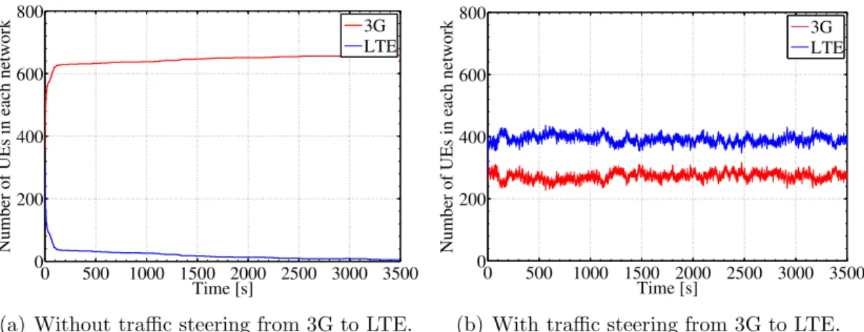
The co-existence of two overlaying LTE and 3G networks provides mobile operators a high degree of flexibility for matching network resources to application requirements. As LTE provides much higher peak throughput than 3G [HT09], high data rate users can be served by LTE and the rest by 3G network. Thus, a better utilization of radio resources can be achieved by handing over LTE capable users having high data rate requirements from 3G to the LTE network. This kind of inter-RAT handover is called traffic steering based handover as it yields a better distribution of load and traffic in both RATs [NPS11].
The handover of an UE to another RAT is also necessary when the coverage of the serving RAT becomes weak and a strong coverage from a different RAT exists. The radio coverage of a RAT can be insufficient in two cases: a) One RAT is deployed only for a limited geographical area while the other RAT is covering the full serving area, or b) Coverage holes exist in one RAT, mainly caused by physical obstructions such as buildings, tunnels or hills, and at the same time a good coverage exists from the other RAT. In order to provide a service continuity, a user reaching the end of coverage area or approaching a coverage hole should be handed over to another RAT if possible.
6 Chapter 1: Introduction
The inter-RAT handover of a UE relies on filtered signal measurements of the serving and target cells. The impact of fast fading on signal measurements is averaged out by applying first Layer 1 (L1) averaging, then Layer 3 (L3) filtering using a filter coefficient parameter [3GP12b, 3GP12g]. These filtered measurements are reported by the UE to the serving BS either periodically or event-triggered. In the latter case, the measurements are reported when the serving signal is below a first threshold and the target signal is higher than a second threshold for a certain TTT interval. Once the measurement report is received, the inter-RAT handover is prepared and executed by the BS. The parameters affecting the inter-RAT handovers are namely the two aforementioned thresholds, TTT and filter coefficient parameter. The objective of inter-RAT MRO is to optimize automatically all or some of the handover parameters of each cell in order to ensure seamless handovers of UEs between RATs.
1.3
State of the Art
This section provides an overview of the previous works related to SON and MRO use case. The first part briefly describes the evolution of the methods followed in network configuration and optimization that yielded later on the inclusion of SON in future networks [Has12]. The second part discusses the relevant literature on MRO use case. The development of new RATs and network architectures have made the configuration and optimization operations much more difficult and complex. With the introduction of Wideband Code Division Multiple Access (WCDMA) along with new data services, the optimization trade-offs and the number of configuration parameters have increased significantly compared to 2G system [Has12, SPRSG+11]. As a result, new approaches and tools were required to support the network planning configuration and optimization processes [ZYAW06]. Some of these tools have incorporated automated optimization functionalities which made the network design more time-efficient and reduced the net-work deployment and maintenance costs [ABH+04,BJAPO05,NDA06,SVY06]. Driven
by the pressure from mobile operators to further reduce costs, SON is envisioned and introduced by 3GPP in 4G systems such as LTE to configure and optimize the cellular network automatically. Mobile operators have identified SON as one of the key means to reduce costs and to simplify the network management [SPRSG+11]. The previous
investigations on MRO use case are described in the following.
The research topic of intra-RAT MRO in SON has been extensively discussed in liter-ature, especially for LTE networks [JBT+10, Wei10, BJS+11, JBS+11, VWL+11].
1.3 State of the Art 7
inter-RAT MRO was given at first a lower priority than intra-RAT MRO which was specified by 3GPP in Rel. 9 and Rel. 10. Inter-RAT MRO has been specified in Rel. 11 and has been fed with results from this thesis. There was almost no prior art for inter-RAT MRO with the exception of basic network planning optimization methods which provide recommendations or techniques on how to set the handover parame-ters of legacy technologies such as 2G and 3G. In the following, the most relevant techniques for setting the inter-RAT handover parameters of 2G and 3G systems are summarized.
The work in [SSJC05] proposes a design for an inter-RAT handover algorithm in Universal Mobile Telecommunication System (UMTS) and Global System for Mobile Communications (GSM) networks. The deployment scenario consists of an island of UMTS cells surrounded by an ubiquitous GSM network. The main idea of the opti-mization algorithm is to set a hysteresis value between the parameters affecting in-going and out-going inter-RAT handovers. The authors show that for well-designed hysteresis values, a good trade off can be achieved between call drop rates, intra- and inter-RAT handover rates.
In [BGM+06], field tests measurements are used to find proper settings for the
param-eters controlling the inter-RAT handover from a WCDMA to a GSM network. The RF measurements are logged during a drive test in a route which is leaving WCDMA coverage and they are passed to an emulator for processing. The impact of different parameter settings on inter-RAT handover performance has been investigated. Using the test results, the authors recommend a set of handover parameters that lead to significant reductions in call drop rates in WCDMA.
Cell-specific parameterization of inter-RAT handover parameters has been suggested in [FSL+07] for a UMTS network overlaying partly with a GSM network. That is, each
cell applies specific values of handover parameters. The UMTS cells are distinguished according to their neighbor cell relationships and coverage areas. The following three types of cells are defined: Inner cell, transit cell and border cell. The inner cell is fully surrounded by nearby neighbors and has restricted coverage. The handover parameters of this kind of cell are configured such that inter-RAT handovers are almost disabled. A transit cell is fully surrounded by a lower number of neighbors than that of inner cell and has a larger coverage. This kind of cell should be more prepared for executing inter-RAT handovers to react on weak radio conditions. Finally, a border cell refers to an outer cell of the UMTS network which is not fully surrounded by nearby neighboring cells. For this cell, the inter-RAT handover of a UE to the GSM network should be triggered in time before a call drop happens due to missing coverage.
8 Chapter 1: Introduction
1.4
Open Issues
The automatic optimization of inter-RAT handover parameters in SON is a relatively new topic which has not been addressed much in literature as mentioned in Section 1.3. For this reason, many issues related to inter-RAT MRO are still open. In this section, the most important open issues are summarized as follows.
1. How to model and design a multi-RAT cellular system for investigating inter-RAT MRO while keeping the computational complexity low?
2. Which inter-RAT mobility failure types are needed for appropriate root cause analysis?
3. What is the new offline optimization method that can take into account the interactions among the configuration parameters, and how can it be used in network planning phase to efficiently optimize the handover parameters?
4. How to make use of Physical Cell IDs (PCIs) of neighboring target cells of han-dover in order to overcome the limitations of the current cell-specific optimization approach of handover thresholds in SON?
5. How to design an efficient algorithm for automatically optimizing the inter-RAT handover thresholds of each cell?
6. How to make use of the additional TTT parameter which is defined in Section 1.2 to improve the performance of the automatic algorithm optimizing only the han-dover thresholds of cells?
7. How to make use of the locations of mobility failure events to achieve an inter-RAT MRO solution which is better than cell-based optimization approaches where the handover thresholds are configured per cell?
1.5
Contributions and Outline of the Thesis
In this section, the outline of the thesis is given and the main contributions which answer the open issues of Section 1.4 are summarized.
Chapter 2 presents the system model of the multi-RAT cellular system and two rele-vant deployment scenarios for investigating inter-RAT MRO. This chapter addresses
1.5 Contributions and Outline of the Thesis 9
the challenges of open Question 1. The handover measurements and downlink Signal-to-Interference and Noise Ratio (SINR) are modeled such that the computational com-plexity of the inter-RAT MRO is reduced. The impact of fast fading is considered in handover measurements by generating and filtering the samples offline due to the small time granularity of L1 filtering procedure. Moreover, the models of the handover procedure and detection of RLFs are simplified in comparison with those specified in the 3GPP standard. Two deployment scenarios are considered for LTE and 3G co-sited networks. The scenarios are designed such that the user distribution is stationary over time, which is necessary for the evaluation of any automatic inter-RAT MRO algorithm.
The handover parameters and mobility failure types used for inter-RAT scenario are described in Chapter 3. The inter-RAT handover parameters: handover thresholds, TTT and filter coefficient are explained along with the factors affecting their settings. This chapter answers open Question 2. In contrast to the intra-RAT case, two types of TLHs exist: The first one is a TLH which is due to the misconfiguration of the serving cell threshold and the second is a TLH which is due to the misconfiguration of the target cell threshold. A scheme is proposed to classify a TLH into one of these types. The proposal to differentiate between the two types of TLHs has been recently adopted by LTE Rel. 11 standard [3GP12c].
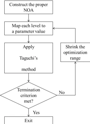
The manual optimization of inter-RAT handover thresholds, which requires human in-tervention, is presented in Chapter 4. The handover thresholds are initialized with a best network-wide setting, i.e., same handover thresholds for all cells of the network, and optimized later cell-specifically during network operation. Cell-specific optimiza-tion of handover thresholds can be performed as well using offline optimizaoptimiza-tion methods during the network planning phase. This chapter answers open Question 3. Taguchi’s method for experiment design is a promising offline optimization method that was developed at first for manufacturing processes. The method has been applied by the author of this thesis to optimize for the first time radio network parameters. The ad-vantage of Taguchi’s method compared to others, such as Simulated Annealing, is that it considers explicitly the interactions among the configuration parameters. Taguchi’s method is based originally on orthogonal array [Roy01] which is difficult to construct for arbitrary number of parameters while keeping the complexity of the method low. This limitation has been addressed by replacing the orthogonal array with a nearly orthog-onal array [AWVK11c] which can be constructed for arbitrary number of parameters and provides more flexibility in controlling the complexity of the method. Simula-tion results are shown to evaluate the performance of the newly introduced Taguchi’s method, Simulated Annealing and best network-wide setting of handover thresholds.
10 Chapter 1: Introduction
The automatic optimization of handover thresholds in SON is presented in Chapter 5. Currently, the handover thresholds are configured cell-specifically by the 3GPP stan-dard [3GP12b, 3GP12g]. The cell-specific optimization problem is formulated by the author of this thesis using the values of the Key Performance Indicators (KPIs) which are collected periodically in each cell. Moreover, the optimization limitations of cell-specific optimization problem are derived analytically. This chapter addresses open Question 4. Using the PCIs of neighboring target cells, the values of the KPIs can be differentiated with respect to neighboring target cells of handover. This allows for a cell-group specific optimization of the handover thresholds where a dedicated value can be configured with respect to a group of neighboring target cells. It is shown in this thesis that configuring only the target cell threshold in a cell-group specific manner is beneficial. This contribution of configuring the target cell threshold in a cell-group specific way has been submitted to LTE Rel. 11 standard [NN12]. Chapter 5 answers also open Question 5 of Section 1.4. The optimization loop of the handover thresh-olds, configured cell-specifically or cell-group specifically, is described in Section 5.6. To obtain steady improvements, a feedback controller is used to change the values of handover thresholds. The performance of the newly introduced cell-group specific op-timization approach is compared by means of simulations to that of the cell-specific optimization approach and the best network-wide setting of handover thresholds. The automatic algorithm of Chapter 5 optimizing only the handover thresholds is extended to include the TTT parameter. The joint optimization algorithm of the handover thresholds and TTT is presented in Chapter 6. This chapter answers open Question 6. The inter-RAT mobility failure events are classified into two sets of KPIs: The first set comprises the mobility failure events which can be resolved only by the handover thresholds and the second one comprises the mobility failure events which can be resolved by TTT. Based on the values of these two sets of KPIs, a decision is made on whether to change either the handover thresholds or TTT. The performance of the joint optimization algorithm of the handover thresholds and TTT is compared with that of the algorithm optimizing only the handover thresholds. The performance comparison is carried out for cell-specific and cell-group specific target cell thresholds. In Chapter 7, a cell-area based optimization algorithm of handover thresholds is pre-sented. This chapter provides the answer of open Question 7. Unlike cell-based opti-mization approaches of Chapter 5, the coverage area of each cell is decomposed into small tiles or areas and dedicated handover thresholds are assigned for each area. The cell-area based optimization problem is formulated in terms of the mobility failure events which are collected periodically for each area. The optimization of the han-dover thresholds of each area can be performed with respect to all neighboring cells or a group of neighboring cells. The former and latter new optimization approaches
1.5 Contributions and Outline of the Thesis 11
are denoted by cell-area specific and cell-area group specific optimization approaches, respectively, in analogy to cell-specific and cell-group specific optimization approaches of Chapter 5. The performance of the cell-area based optimization approach is com-pared with that of the best network-wide setting, cell-based optimization approaches of handover thresholds and joint optimization of handover thresholds and TTT. The thesis is concluded in Chapter 8 which summarizes the main results and provides an outlook on future work.
13
Chapter 2
System Model
2.1
Introduction
This chapter presents the system model and the scenarios that are used for inter-RAT MRO investigation.
Traditional models for system level simulators are not appropriate for SON mechanisms since they focus on scheduling and Radio Resource Management (RRM) which operate at a small time scale, generally in the order of Transmission Time Interval (TTI) in ms [VDL09]. The underlaying variations in the environment which are tracked by MRO are rather slow and do not require a fast adaptation [MYYZ12]. Changes in propa-gation conditions, traffic and mobility behavior, e.g., new streets, would be visible for mobile operators when only enough statistics of mobility failure events are obtained. Reliable statistics are typically collected from the network during time intervals of min-utes, or even hours depending on the traffic in the considered cell [VWL+11]. From
that perspective, the time scale of MRO is large unlike other highly adaptive function-alities such as RRM. In addition to this temporal aspect, MRO has another spatial aspect which is the simultaneous occurrence of mobility problems in different cells and the interdependencies among cells. A change of a handover parameter in a cell might trigger MRO in other neighboring intra- or inter-RAT cells, and if mobility problems are distributed in different areas of the network, many cells may apply MRO simulta-neously. These temporal and spatial aspects of MRO increase the complexity of the simulative investigation.
To consider time periods of several minutes or hours, low complexity models of the network are necessary for efficient simulative investigation. In this chapter, models for the measurements of the UE, handover procedure, RLF detection and average SINR in downlink are proposed. The models of the UE measurements consider effects varying on a small time scale such as fast fading without increasing the computational complexity. This is accomplished by generating the samples of fast fading offline and adding them to the measurements during the simulation. In addition, the author proposes two deployment scenarios of overlaying LTE and 3G networks for inter-RAT MRO investigation.
This chapter is organized as follows. The network layouts of LTE and 3G networks are described in Section 2.2. The radio signal propagation model comprising the effect
14 Chapter 2: System Model
of path loss, shadowing and antenna beam pattern is discussed in Section 2.3. The measurements of the UE which are used for handover decisions are described in Sec-tion 2.4 along with the filtering procedures applied for measurements. The model of the average SINR in downlink is presented in Section 2.5 for a UE served by an LTE or 3G cell. Section 2.6 explains the handover procedure model of UE. The detection model of RLF is provided in Section 2.7. The last Section 2.8 introduces the two de-ployment scenarios for simulative MRO investigation which consist of two partially or fully overlaying LTE and 3G co-sited networks.
2.2
Cellular Layouts of LTE and 3G Networks
This section describes the cellular layouts of LTE and 3G networks.
Each LTE and 3G BS has a tri-sector antenna. All transmit antennas of BSs are mounted at a height hbs. The index of the BS is b = 1, . . . , Nbs, where Nbs is the total
number of LTE and 3G BSs. The cell index is c = 1, . . . , Nc, where Nc is the total
number of LTE and 3G cells. The set of LTE and 3G cells is given by C ={1, . . . , Nc}.
Each cell cis served by a BS at position pc. Due to sectorization, some cells have the same BS position. The network to which each cellcbelongs is given byℓc =w∈ {1,2}, wherewequal to 1 and 2 indicates LTE and 3G network, respectively. The set of inter-RAT neighbors of cell c is given by Nc defined as
Nc ={i1, . . . , ik, . . . , iK|ik∈ C, ℓik 6=ℓc} (2.1)
wherek is the index of theK inter-RAT neighbors of cell c. The total number of UEs is denoted byNue. Each UEuis located at a positionvu on the ground, i.e., UE height is zero.
2.3
Radio Signal Propagation Model
In this section, the models of path loss, shadowing and 3-Dimensional (3-D) antenna beam pattern are described. Fast fading is not considered as it is discussed in Sec-tion 2.4 where measurements of UEs and filtering procedures are presented.
The path loss is the attenuation in signal strength of a transmitted signal and depends only on the distance between the transmitter and receiver [Gol05]. The distance be-tween a BS serving cellcand UEuis denoted bydc,u=|pc−vu|. The path loss model
2.3 Radio Signal Propagation Model 15
is given in dB scale by
Lp(dc,u) =αp+βp·10 log10(dc,u [km]) (2.2) where αp is a propagation constant and βp is the path loss exponent [3GP06].
Shadowing, also referred to as small scale fading, is modeled as a random process caused by obstacles in the environment which attenuate the power of the transmitted signal [Gol05]. For simulations, shadowing is considered by using a so-called shadowing map for each BS, which is a deterministic function of a particular position of a UEuin the network [VDL09]. The samples of the shadowing map are log-normally distributed with zero mean and standard deviation σsf given in dB [Rap02]. In addition, the
shadowing maps of cells served by the same BS are fully correlated.
The shadowing value corresponding to UEu located at positionvu with respect to BS
b is denoted by Mb(vu). According to [VVGZ94], Mb(vu) can be expressed as the sum of two independent componentsξw(vu) andηb(vu): The former refers to the near field component and is common for all BSs of the same network w, whereas the latter is BS-specific, and in turn independent for different BSs. Thus, Mb(vu) is formulated as
Mb(vu) = p ζbs·ξw(vu) + p 1−ζbs·ηb(vu) (2.3) with E[ξw(vu)] = E[ηb(vu)] = 0, (2.4) Var[ξw(vu)] = Var[ηb(vu)] =σsf2 for all b, (2.5)
E[ξw(vu)ηb(vu)] = 0 for all b, (2.6) and
E[ηb1(vu)ηb2(vu)] = 0 for all b1 6=b2, (2.7)
where E[.] and Var[.] denotes the mean and variance operator, respectively. The pa-rameter ζbs is the correlation coefficient pertaining to shadowing values of two BSs of
the same network and it is given by E[Mb1(vu)Mb2(vu)]
σ2 sf
=ζbs, and b1 where b2 are of same network. (2.8)
There is also spatial correlation between the shadowing values of a single shadowing map which is given by the de-correlation distance dcorr. Two shadowing valuesMb(v1)
and Mb(v2) have some correlation if they are separated by a distance smaller than dcorr [3GP06].
16 Chapter 2: System Model
The correlation coefficient pertaining to shadowing values of two fully co-sited BSs of different networks is denoted by 0 ≤ ζnw ≤ 1. The setting of ζnw is elaborated in
Section 2.8 which discusses the deployment scenarios of LTE and 3G networks.
Apart from path loss and shadowing, the signal strength received by a UE depends on the tilt and azimuth orientation of the transmit antenna. A 3-D antenna beam pattern is used and is approximated by summing up the azimuth and vertical patterns.
The azimuth pattern of the antenna serving cellcis determined by azimuth orientation Φc, azimuth beam width ∆φ and maximum azimuth attenuation Bh. The azimuth
patternBφ(Φc, φ) of the antenna serving cell c is given by [3GP10] as
Bφ(Φc, φ) =−min Bh,12· φ−Φc ∆φ !2 (2.9) where angleφ =∠(pc −vu).
Similarly, the tilt of the antenna serving cellcand the elevation beam width are denoted by Θc and ∆θ, respectively. The vertical pattern Bθ(Θc, θ) of the antenna is given by
Bθ(Θc, θ) =−min Bv,12· θ−Θc ∆θ !2 (2.10)
where Bv is the maximum elevation attenuation and angle θ = arctan(hbs/|pc−vu|).
The 3-D pattern of the antenna in sector cis expressed as a sum of the two aforemen-tioned patterns as given by
B(Φc, φ,Θc, θ) =−min{−(Bφ(Φc, φ) +Bθ(Θc, θ)), Ba} (2.11)
where Ba is the maximum backward attenuation [Hop03].
The overall signal attenuation Ac(dc,u,vu,Φc,Θc) at the UE u served by a cell cof BS
b is computed as
Ac(d,vu,Φc,Θc) =Lp(dc,u)−Ggain−B(Φc, φ,Θc, θ) +Lpn+Mb(vu) (2.12) where Ggain, expressed in dBi, is the antenna gain andLpn is the penetration loss.
2.4 UE Measurements and Filtering 17
2.4
UE Measurements and Filtering
2.4.1
Introduction
The handover decision relies basically on downlink signal measurements which are performed by the UE. The UE is configured to carry out measurements for the serv-ing cell and neighborserv-ing cells. Dependserv-ing on the measurement configuration, the UE measures the signals of neighboring cells of the same or different RATs. Two mea-surement quantities are used for handover decisions: Signal strength or signal quality measurements [3GP12e]. The latter quantity considers the received signal strength of the serving cell in relation to the interference of other neighboring cells of same RAT. The raw UE measurements are impacted by fast fading and other measurement errors. To eliminate these short-term variations and inaccuracies, two steps of filtering are applied to the measurements prior to any measurement reporting. First, L1 filtering is used to filter out the effect of fast fading and obtain stable estimates [3GP12d]. Then, L3 filtering is applied to smoothen the measurements received from L1 by filtering out measurement errors and residual signal fluctuations [3GP12g].
This section is organized as follows. The model of fast fading is given in Section 2.4.2. The measurements of the UE are given in Section 2.4.3. L1 filtering of fast fading is explained in Section 2.4.4. The model of measurement error is provided in Section 2.4.5 followed by a description of L3 filtering in Section 2.4.6.
2.4.2
Fast Fading Model
Fast fading refers to the rapid fluctuations in the signal amplitude resulting from mul-tipath propagation [Sin10]. If the number of scattering objects is large and there is no light-of-sight signal path between the transmitter and receiver, the amplitude of the signal can be modeled according to a Rayleigh distribution given by
fxff(xff) = xff σ2 ff ·e − x 2 ff 2σ2 ff (2.13)
wherexff is a realization of the Rayleigh distributed Random Variable (RV)xff [Mol03].
According to [SOZ11], an LTE capable UE should be equipped with at least two receive antennas. As this investigation studies inter-RAT MRO between LTE and 3G,
18 Chapter 2: System Model
all UEs are assumed to be LTE capable. Assuming that the multipath fast fading processes at each of the two receive antennas are statistically independent, a diversity order of two is achieved resulting in less critical fading power attenuation. This is shown in Fig. 2.1 which plots the power envelope, i.e., square of the amplitude, of the multipath fast fading in dB as a function of time in ms for a UE moving at a speed of 3 km/h: The red and blue curves correspond to the case when the UE is equipped with one receive antenna and two receive antennas, respectively. According to Fig. 2.1, the
0 500 1000 1500 2000 2500 3000 −50 −40 −30 −20 −10 0 10 Time [ms]
Power envelope of fast fading [dB]
1 Receive antenna 2 Receive antennas
Figure 2.1. The power envelope of the multipath fast fading in dB as a function of time in ms for a UE moving at a speed of 3 km/h: The red and blue curves correspond to the case when the UE is equipped with one receive antenna and two receive antennas, respectively.
power envelope of the multipath fast fading corresponding to a single receive antenna experiences higher number of severe dips compared to that of two receive antennas. In other words, fast fading is less critical in case the UE is equipped with two receive antennas.
In case of a single receive antenna, the power envelope of the multipath fast fading is computed by taking the power of realizations of xff, generated according to the
Jakes model [Jak74] for Rayleigh flat fading. In this case, the power envelope of the multipath fast fading is exponentially distributed [Sha11] and its corresponding probability distribution function (pdf) is shown in red in Fig. 2.2. In case of two receive antennas, the power envelope of the multipath fast fading is obtained by generating two independent realizations of xff and averaging their corresponding power values.
As a result, the power envelope of the multipath fast fading is chi-squared distributed with four degrees of freedom [Sha11] as shown in blue in Fig. 2.2. For both one and two receive antennas, the average of the power envelope of the multipath fast fading is zero in dB.
2.4 UE Measurements and Filtering 19 0 1 2 3 4 0 0.2 0.4 0.6 0.8 1
Power envelope of fast fading
1 Receive antenna 2 Receive antennas
Figure 2.2. The pdf of the power envelope of the multipath fast fading: The red and blue curves correspond to the case when the UE is equipped with one receive antenna and two receive antennas, respectively.
2.4.3
Modeling of UE Measurements
2.4.3.1 Introduction
The serving BS in an LTE or 3G network configures the UE to perform signal mea-surements for the serving and intra- or inter-RAT neighboring cells. For instance, the UE can be configured to start measuring the neighboring inter-RAT cells when the signal measurement of the serving cell falls below a certain network configured thresh-old. In this study, it is assumed that inter-RAT measurements are performed by the UE at each time step tn where n is the index for the time steps. The time elapsed between two simulation time steps is fixed and is indicated by the time step size Tn
which is expressed in ms. Moreover, in order to perform signal measurements for neigh-boring inter-RAT cells, a UE has to interrupt its serving connection for measurement gaps [KH08]. From that perspective, inter-RAT measurements are quite costly unlike intra-RAT measurements which do not require any measurement gaps. Different mea-surement quantities can be configured by each BS. The meamea-surement quantities are described first for LTE cells then for 3G cells.
2.4.3.2 Measurements of LTE Cells
The first measurement quantity is the Reference Signal Received Power (RSRP) which is a signal strength measurement, expressed in dBm. RSRP is defined as the linear
20 Chapter 2: System Model
average over the power contributions of the resource elements that carry cell-specific ref-erence signals within the considered measurement bandwidth [3GP12e]. The resource element is the smallest frequency and time unit which is used for downlink transmis-sion and corresponds to a single 15 kHz sub-carrier during one Orthogonal Frequency Division Multiplexing (OFDM) symbol interval [Tol11]. The transmit power of cell c
on a single resource element is given by Pc(tx,re) in dBm. Considering a total transmit power Pc(tx) and an LTE system bandwidthW,Pc(tx,re) is computed as
Pc(tx,re)=Pc(tx) −10·log10 W [MHz] 15·10−3 [MHz]
!
, (2.14)
where 15·10−3 is the sub-carrier bandwidth in MHz.
The RSRP of an LTE cell cmeasured by a UEuat time step tn is modeled in dB scale as
RSRPu,c(tn) = Pc(tx,re)−Ac(d,vu(tn),Φc,Θc) +αu,c(tn), (2.15) where Ac(d,vu(tn),Φc,Θc) defined in (2.12) is the overall signal attenuation of UE u at time step tn and αu,c(tn) in dB is the power envelope of the multipath fast fading on the link between cell c and UE u at time step tn. The power envelope αu,c(tn) is chi-squared distributed with four degrees of freedom. The linear form of RSRPu,c(tn) is denoted by RSRPu,c(tn)|(lin).
The second measurement quantity is the Reference Symbol Received Quality (RSRQ) which is a signal quality measurement, expressed in dB. RSRQ is defined in linear scale as the ratio between RSRP and Received Signal Strength Indicator (RSSI) [3GP12e]. RSSI comprises the linear average of the total received power observed only in OFDM symbols containing reference symbols [3GP12e]. Thus, RSSI includes the signal strength of the serving cell, interference from neighboring cells of the same RAT in addition to noise power. As the RSSI measurement comprises signal strength measure-ments of different cells, it is assumed that multipath fast fading is averaged out in the measurement process.
A Resource Block (RB) spans 12 contiguous sub-carriers and seven OFDM symbols in one slot with a duration of 0.5 ms [Sau10]. In a single RB, each of the two OFDM symbols out of seven contain two reference symbols. The transmit power of cell con a single RB is denoted by Pc(tx,rb) in dBm and is computed as
Pc(tx,rb) =Pc(tx)−10·log10
W [MHz] 12·15·10−3 [MHz]
!
2.4 UE Measurements and Filtering 21
Excluding the effect of fast fading, the received power on a single RB of a cellcmeasured by a UE u at time steptn is expressed in dB scale as
Pu,c(rx,rb)(tn) =Pc(tx,rb)−Ac(d,vu(tn),Φc,Θc). (2.17) The linear form of Pu,c(rx,rb)(tn) is given by Pu,c(rx,rb)(tn)
(lin).
The value of RSSI depends on the load of the serving and neighboring cells of the same RAT. The load of a cell cis denoted by 0≤ρc ≤1. In this study, a full buffer traffic model [VDL09] is assumed for users. That is, all RBs are used as soon as there is a single UE, and the load is ρc = 1. If the cell is empty, i.e., it does not serve any UE, the load is ρc = 0. Considering a single RB, the contribution of a fully loaded neighboring cell c in RSSI is the total received power Pu,c(rx,rb)
(lin). On the other hand,
the contribution of an empty cell in RSSI is the received power on two sub-carriers carrying reference symbols and is approximated by 2/12 of Pu,c(rx,rb)
(lin).
The RSRQ of an LTE cell c measured by a UE u at time step tn is modeled in linear scale as RSRQu,c(tn) (lin) = RSRPu,c(tn) (lin) RSSIu(tn) (lin) , where (2.18) RSSIu(tn) (lin) = X s∈C|ℓs=ℓc ρs·Pu,s(rx,rb)(tn) (lin)+ (1−ρs)· 2 12·P (rx,rb) u,s (tn) (lin) ! +PN(rb) (lin) (2.19) where PN(rb)
(lin) is the linear form of the noise powerP (rb)
N on a single RB in dBm.
2.4.3.3 Measurements of 3G Cells
The signal strength measurement of a 3G cell is the Received Signal Code Power (RSCP) which is measured over the full 3G system bandwidth W of (2.14). RSCP is expressed in dBm and is analogous to RSRP of an LTE cell. RSCP is defined as the received power on one code measured on the primary Common Pilot Channel (CPICH) [3GP12e]. The transmit power on CPICH channel, expressed by Pc(tx,cpich)in dBm, is equal in linear scale to 10 % of the total transmit power Pc(tx) on the full 3G system bandwidth. The RSCP of a 3G cell c measured by a UE u at time step tn is modeled in dB scale as
22 Chapter 2: System Model
The linear form of RSCPu,c(tn) is given byRSCPu,c(tn)
(lin).
The signal quality measurement of a 3G cell is calledEc/N0 and is analogous to RSRQ
of an LTE cell. Ec/N0 is expressed in dB and is defined in linear scale as the ratio
between RSCP and RSSI [3GP12e]. Similar to the RSRQ case, it is assumed that multipath fast fading is averaged out in the RSSI measurement. Excluding the effect of fast fading, the total received power of cell c by UE u at time step tn is expressed in dB scale as
Pu,c(rx)(tn) =Pc(tx)−Ac(d,vu(tn),Φc,Θc). (2.21) The linear form of Pu,c(rx)(tn) is denoted by Pu,c(rx)(tn)
(lin).
The contribution of a fully loaded neighboring cell c in RSSI is the total received power Pu,c(rx)
(lin). As for an empty cell, the contribution in RSSI is the received power
on control channels which is approximated by 20% of the total received power Pu,c(rx)
(lin).
TheEc/N0 of a 3G cellcmeasured by a UEuat time steptn is modeled in linear scale as [Ec/N0]u,c(tn) (lin)= RSCPu,c(tn) (lin) RSSIu(tn) (lin) , where (2.22) RSSIu(tn) (lin) = X s∈C|ℓs=ℓc ρs·Pu,s(rx)(tn) (lin)+ (1−ρs)·0.2·P (rx) u,s (tn) (lin) +PN (lin) (2.23) where PN
(lin) is the linear form of the total noise power PN in dBm.
2.4.4
Layer 1 Filtering
The L1 filtering is a procedure which is applied by the UE to average out fast fading. The procedure of L1 filtering is not specified by 3GPP. Typically, the L1 averag-ing length of intra-RAT and inter-RAT measurements is 200 ms and 480 ms, respec-tively [3GP12d].
The L1 filtering procedure of fast fading acts on a subframe basis in LTE and 3G. One subframe in LTE consists of two slots with a duration of 1 ms [HT09] whereas one subframe in 3G consists of three slots with a duration of 2 ms [HT07]. Thus, applying an online L1 filtering to RSRP and RSCP measurements would require a small simulation time step Tn of 1 ms. The use of such small time step would hinder the investigation