Virginia Commonwealth University Virginia Commonwealth University
VCU Scholars Compass
VCU Scholars Compass
Theses and Dissertations Graduate School
2017
Towards Design and Analysis For High-Performance and Reliable
Towards Design and Analysis For High-Performance and Reliable
SSDs
SSDs
Qianbin XiaFollow this and additional works at: https://scholarscompass.vcu.edu/etd
Part of the Computer and Systems Architecture Commons, and the Data Storage Systems Commons
© The Author
Downloaded from Downloaded from
https://scholarscompass.vcu.edu/etd/4904
This Dissertation is brought to you for free and open access by the Graduate School at VCU Scholars Compass. It has been accepted for inclusion in Theses and Dissertations by an authorized administrator of VCU Scholars
c
Qianbin Xia, May 2017
TOWARDS DESIGN AND ANALYSIS FOR HIGH-PERFORMANCE AND RELIABLE SSDS
A Dissertation submitted in partial fulfillment of the requirements for the degree of Doctor of Philosophy at Virginia Commonwealth University.
by QIANBIN XIA
B.S., Beijing Institute of Technology: Sep. 2007 to Jul. 2011
Director: Dr. Weijun Xiao,
Assistant Professor, Department of Electrical and Computer Engineering
Virginia Commonwewalth University Richmond, Virginia
Acknowledgements
I would like to express my sincere gratitude to my advisor Dr. Weijun Xiao, for his continuous support of my Ph.D study and research, for his patience and immense knowledge. His guidance helped me a lot in all the time of my research and writing of this dissertation. Without his guidance and persistent help, this dissertation would not have been possible. I would also like to thank my committee members, Dr. Wei Cheng, Dr. Preetam Ghosh, Dr. H. Klenke, and Dr. Ruixin Niu for serving on my advisory committee and for their insightful comments and encouragement. I would also like to extend my thanks to other faculty and stuff members of the department of Electrical and Computer Engineering, in particularly to the Dr. Xubin He, Dr. UMIT OZGUR, and administrative assistants Stacy E. Metz and Ellen Gresham.
Meanwhile, I thank my lab mates Dongwei Wang, Liang Xu and other close friends in ECE deparment: Ping Huang, Tao Lu, Yijie HuangFu, Yuhua Guo, and Kun Tang. They helped me a lot in both my study and life. There are also some local friends in Richmond like Bob and Elain, they have invited me several times to their beautiful farm and helped me a lot in my language skills.
I would like to thank my family in China: my parents, my sister, and my brother, for supporting me financially and spiritually. Especially my parents, I appreciate all the support they have provided me over the years. They taught me the value of hardwork and an education.
TABLE OF CONTENTS
Chapter Page
Acknowledgements . . . ii
Table of Contents . . . iii
List of Tables . . . v
List of Figures . . . v
Abstract . . . ix
1 Introduction . . . 1
1.1 Background and Problem Statement . . . 1
1.2 Proposed Approaches . . . 4
2 Flash-Aware High-Performance and Endurable Cache . . . 7
2.1 Introduction . . . 7
2.2 Related Work . . . 9
2.3 Design and Implementation . . . 11
2.3.1 Motivation Example . . . 11
2.3.2 LRU and ARC . . . 13
2.3.3 LRU-Based Flash-Aware Cache Design . . . 14
2.3.4 ARC-Based Flash-Aware Cache . . . 17
2.3.5 Discussions of Implementation Issues . . . 19
2.4 Experimental Methodology . . . 20
2.5 Experimental Results . . . 21
2.5.1 Cache Hit Ratio . . . 23
2.5.2 Impacts on Lifetime . . . 26
2.6 Summary . . . 28
3 Zero-Migration Garbage Collection Scheme for Flash Read Cache . . . . 29
3.1 Introduction . . . 29
3.2 Related Work . . . 30
3.3 Design and Implementation . . . 31
3.4.1 Impacts on Lifetime . . . 33
3.4.2 Performance . . . 35
3.5 Summary . . . 40
4 Locality-Driven Dynamic Flash Cache Allocation . . . 41
4.1 Introduction . . . 41
4.2 Background and Motivation . . . 44
4.2.1 Miss Ratio Curves . . . 44
4.3 Performance Modeling . . . 46
4.4 Design and Implementation . . . 48
4.5 Experimental Methodology and Results . . . 51
4.5.1 Performance . . . 55
4.5.2 Endurance . . . 56
4.5.3 Sensitive Analysis . . . 58
4.6 Related Work . . . 59
4.7 Summary . . . 61
5 Improving MLC Flash Performance with Workload-Aware Differenti-ated ECC . . . 62
5.1 Introduction . . . 62
5.2 Related Work . . . 64
5.3 Design and Implementation . . . 66
5.3.1 Analysis and Motivation . . . 66
5.3.2 Read and Write Separator . . . 69
5.3.3 Architecture and Working Flow . . . 70
5.3.4 Overhead Analysis . . . 72
5.4 Experimental Methodology and Results . . . 73
5.4.1 Experimental Methodology . . . 73 5.4.2 Experimental Results . . . 76 5.4.2.1 Parameters Exploration . . . 76 5.4.2.2 Performance . . . 78 5.4.2.3 Impacts on Lifetime . . . 83 5.5 Summary . . . 83
6 Conclusions and Future Work . . . 84
6.1 Conclusions . . . 84
6.2 Future Work . . . 86
LIST OF TABLES
Table Page
1 Parameters for SLC, MLC and TLC . . . 2
2 Configuration of Our Simulator . . . 21
3 Characteristics of I/O workload traces . . . 23
4 Difference of geometric Mean of Cache Hit Ratio with the integration of zero-migration GC scheme . . . 36
5 Configuration of Our Simulator . . . 52
6 Characteristics of I/O workloads traces . . . 52
7 Operation latency configuration . . . 73
LIST OF FIGURES
Figure Page
1 SSD Architecture [16].. . . 3
2 A simplified example to illustrate the motivation behind our
flash-aware cache design. . . 10
3 Comparison between normal ARC and flash-aware ARC. . . 17
4 Cache hit ratios of LRU, FLRU, ARC, and FARC. The cache
capac-ities used here include: 3GB, 4GB, 5GB, and 6GB. Over-provisions
configurations are 15%, 25%, and 35%. . . 22
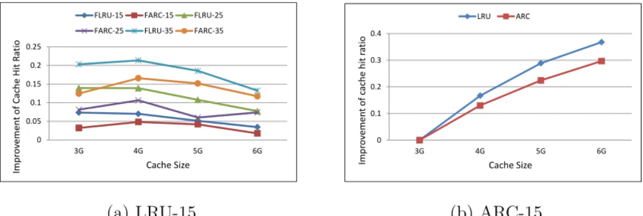
5 (a)Improvement of geometric means of cache hit ratios of FLRU and
FARC with different over-provisions, baselines are normal LRU and ARC algorithms, and (b)Improvement of geometric means of cache hit ratios with the increasing of cache size. The over-provision config-uration here is 15%. The cache hit ratios of 3G for LRU and ARC are used as our baselines for LRU and ARC respectively, all the results in
the figure are the differences with the baselines. . . 24
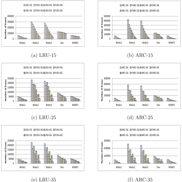
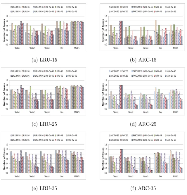
6 Erase count collected from simulation of LRU, FLRU, ARC, and
FAR-C. The cache capacities used here include: 3GB, 4GB, 5GB, and 6GB.
Over-provisions configurations are 15%, 25%, and 35%. . . 25
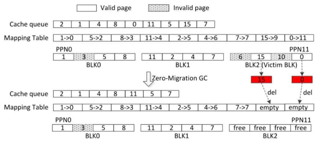
7 An example to illustrate the working flow of our zero-migration garbage
collection design.. . . 30
8 Normalized erase count collected from simulation of LRU, FLRU,
AR-C, and FARC with the integration of zero-migration GC scheme. The cache capacities used here include: 3GB, 4GB, 5GB, and 6GB.
9 Normalized geometric means of the average response time of FLRU, LRU-ZM, FLRU-ZM, FARC, ARC-ZM, and FARC-ZM with the nor-mal LRU and ARC as the baseline. The cache capacities used here includes: 3GB, 4GB, 5GB, and 6GB. Over-provisions configurations
are 15%, 25%, and 35%.. . . 37
10 Geometric means of the standard deviation of average reponse time
for LRU, FLRU, LRU-ZM, FLRU-ZM, ARC, FARC, ARC-ZM, and FARC-ZM. The cache capacities used here includes: 3GB, 4GB, 5GB,
and 6GB. Over-provisions configurations are 15%, 25%, and 35%.. . . 39
11 Miss ratio curve of Financial1. . . 45
12 System Architecture. . . 48
13 Average response time of different static over provision configurations
and our dynamic allocation scheme. . . 53
14 Cache hit ratios of different static over provision configurations and
our dynamic allocation scheme.. . . 54
15 Erase counts of different static over provision configurations and our
dynamic allocation scheme. . . 57
16 Effect of different time window sizes on the cache performance. . . 58
17 Spatial distribution of the read and write requests. . . 66
18 Read and write request distributions in the two-dimensional space
(log-ical address and timing space). . . 67
19 Read and write separator based on multiple bloom filters. . . 68
20 Architecture of our workload-aware differentiated ECC design. . . 71
21 Performance change with various values of m, here we fix the value of
n as 2. . . 75
22 Performance change with various values of n, here we fix the value of
23 Normalized overall performance comparison. . . 78
24 Normalized write and read performance comparison. . . 79
25 Distributions of different cost operations. . . 81
Abstract
TOWARDS DESIGN AND ANALYSIS FOR HIGH-PERFORMANCE AND RELIABLE SSDS
By Qianbin Xia
A Dissertation submitted in partial fulfillment of the requirements for the degree of Doctor of Philosophy at Virginia Commonwealth University.
Virginia Commonwealth University, 2017.
Director: Dr. Weijun Xiao,
Assistant Professor, Department of Electrical and Computer Engineering NAND Flash-based Solid State Disks have many attractive technical merits, such as low power consumption, light weight, shock resistance, sustainability of hotter operation regimes, and extraordinarily high performance for random read access, which makes SSDs immensely popular and be widely employed in different types of environments including portable devices, personal computers, large data centers, and distributed data systems.
However, current SSDs still suffer from several critical inherent limitations, such as the inability of in-place-update, asymmetric read and write performance, slow garbage collection processes, limited endurance, and degraded write performance with the adoption of MLC and TLC techniques. To alleviate these limitations, we propose optimizations from both specific outside applications layer and SSDs’ internal layer. Since SSDs are good compromise between the performance and price, so SSDs are widely deployed as second layer caches sitting between DRAMs and hard disks to boost the system performance. Due to the special properties of SSDs such as the
in-ternal garbage collection processes and limited lifetime, traditional cache devices like DRAM and SRAM based optimizations might not work consistently for SSD-based cache. Therefore, for the outside applications layer, our work focus on integrating the special properties of SSDs into the optimizations of SSD caches. First, we propose to leverage the out-of-place update property of SSDs to improve both the performance and lifetime of SSDs. Second, a new zero-migration garbage collection is proposed for SSD read cache to reduce the internal garbage collection activities and prolong the lifetime of SSDs without sacrificing the cache performance. Moreover, when SS-Ds are deployed as write caches, we come up with a locality-driven dynamic cache allocation scheme to improve both the performance and lifetime of SSD cache by compromising the cache hit ratio and the internal garbage collection overhead. Fi-nally, a workload-aware hybrid ECC design is proposed to alleviate the flash write performance degradation without hurting the read performance and data reliability.
CHAPTER 1
INTRODUCTION
1.1 Background and Problem Statement
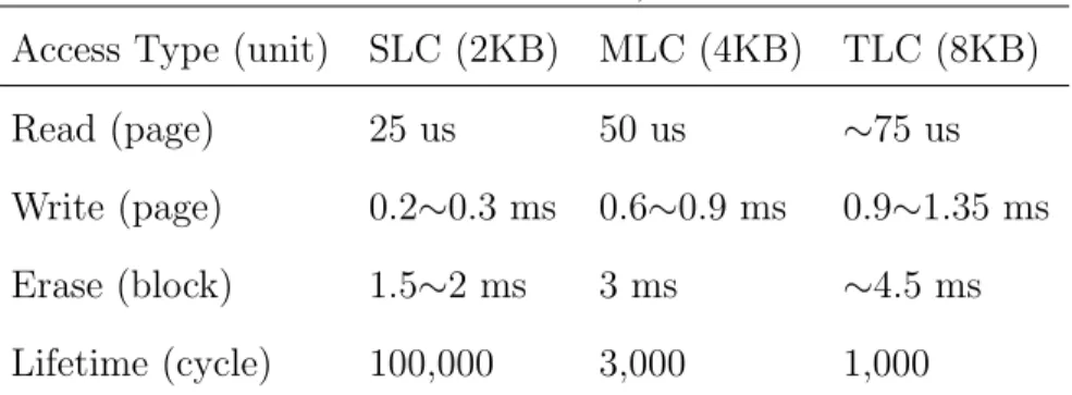
Flash memory is organized in units of blocks and pages. A fixed number (32 or 64) of pages compose a block. There are three main operations in flash memory: read, write, and erase. Read and write operations are performed in the unit of pages, while erase operations are on a block basis. Flash memory has several distinctive features, such as out-of-place updates, internal garbage collection, asymmetrical read and write performance, limited erase cycles, and plenty of internal parallelism. Before updating a flash page in SSDs in-place, the whole flash block need to be erased, which is a time-consuming process and introduce unacceptable write latency. Out-of-place update is adopted to mitigate the limitation of time-consuming in-place update. Instead of updating the data in-place, the new data is directed to other free blocks and the old version of data is marked as invalid. An internal garbage collection process will be trigged to reclaim these invalid flash pages due to the out-of-place updates. Before erasing the victim block, the valid data will be migrated to other free space and then the whole victim block will be erased. This internal garbage collection process could significantly affect the performance of SSDs. Besides, each flash block could only be erased limited cycles, after which, the flash block will be unreliable and marked as bad. What’s more, flash write operations are much slower than flash read, which could be the performance bottleneck of the SSDs. The emergence of MLC (stores two bit information per cell) and TLC (stores three bit information per cell) technology is to increase the memory density and reduce the price, while at the same time, impairs
the performance and endurance. Table 1 depicts the main parameters for SLC, MLC, and TLC flash memories [1].
Table 1. Parameters for SLC, MLC and TLC
Access Type (unit) SLC (2KB) MLC (4KB) TLC (8KB)
Read (page) 25 us 50 us ∼75 us
Write (page) 0.2∼0.3 ms 0.6∼0.9 ms 0.9∼1.35 ms
Erase (block) 1.5∼2 ms 3 ms ∼4.5 ms
Lifetime (cycle) 100,000 3,000 1,000
Since traditional file systems are designed for the in-place update storage de-vices, Flash Translation Layer (FTL) has been developed and deployed in SSDs to mimic in-place update like block devices in order to make flash memory compatible with the existing file systems. An FTL includes three main function units: address translation, garbage collector, and wear-leveler. The address translation unit trans-lates the logical page number to the physical page number in the flash memory and hides the erase-before-write feature of flash memory. The mapping methods could be coarsely classified into three categories: page-level mapping, block-level mapping, and hybrid mapping. A page-level mapping [2] can achieve the best performance, it is constrained by the limited resource of expensive SRAM. While a block-level mapping [3] could save huge amount of memory space for the mapping information, it will lead to space wastage and performance degradation. To reach a compromise, several hybrid schemes [4, 5, 6, 7, 8] have been proposed that combine the page-level and block-level mapping together and are mainly based on the following idea: most of the data are mapped at the block level to reduce the overhead, while a small fraction of the data that are frequently accessed are mapped at the page level to guarantee the performance. A garbage collector is used to reclaim the obsolete pages caused by the
out-of-place updates. Whenever the number of free pages drops below a predefined threshold, a garbage collection process will be triggered to create more free space for the incoming requests. A victim block will be selected from the pool, all the valid data in the victim block will be moved to other free space, then the whole block will be erased. There are several different algorithms to select the victim blocks: FIFO GC algorithm [9, 10, 11], which selects the blocks in a cyclic manner; greedy GC algorithm [11, 12], which selects the block with the fewest number of valid pages; the windowed GC algorithm [13], which is a combination of the FIFO and greedy algo-rithms; the d-choices GC algorithm [14, 15] which selects the victim block containing the fewest number of valid pages from d randomly chosen blocks. The objective of wear-leveler is to get an even erase-count distribution among all flash-memory blocks to improve the overall endurance of flash memory.
Host Interface Logic (SATA, PCI-E, etc.) Flash Controller and Memory Buffers Flash Demux/ Mux Host Interconnect RAM
Flash Translation Layer (Log-structured with
cleaning & wear-leveling) Gangs of flash packages with multiple planes Multiple Parallel Elements Figure 1:SSD Architecture.
the absence of higher-level semantics. Several previous works note this deficiency and propose more expressive interfaces [5–7, 9]; some even allow programming the storage controller [1, 16, 21]. One approach is to use an object-based interface [10, 11, 22], which exports the ab-straction of an object as a collection of bytes. Structures such as trees, tables, files, and directories can be repre-sented as objects, reflecting the higher-level semantics better than a block-based interface; the device controller performs block allocation and layout for the objects.
Solid-State Devices. An SSD consists of a set of flash memory packages that are connected to a controller (Fig-ure 1). Each package has one or more dies; each die has multiple planes, which in turn have many blocks; each block consists of many 4 KB pages [18].
SSDs differ from HDDs on 3 main properties. The first obvious difference is the absence of mechanical moving parts. Second, flash pages are non-overwrite in nature and must be erased before being overwritten. To hide the high erase overhead and create the abstrac-tion of an in-place write, modern SSDs implement a log-structured design [17] in the flash translation layer (FTL) [15]. To uniformly spread the block usage, wear-leveling is also implemented. Finally, SSDs have several layers of parallelism that is dictated by the flash packages and the way they are connected to the controller.
There are two types of NAND flash memory: single-level cell (SLC) and multi-single-level cell (MLC). SLC flash stores a single bit of data per cell, while MLC flash stores multiple bits per cell. MLC flash has some drawbacks such as shorter lifetime (10K erase cycles vs 100K erase cycles of SLC), slower write, and erase operations.
3 Failed Assumptions
In this section, we discuss the system-level assumptions that fail when applied to SSDs, and the reasons behind these failures. In Table 1, we list the original (1-3) and extended terms of the unwritten contract and state
focus only on block-management issues; more assump-tions may be added as our experience with SSDs grows. For comparison, we list RAID arrays and MEMS-based storage, but for the rest of the paper we focus only on how the assumptions fail on SSDs.
3.1 Sequential vs. Random
In a disk, the latency and bandwidth of sequential ac-cess are several tens of times better than random acac-cess. However, on SSDs that use a log-structured FTL [15], both sequential and random writes are likely to take sim-ilar time. Table 2 lists the ratio of sequential-to-random bandwidth for an HDD (a Seagate Barracuda 7200.11 drive) and several SSDs. One of the SSDs is simu-lated (S4slc sim) using the simulator from our previous work [2], while others are real (S1slc, S2slc, S3slc,
S5mlc). We anonymize the real SSDs because they
are engineering samples and pre-production models. To help the reader understand the results better, we specify whether the devices use SLC or MLC flash memory.
From the table, we can observe that SSDs (using SLC or MLC memories) have random-read performance that is only a few times smaller than their sequential-read per-formance. This is even true for writes on certain SSDs
(S1slc,S4slc sim,S5mlc), but not on all of them; in fact,
some of the SSDs (S2slc,S3slc) have random-write
per-formance that is worse than HDDs. One of the reasons for this poor performance is write amplification, which we will discuss later (§3.4).
From the above results, we can see that the gap be-tween sequential and random accesses is narrowing on SSDs. File systems that run primarily on SSDs must re-consider the need for complex policies to achieve block-level sequentiality. Instead, a file system must focus on higher-level operations such as object management, consistency, and recovery, and move the low-level block management to the SSD, using say, the OSD interface.
3.2 Logical-to-Physical Mapping
The second term of the unwritten contract considers the relation between logical and physical sectors, and un-derstanding it is important for I/O scheduling. On an HDD, nearby LBNs translate well to physical proximity. However, this contract fails on an SSD because of the log-structured design, cleaning, and wear-leveling, all of which make it harder to estimate the location of a log-ical sector. In fact, the physlog-ical location is irrelevant if the ratio of sequential to random accesses approaches 1. This further motivates the conclusion that the file system accesses must be in terms of objects (or parts of objects) Fig. 1. SSD Architecture [16].
Figure 1 shows the architecture of typical SSDs. A typical SSD is composed of a host interface, an SSD controller, DRAM, a flash controller, ECC engine, and flash chips. The SSD controller contains a processor and an SRAM to store the firmware. The controller is responsible for the data placement, garbage collection, wear leveling, and bad block management. DRAM is used to store both the user data and mapping information. The DRAM allocation between the data cache and mapping table could
is one of the key factors to the performance and lifetime of SSDs. The performance of each individual Flash chip is relatively poor. In order to provide higher bandwidth, modern SSDs are organized into multi-channels. All the channels are independent of each other and can work in a parallel way. Each channel has a flash controller to buffer the pending requests and send the requests to the lower level in a channel. Within a channel, there could be multi-packages and each package contains multiple dies. All these packages and dies could work in an interleaving manner. How to fully utilize the internal parallelism to boost the performance of SSDs is still an opening question. Finally, the ECC engine is deployed to encode and decode the user data and provide stronger reliability.
In summary, SSDs have several inherent properties including out-of-place up-date, internal garbage collection, asymmetrical read and write performance, limited lifetime, and internal parallelism, which motivates us to design new architectures and algorithms to fully exploit the merits and alleviate the limitations of SSDs for both SSD-based caches and primary storages.
1.2 Proposed Approaches
Our optimizations target both the outside application layers and internal com-ponents. For the outside application layers, we focus on the the cache where SSDs are deployed as caches. Previous work have shown the severe interferences between read and write [17, 18], when read and write requests are mixed together and sent to the same SSD. The interference could especially degrade the read performance of SSD cache due to much higher write and erase latencies. Moreover, mixed read and write data in the same Flash block can lead to higher garbage collection overhead. Besides, Xia et al. has shown that read and write requests could be well separated by analyzing the real word IO trace files. Therefore, in our work, we assume separate
SSD-based read and write caches are deployed in the system.
First, we propose to utilize the out-of-place update property of SSDs to improve the performance and lifetime of SSD read cache. Due to the out-of-place update, when a cache eviction occurs, only the metadata will be removed, however the real user data still resides in the flash memory and is accessible before the whole flash block being erased. Therefore, we propose a flash-aware cache design that leverage these evicted but still accessible data to improve both the performance and lifetime of SSD read cache.
Second, a new zero-migration garbage collection scheme is proposed to further extend the lifetime of Flash-based read cache. The valid data migration process inside SSDs during the garbage collection processes will not only introduce extra latency, but also bring additional write operations and hurts the lifetime of SSDs. However, when SSDs are used as read caches, all the data inside SSD cache always have exact copies in the hard disks or write buffers. Therefore, unlike traditional garbage collection processes, our zero-migration garbage collection scheme will aggressively erase the whole flash block without performing valid data migrations to reduce the latency and alleviate the lifetime issue.
Third, we come up with a new locality-driven dynamic Flash cache allocation design to improve both the performance and lifetime of Flash-based cache. SSDs have internal garbage collection activities, which can have significant impact on the cache performance. Moreover, SSDs have limited endurance. Therefore, traditional cache hit ratio oriented optimizations might not obtain consistent performance benefit and may even hurt the endurance of Flash-based cache. Our locality-driven dynamic Flash cache allocation design aims to achieve the optimal cache performance by com-promising the cache hit ratio and internal garbage collection overhead. What’s more, compared with traditional Flash cache configurations, our proposed design can also
help to prolong the device lifetime.
Finally, we propose a workload-aware differentiated ECC design to improve the Flash write performance. Due to the adoption of ISPP Flash programming scheme, there is an inherent tradeoff between the flash write performance and reliability. Our workload-aware differentiated ECC design applies a fast write scheme with stronger ECC scheme to enhance the flash write speed without compromising the read perfor-mance.
CHAPTER 2
FLASH-AWARE HIGH-PERFORMANCE AND ENDURABLE CACHE
2.1 Introduction
An SSD is a good compromise among performance, capacity, and cost. DRAM is too costly and obviously not a persistent storage medium (it loses data when power outage occurs). Conventional HDDs are too slow. Therefore, SSDs are widely used as caches sitting between DRAM and hard disk drives (HDDs) to fill the huge performance gap between DRAM and HDDs [19, 20, 21, 22, 23, 24, 25, 26]. Despite all these attractive merits, SSDs suffer from several inherent limitations, especially the limited erase cycles. Each flash block could only be erased limited cycles, after which the block will be unreliable and marked as bad block. In [20], the authors showed how serious the limited lifetime issue of SSDs could be. When a 60GB Intel 520 SSD is used as a data cache for a deduplication system, where the available capacity of SSD cache is 5% of the deduplicated data. By taking the write speed and the total allowed written amounts before wearing out of Intel 520 SSD into account, the expected SSD lifetime is only several days.
Flash-based SSDs have several distinct properties compared with hard disk drives. Two of the most important aspects are erase-before-write and out-of-place update. A page could only be updated after erasing a whole block which contains multiple pages. The erase operation takes about several milliseconds [27] which will degrade the write performance of SSDs, and out-of-place update is adopted to alleviate the influence of slow erase operations. Instead of updating the data in the original physical
loca-tion, the new data is written to a new free location and the previous data is marked as invalid which will be reclaimed in the future. To support out-of-place updates, a mapping table that associates logical page number with physical page number is maintained by the controller. Whenever the accumulation of invalid pages reaches a threshold, a garbage collection process will be triggered to reclaim the obsolete space. In a typical SSD, the real physical capacity is always larger than the user-addressable physical space, and the surplus space is called over-provision. The over-provisioning part of SSDs is used for two purposes. One is to support the out-of-place update and reduce the frequency of garbage collection. The other is to substitute bad blocks. For enterprise applications where reliability and performance stability are of paramount importance, a large amount of flash memory will be reserved as the over-provisioning space.
When SSDs are used as primary storage devices, previous research work has leveraged the out-of-place update property to improve the performance and alleviate the limitations of flash memory under some special application scenarios like RAID (Redundant Arrays of Inexpensive Disks) [28], CDP (Continuous Data Protection) [29], and Snapshots [30]. While, to the best of our knowledge, when SSDs are used as caches, none of the existing research work has utilized the out-of-place update property to improve the performance. For general cache algorithms, when there is a cache miss and the cache is full, a cache entry will be replaced out by a replacement algorithm, then the missed data will be loaded from the low level storage and inserted into the cache. However, for flash cache, the eviction merely removes the metadata, and the actual user data is still accessible and resides in the physical flash page before being updated or erased.
In this chapter, we propose a flash-aware read cache design through leveraging these evicted but still accessible pages inside SSDs with negligible overhead.
Addi-tionally, a new zero-migration garbage collection scheme is proposed and implemented to further mitigate the lifetime limitation of flash cache.
2.2 Related Work
When flash memory is used as cache, lifetime is one of the main concerns and is becoming more serious due to the continuous decreasing of feature size and adoption of MLC and TLC technologies. A number of solutions have been proposed to alleviate the lifetime problem, typical techniques focus on designing more robust ECC [31, 32], or on improving traditional wear-leveling techniques [33]. Due to the garbage collection and wear leveling processes, the actual number of write operations inside the flash memory is larger than the write requests from the host, which is called write amplification. Several research works tried to extend the lifetime of flash memory
through reducing write amplification [34, 35, 36]. CAFTL proposed by Chen et
al. [37] integrated the data-deduplication technique into the FTL of SSD to reduce unnecessary duplicate writes and save the lifetime of SSD.
Another way to improve the lifetime of flash memory is retention relaxation. Retention errors are the dominant source of flash memory errors which are caused by charge leakage after the flash cells being programmed [38]. Liu et al. [31] improved the write speed and mitigated the requirement for stronger ECC codes by relaxing the retention time requirement. Cai et al. [39] proposed FCR (Flash Correct-and-Refresh)
to extend the limited erase cycles due to retention errors. FCR reads, corrects,
and reprograms (in-place) or remaps the stored data before the accumulation of the retention errors exceeding the capability of ECC. Huang et al. [40] aggressively placed the frequently updated data into the worn-out flash blocks which could only sustain shorter retention time to prolong the lifetime of these dead blocks.
research work focuses on specific optimizations for the flash cache. BPLRU proposed by Kim et al. [41] deployed a RAM inside SSD as a write buffer to improve perfor-mance and lifetime of flash memory. Kgil et al. [19] put forward a scheme which split the flash cache into separate read and write regions with changeable error correction strength and cell density to improve reliability and lifetime of flash memory. NetApp used flash memory as a second level read cache while used the NVRAM as the second level write cache [42]. Soundararajan et al. [21] used a hard disk drive as a write cache for SSDs. How the partition between the user space and over-provisioning s-pace affects the performance of flash caches was explored in [43]. In that work, the over-provisioning space was dynamically configured based on the properties of the workloads to improve the performance and lifetime at the same time. All of the above proposed schemes are complementary to our solution.
1→23 0→15 3 2→12 2 7 4 0 5 10 11 1 9 10 11 8 5 6 7 4 LPN PPN Page-mapping Table 3 10 11 2 8 5 0 4 9 1 6 7 23 12 15 PBN:0 PBN:1 PBN:2 PBN:3 0 1 2 3 4 5 6 7 8 9 10 11 12 13 14 15 Request sequence: (15,R),(23,R),(12,R),(0,R),(1,R) 9 8→14 3→12 6→13
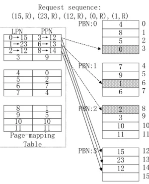
Fig. 2. A simplified example to illustrate the motivation behind our flash-aware cache design.
2.3 Design and Implementation
2.3.1 Motivation Example
In a page-level mapping scheme, a mapping entry consists of an LPN (logical page number) and a corresponding PPN (physical page number). The whole mapping table is constructed and maintained in both RAM and NAND flash memory. When a write request comes , the mapping table will be checked to verify whether the request is a new write or an update for existing data. For a new write, the data will be written to a free location and a new mapping entry will be added to the mapping table. While for an overwrite, first, the data will be written to a new free location, then the old page will be marked as invalid and the mapping table will be updated to reflect this change. But for a flash read cache, the situation is a little bit different. Invalid data will be generated only when a cache miss happens and the cache is full.
Figure 2 shows a simplified example of out-of-place update and the generation of invalid pages under a page-level mapping scheme. For simplicity, we assume that there are four physical blocks and each block consists of four pages. As we have mentioned, the flash memory has some over-provisioning capacity to support the out-of-place update and bad block replacement. In our example, although the real physical capacity is four blocks, user-addressable space is only 3 blocks. Equation (4.1) is the definition of over provision.
OP = (Ctotal−Cuser)/Ctotal; (2.1)
Ctotal is the real physical capacity, Cuser is the user-addressable capacity, OP means
the percentage of over-provision. We assume the OP is 25% in our example. Initially, the user-addressable space is full, but the over-provisioning part is totally empty. We use the corresponding logical page number to represent the user data in each physical
page. Then a series of requests come from the up level. A request is expressed by its LPN and operation type (read or write). In this figure, the dotted arrows point to the obsolete mapping information. The first request is a read request for LPN 15 which will result in a cache miss. Thus an entry will be evicted out based on a specific cache replacement algorithm for example LRU. Here we assume the LRU entry is LPN 0, so that entry will be evicted out and the corresponding data (PPN 3) will be marked as invalid. Then data for LPN 15 will be fetched from the lower storage device and written to PPN 12. The mapping entry for LPN 15 will be added to the mapping table. The next read requests for LPN 23 and LPN 12 are similar to the previous read request for LPN 23. The LRU cache entries will be evicted out and replaced by the new entries.
Then the fourth and fifth requests are both read requests for the previous evicted data. When treated as a traditional cache device like DRAM, these two requests will lead to two cache misses, we need to evict out two cache entries, fetch the data for LPN 0 and LPN 1 from the lower storage device, write the new data into the flash memory and then update the mapping information. This process will not only degrade the performance, but also reduce the lifetime of flash cache. Fetching data from the lower level storage device like HDDs will introduce a long latency, rewriting the new data into flash memory also brings timing overhead and more erase operations which is also a long-latency process and harmful to the lifetime of flash memory. Even the mapping entries for LPN 0 and LPN 1 have been evicted out from the mapping table, but the user data still reside in the PPN 3 and PPN 6. This gives us the opportunity to design a flash-aware cache architecture. Instead of fetching the data from the lower-level storage device and rewriting it into flash memory, we can merely revive it.
2.3.2 LRU and ARC
Least recently used (LRU) data replacement is one of the most basic and classic cache replacement algorithms. The main idea of LRU is: data recently used is likely to be reused in the near future; data not used in ages is not likely to be used again in the near future. To age the data, a queue will be maintained, recently used at the front and the oldest at the rear. Every time a page is referenced, it is moved to the head of the queue. When a cache miss happens and the cache is full, the LRU based policy evicts the entry which was requested least recently. Then for a read request, the missed data will be fetched from the lower storage device and written into the head of LRU queue.
Basic LRU merely captures the recency of workloads, Adaptive Replacement Cache (ARC) [44] improves the basic LRU algorithm by capturing both the recency and frequency at the same time and dynamically, adaptively, and continually bal-ancing between the recency and frequency components in an online and self-tuning fashion according to evolving and changing access patterns. In the original ARC ar-chitecture, the cache directory is split into two lists, T1 and T2. T1 is used to cache the recently referenced entries, while T2 is used to cache the frequently referenced entries. For any entries in T1, it should be accessed only one time recently, and for any entries in T2, it should be accessed at least twice. Two ghost lists B1 and B2 which only contain the metadata are attached to the bottom of T1 and T2. B1 and B2 are used to record the recently evicted entries from T1 and T2, respectively. The main idea of the learning process is as follows: if there is a hit in B1 then we should increase the size of T1, and if there is a hit in B2 then we should increase the size of T2. To support this learning process, a tunable parameter p is defined as the target size of T1. On a hit in B1, the value of p will be increased, and on a hit in B2, the
value of p will be decreased.
2.3.3 LRU-Based Flash-Aware Cache Design
Algorithm 1Flash-Aware LRU
Input: The read request streamx1, x2, ..., xt....
1: For everyt≥1 and anyxt, one of the following three cases must occur.
2: CaseI:xthits in the LRU queue.
3: Movextto the head of LRU queue.
4: Return the data.
5: CaseII:xtmisses in the LRU queue but hit in the SQ.
6: Move the tail entry from the LRU queue to the head of SQ.
7: Movextfrom SQ to the head of the LRU queue.
8: Return the data.
9: CaseIII:xtmisses in both the LRU queue and the SQ.
10: ifthe cache is full
11: Move the tail entry from the LRU queue to the head of SQ.
12: endif
13: Fetch the data from the lower level storage device into the SSD.
14: Movextto the head of LRU queue.
15: Return the data.
16: ERASE:
17: If the victim block contains any entries in SQ
18: Delete the corresponding entries in SQ.
19: endif
As we described previously, a cache eviction for a flash memory only discards the metadata, while the user data still resides in the physical location. When a read request for the evicted but still available data arrives, instead of fetching the data from the lower level storage device, we can revive the suspected data. Algorithm 1 shows our LRU-based flash-aware cache algorithm FLRU. We add a suspected queue (SQ) to preserve the evicted entries. The size of the LRU queue is determined by the user-addressable physical capacity. The maximal size of the SQ in the number of entries is given by equation (4.2).
NSQ = (OP −GCth)∗Ctotal; (2.2)
GCth is the garbage collection threshold which is defined as the percentage of free
physical capacity over the total physical capacity. The reason is that whenever the number of free pages drops to the garbage collection threshold, a garbage collection
process will be triggered to reclaim invalid pages. Therefore, only the subtraction between the over-provision and garbage collection threshold could be utilized by our flash-aware design. On a hit in LRU queue, we will move the requested entry to the head of the LRU queue and return the data like the normal LRU-based cache. On a miss in LRU queue, unlike original LRU-based cache, we will first check with the SQ. If the request hits in the SQ, we can revive it through moving the requested entry from the SQ to the head of the LRU queue. As the entries are maintained in the memory, hence the overhead of moving an entry from the SQ to LRU queue is negligible especially when compared with the long-latency lower-level read and flash write operations. Therefore the access latency of hitting in the SQ is almost the same as hitting in the LRU queue. In this case, a read operation in the lower-level storage device and a write request for the flash cache could be avoided. For a request which misses in both the LRU queue and SQ, we firstly need to move the tail entry from the LRU queue to the head of SQ if the LRU queue is full. Then the requested data will be fetched from the lower-level storage device and written into the flash memory. Besides adding the additional SQ and changing the original LRU algorithm, we also need to modify the garbage collection part of SSDs. When a garbage collection process is triggered, a victim block will be erased. All the invalid data inside the victim block will never exist any more after the erasure, hence there is no need to preserve the corresponding entries in the SQ. The bottom of algorithm 1 shows our modified garbage collection process. Whenever we need to erase a victim block, if there is any entry for pages in this victim block buffered in the SQ, these entries will be discarded from the SQ.
Algorithm 2Flash-Aware ARC Input: The read request streamx1, x2, ..., xt....
1: Initialization:Set p=0, T1,T2,B1,B2,SQ1,SQ2 to empty
2: For anyxt, one of the following six cases must occur.
3: CaseI:xtis in T1 or T2.
4: Movextto the MRU position of T2.
5: Return the data.
6: CaseII:xtis in B1. 7: If |B1| ≥ |B2|) 8: k1= 1. 9: else 10: k1=|B2|/|B1|. 11: endif 12: Update p=min{p+k1, c} 13: Replace(xt, p).
14: Movextfrom B1 to the MRU position in T2.
15: Also fetchxtto the cache and return the data.
16: CaseIII:xtis in B2. 17: If |B2| ≥ |B1| 18: k2= 1. 19: else 20: k2=|B1|/|B2|. 21: endif 22: Update p=max{p-k2, 0} 23: Replace(xt, p).
24: Movextfrom B2 to the MRU position in T2.
25: Also fetchxtto the cache and return the data.
26: CASEIV:xtis in SQ1 or SQ2.
27: Replace(xt, p).
28: Movextfrom SQ1 or SQ2 to the MRU position in T2.
29: Return the data.
30: CASEV:xtis not in any of the queues.
31: CASEA: T1 and B1 have exactly c pages.
32: If(|T1| ≤c)
33: Delete LRU page in B1. Replace(xt, p).
34: else
35: Here B1 is empty. Move LRU page from T1 to the head of SQ1.
36: endif
37: CASEB: T1 and B1 have less than c pages.
38: If(|T1|+|T2|+|B1|+|B2| ≥c)
39: Delete LRU page in B2, if(|T1|+|T2|+|B1|+|B2|) = 2c).
40: Replace(xt, p).
41: endif
42: Finally fetchxt and move it to MRU position in T1.
43: Return the data.
44: SubroutineReplace(xt, p)
45: If((|T1| 6= 0)and((|T1|> p)or(xtis in B2 and|T1|=p)))
46: Move LRU page from T1 to the head of SQ1.
47: else
48: Move LRU page from T2 to the head of SQ2.
49: endif
50: ERASE:
51: If the victim block contains any entries in SQ1 or SQ2
52: Move the entries to the head of B1 or B2.
T1
T2
B1
B2
(a) Normal ARC. ˜
T1
T2
SQ1
SQ2
B1
B2
Entries for invalid but still accessible
flash pages Entries for regular
flash pages
Entries for deleted flash pages during garbage collection
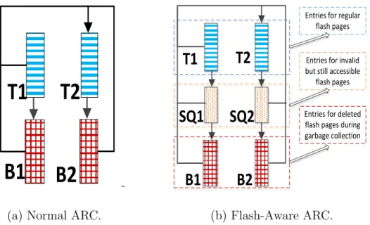
(b) Flash-Aware ARC. Fig. 3. Comparison between normal ARC and flash-aware ARC.
2.3.4 ARC-Based Flash-Aware Cache
Figure 3(b) describes our flash-aware ARC architecture. Similar to flash-aware LRU architecture, SQ will be added to buffer the evicted but still accessible data in flash memory. But there is a little bit of difference, SQ is split into SQ1 and SQ2 in accordance with T1 and T2. The total size of SQ1 and SQ2 is also defined by equation (4.2). Algorithm 2 shows our flash-aware ARC algorithm FARC. We use c denote the user-addressable physical flash capacity. p is the target size of T1. A Replace function is defined to replace an entry out based on the value of p at that time when a cache miss happens or cache hits in SQ1 or SQ2. Unlike the original ARC
algorithm, an entry evicted by the Replace function will be moved to SQ1 or SQ2
in our FARC algorithm. For any request, one of the six cases listed in algorithm 2 should happen. If a request hits in T1 or T2, the requested entry will be moved to the MRU position of T2 since it has been accessed twice recently. Another two cases: hitting in B1 and hitting in B2 will cause the adjustment of p. In this paper, we
follow the policy used in the original ARC algorithm to adjust the value of p. When
a request hits in B1, p will be increased by k1. If B1 contains more entries than B2,
then k1 is 1, otherwise, k1 equals the lengths of B2 over the lengths of B1. While a
request hits in B2, p will be decreased byk2. If the length of B2 exceeds the length of
B1, thenk2 will be 1, otherwise k2 will equal the length of B1 over the length of B2.
What’s more, the value of p will be confined to a range between 0 and c. In fact, due to the adoption of our flash-aware design, the adjustment of p could be performed a little bit differently. The total usable space in flash cache is not c, but c plus the
number of entries in SQ1 and SQ2 which we could callc‘. In the same way, the length
of T1 could be extended to include the SQ1 and the length of T2 could be extended to include the SQ2. As the length of SQ1 and SQ2 is unfixed due to the garbage
collection process, c‘, lengths of extended T1 and T2 are also fluctuant. Although
we could use these extended variables to make more accurate adjustment for p, we ignored these factors in our paper for the purpose of simplicity. We believe that this does not affect the cache performance too much because the queue lengths of SQ1 and SQ2 are much shorter than those of T1 and T2. After the recalculation of p, an entry will be replaced out and the requested entry will be moved to MRU position of T2 which also has been accessed at least twice recently. Also, the requested data is fetched from the lower-level storage and written to the cache. The forth case is that
a request hits in SQ1 or SQ2. An entry will be replaced out by calling the Replace
function unit. After that, the requested entry is moved from SQ1 or SQ2 to the MRU position of T2. If a request misses in all the queues, an entry from B1 or B2 will be
deleted and theReplace function will be called or an entry will be moved from T1 to
SQ1 as depicted in case V.
The bottom of algorithm 2 is the modified garbage collection process for our new ARC-based flash cache. Whenever a victim block is going to be erased, any page
inside it will be checked, if a page is buffered in SQ1 or SQ2, it should be discarded from SQ1 or SQ2 and moved to B1 or B2.
2.3.5 Discussions of Implementation Issues
One potential problem with our flash-aware design is the communication between the cache management and garbage collection process. Currently, most of the SSDs are designed as black boxes and FTLs including the garbage collection function units are running on embedded processors within SSDs. While the cache management unit that contains the cache queues are maintained by the OS on the host side. Therefore, the cache replacement algorithm running on the host side is unaware of the semantic information about garbage collection. What’s more, the address space in the cache queues is the addresses of underneath storage system, rather than the user-addressable space of SSDs. Hence, an additional mapping table should be maintained to translate the address space of the underneath storage system to the SSDs’ address space [22]. One possible way to bridge the gap is to merge the FTLs with the cache man-agement unit, either by opening the SSDs and moving FTLs into the host side like Triple-A [45], SDF [46] which has been widely deployed in Baidu’s storage system, and Fushion-io’s host based FTL [47], or moving the cache management units into the SSDs. By combining the cache management units with FTLs, the mapping ta-ble between underneath storage’s address space and SSD’s address space could be removed, and the mapping table inside the original SSDs can be merged with the cache queues by adding the physical addresses of flash memory to cache entries in the cache queues. Therefore, whenever a cache hit is detected through searching the cache queues, the corresponding physical location in the flash memory could be returned immediately. Moving FTLs to the host side has several benefits like performance enhancement, and cost reduction [45, 46, 47] due to the elimination of redundant
re-sources. The drawback is to consume additional host rere-sources. On the other hand, moving cache management units into the SSDs could deliver good flexibility but re-sult in higher requirement of the computing and memory resources inside SSDs. We adopt and implement the second solution in our simulations to verify the efficiency of our flash-aware design.
Another way is to design a special feedback interface which could expose neces-sary internal information of SSDs to the host side. A similar interface design has been utilized and proposed in [48] to support the nameless writes scheme which will return the physical address of the data inside SSDs to the host side after each write opera-tion (nameless write interface) or data migraopera-tion during garbage collecopera-tion processes (migration or call back interface). Moreover, a real prototype for the nameless writes scheme is implemented and evaluated on the OpenSSD Jasmine board in [49]. To make our flash-aware and zero-migration designs work, we can utilize the migration interface in the nameless writes scheme, whenever the garbage collection happens in-side SSDs, the feedback interface will send the LPNs of the invalid and valid pages in the victim block to the host side so that the cache management unit could eliminate the corresponding cache entries from the cache queues.
2.4 Experimental Methodology
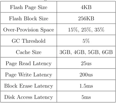
We modified the Disksim with SSD extension to evaluate our proposed flash-aware cache schemes [27]. Table 2 lists the main parameters of our experiments. Since LRU and ARC are two of the most widely used cache replacement algorithms to evaluate a cache architecture, we choose the normal LRU and ARC algorithms as our baselines and implement both of them with the Disksim simulator. Our flash-aware LRU, flash-flash-aware ARC, and zero-migration garbage collection algorithms as described in the previous section are implemented to show what benefits could be
Table 2. Configuration of Our Simulator
Flash Page Size 4KB
Flash Block Size 256KB
Over-Provision Space 15%, 25%, 35%
GC Threshold 5%
Cache Size 3GB, 4GB, 5GB, 6GB
Page Read Latency 25us
Page Write Latency 200us
Block Erase Latency 1.5ms
Disk Access Latency 5ms
obtained from our proposed schemes.
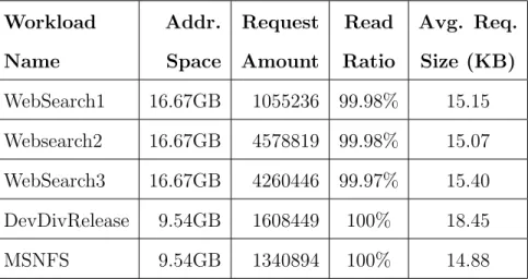
Five realistic workloads: WebSearch1, WebSearch2, WebSearch3, DevDivRe-lease, and MSNFS are used in our evaluation. WebSearch1, WebSearch2, and Web-Search3 were collected from popular search engines and nearly all the requests are read requests [50]. DevDivRelease and MSNFS are released by Microsoft [51]. De-vDivRelease was collected for developers tools release server. MSNFS was collected for MSN storage file server. Since our flash cache is used as a read cache, we only pick out the read requests from DevDivRelease and MSNFS as our test benchmarks. Details of the characteristics of these workloads are depicted in Table 8.
2.5 Experimental Results
Cache hit ratio, average response time, and erase count are three main metrics used in this paper to evaluate our proposed flash-aware and zero-migration garbage collection cache designs. The first subsection shows the results when only our flash-aware design is applied. Normal LRU, flash-flash-aware LRU, ARC, and flash-flash-aware ARC
0.00% 20.00% 40.00% 60.00% 80.00% 100.00%
Webs1 Webs2 Webs3 Dev MSNFS
Cache Hi t Ra ti o
LRU‐3G FLRU‐3G LRU‐4G FLRU‐4G LRU‐5G FLRU‐5G LRU‐6G FLRU‐6G
(a) LRU-15 0.00% 20.00% 40.00% 60.00% 80.00% 100.00%
Webs1 Webs2 Webs3 Dev MSNFS
Cac h e Hit Ra ti o
ARC‐3G FARC‐3G ARC‐4G FARC‐4G ARC‐5G FARC‐5G ARC‐6G FARC‐6G
(b) ARC-15 0.00% 20.00% 40.00% 60.00% 80.00% 100.00%
Webs1 Webs2 Webs3 Dev MSNFS
Cache Hi t Rat io
LRU‐2G FLRU‐2G LRU‐3G FLRU‐3G LRU‐4G FLRU‐4G LRU‐5G FLRU‐5G
(c) LRU-25 0.00% 20.00% 40.00% 60.00% 80.00% 100.00%
Webs1 Webs2 Webs3 Dev MSNFS
Cac h e Hi t R at io
ARC-3G FARC-3G ARC-4G FARC-4G
ARC-5G FARC-5G ARC-6G FARC-6G
(d) ARC-25 0.00% 20.00% 40.00% 60.00% 80.00% 100.00%
Webs1 Webs2 Webs3 Dev MSNFS
Cac h e Hit Ra ti o
LRU‐2G FLRU‐2G LRU‐3G FLRU‐3G LRU‐4G FLRU‐4G LRU‐5G FLRU‐5G
(e) LRU-35 0.00% 20.00% 40.00% 60.00% 80.00% 100.00%
Webs1 Webs2 Webs3 Dev MSNFS
Cac h e H it R at io
ARC-3G FARC-3G ARC-4G FARC-4G
ARC-5G FARC-5G ARC-6G FARC-6G
(f) ARC-35
Fig. 4. Cache hit ratios of LRU, FLRU, ARC, and FARC. The cache capacities used here include: 3GB, 4GB, 5GB, and 6GB. Over-provisions configurations are 15%, 25%, and 35%.
Table 3. Characteristics of I/O workload traces
Workload Addr. Request Read Avg. Req.
Name Space Amount Ratio Size (KB)
WebSearch1 16.67GB 1055236 99.98% 15.15
Websearch2 16.67GB 4578819 99.98% 15.07
WebSearch3 16.67GB 4260446 99.97% 15.40
DevDivRelease 9.54GB 1608449 100% 18.45
MSNFS 9.54GB 1340894 100% 14.88
as we have described previously are implemented and simulated to measure the results. The second subsection presents the results when our zero-migration garbage collection scheme is integrated with the normal and flash-aware caches.
2.5.1 Cache Hit Ratio
Cache hit ratio is a common metric to evaluate a cache’s performance and effi-ciency. Figure 4 shows our simulation results. For both LRU and ARC algorithms with multiple flash cache over-provision and capacity configurations, our flash-aware cache designs can achieve promising cache hit ratio improvement. For example, with 15% over-provision, our flash-aware LRU algorithm can increase the cache hit ratio by nearly 10% for WebSearch1 and WebSearch2 when the capacity is 3GB, while our flash-aware ARC design can obtain about 8% improvement in the best case. When over-provision is 25%, the cache hit ratio improvements could reach 19% and 12% for our FLRU and FARC, respectively. With 35% over-provision, FLRU and FARC could achieve about 28% and 21% cache hit ratio improvements in the best scenar-ios. Moreover, with the increasing of the over-provision, our flash-aware algorithms can gain more advantage over traditional algorithms. For example, for FLRU with
0 0.05 0.1 0.15 0.2 0.25 3G 4G 5G 6G Im pr ov em ent of Cac h e Hi t Rat io Cache Size FLRU‐15 FARC‐15 FLRU‐25 FARC‐25 FLRU‐35 FARC‐35
(a) LRU-15 0 0.1 0.2 0.3 0.4 3G 4G 5G 6G Imp rov emen t of ca ch e hit ra ti o Cache Size LRU ARC (b) ARC-15
Fig. 5. (a)Improvement of geometric means of cache hit ratios of FLRU and FARC with different over-provisions, baselines are normal LRU and ARC algorithms, and (b)Improvement of geometric means of cache hit ratios with the increasing of cache size. The over-provision configuration here is 15%. The cache hit ratios of 3G for LRU and ARC are used as our baselines for LRU and ARC respectively, all the results in the figure are the differences with the baselines. over-provision increasing from 15% to 35%, the geometric means of cache hit ratio im-provements are around 7.3%, 13.9%, and 20.3%, respectively, when the cache capacity is 3GB. For ARC, the results are similar. There are two reasons that make our flash-aware design obtain more benefits from larger over-provisions. On one hand, larger over-provision means more additional physical flash memory space for our flash-aware algorithm to explore to get more performance promotion. On the other hand, larger over-provision also means the user-addressable physical space is reduced when the total physical capacity is fixed, which will introduce more cache misses for normal LRU and ARC algorithms. Fortunately, our flash-aware algorithm can counteract the negative effects of cache misses. Besides, when the user-addressable physical capacity is large enough, for example when the over-provision is 15% and capacity is 6GB, the benefit from FLRU and FARC is limited. The reason is straightforward, larger capacity means higher cache hit ratio and less improvable space.
0 100000 200000 300000 400000
Webs1 Webs2 Webs3 Dev MSNFS
Numb e r of Er a s e s
LRU‐3G FLRU‐3G LRU‐4G FLRU‐4G LRU‐5G FLRU‐5G LRU‐6G FLRU‐6G
(a) LRU-15 0 100000 200000 300000 400000 500000
Webs1 Webs2 Webs3 Dev MSNFS
Nu m b e r o f Er ases
ARC-3G FARC-3G ARC-4G FARC-4G
ARC-5G FARC-5G ARC-6G FARC-6G
(b) ARC-15 0 50000 100000 150000 200000 250000
Webs1 Webs2 Webs3 Dev MSNFS
N u m b e r o f E r ases
LRU-3G FLRU-3G LRU-4G FLRU-4G
LRU-5G FLRU-5G LRU-6G FLRU-6G
(c) LRU-25 0 100000 200000 300000 400000
Webs1 Webs2 Webs3 Dev MSNFS
N u m b e r o f E r ases
ARC-3G FARC-3G ARC-4G FARC-4G
ARC-5G FARC-5G ARC-6G FARC-6G
(d) ARC-25 0 50000 100000 150000 200000 250000
Webs1 Webs2 Webs3 Dev MSNFS
N u m b e r o f E r ases
LRU-3G FLRU-3G LRU-4G FLRU-4G
LRU-5G FLRU-5G LRU-6G FLRU-6G
(e) LRU-35
0 100000 200000 300000
Webs1 Webs2 Webs3 Dev MSNFS
N u m b e r o f E r ases
ARC-3G FARC-3G ARC-4G FARC-4G
ARC-5G FARC-5G ARC-6G FARC-6G
(f) ARC-35
Fig. 6. Erase count collected from simulation of LRU, FLRU, ARC, and FARC. The cache capacities used here include: 3GB, 4GB, 5GB, and 6GB. Over-provisions configurations are 15%, 25%, and 35%.
LRU, but the FLRU can achieve similar or even better results compared with the FARC. Figure 5(a) shows the geometric means of cache hit ratio improvements of our FLRU and FARC algorithms under different flash capacities and over-provisions. It is very clear that LRU can acquire more benefits from our flash-aware design. The reason is that ARC has already done a very good job to cache the locality of workloads which will limit improvable space for our flash-aware design. Figure 5(b) presents the impact of cache size on geometric means of the cache hit ratio. Obviously, LRU can get more benefit from the increase of cache capacity. Since our flash-aware scheme works in a way similar to the expansion of cache capacity, LRU can get more performance promotion from our flash-aware design. Based on this observation, we may use the simple and low overhead LRU algorithm to get similar or even better performance of the ARC algorithm when our flash-aware design is utilized which will further boost the cache performance.
2.5.2 Impacts on Lifetime
In order to investigate how our flash-aware cache algorithms affect the lifetime of flash memory, we collected the erase count for all our experiments. Figure 6 presents our simulation results of erase count. The experimental results clearly show that our flash-aware cache design significantly extends the lifetime of flash memory. For example, our FLRU and FARC can at least reduce the number of erases by about 10% and 17% on average, respectively, when over-provision configuration is 15%. When the over-provision is 35%, the reduction could even reach nearly 72%. Thus the reduction of erase count is more significant than the improvement of cache hit ratios. One of the possible reasons is the write amplification effect of garbage collection processes. Before erasing a block, all the valid pages inside the victim block need to be moved to some new free space and this will introduce more additional writes. Then like the cascade
effect, more additional writes will trigger more garbage collection processes especially when used as caches which means more pressure from the upper-level requests.
What’s more, for all these four cache algorithms, higher over-provision will reduce the erase count even with the same total physical cache size. Although, higher over-provision means less user-addressable physical space and lower cache hit ratios for normal cache algorithms. Even for our flash-aware cache algorithms, the cache hit ratios will be a little bit lower with higher over-provision as the over-provisioning part will not always be filled with evicted data. There are two factors that affect the number of erase for a flash cache with a fixed total capacity: cache hit ratio, and over-provision. On one hand, lower cache hit ratio will introduce more writes to bring the missed data into the flash cache. On the other hand, higher over-provision gives the flash memory more space to delay and reduce the number and the overhead of garbage collection processes. From our experimental results, the reduction of erase count from higher over-provision counteracts the penalty from the reduced cache hit ratio.
From Figure 6, we also find that ARC and FARC suffer more erase operations compared with LRU and FLRU even under the cases in which they can achieve higher cache hit ratios. For instance, when the capacity is 3GB and the over-provision is 15%, for WebSearch2, the cache ratios for LRU and ARC are 41.87% and 50.4%, but the LRU suffers less than 300,000 erase operations, while ARC suffers more than 400,000 erase operations. We believe this is due to the multi-queue architecture of the ARC algorithm. Unlike LRU, ARC is divided into four LRU queues: T1, T2, B1, and B2. Cache entries will be moved among these queues, and also cache evictions can happen in both T1 and T2 based on the current cache condition. This multi-queue architecture may generate more data fragmentation which brings the mixture of valid and invalid pages within the same block. And this kind of data fragmentation
will introduce higher overhead for garbage collection processes since more valid pages need to be migrated.
2.6 Summary
In this chapter, we propose a novel flash-aware cache design. One of flash mem-ory’s most important properties is out-of-place update. When a flash memory is used as cache, cache evictions will generate superseded but still accessible data due to the out-of-place update property. Our flash-aware cache design takes advantage of these superseded but still accessible data to improve the performance and prolong the lifetime of flash cache. To evaluate the benefits of flash-aware cache design, we implemented the normal LRU, normal ARC, aware LRU (FLRU), and flash-aware ARC (FARC) cache algorithms on the Disksim simulator with SSD extension. Our simulation results demonstrate that our flash-aware cache can improve the cache hit ratio by up to 28%, reduce the average response time by up to 40% with higher performance stability, and alleviate the lifetime limitation of flash cache by reducing the erase count by up to more than 70%.
CHAPTER 3
ZERO-MIGRATION GARBAGE COLLECTION SCHEME FOR FLASH READ CACHE
3.1 Introduction
NAND Flash-based Solid State Disks (SSDs) have been deployed in a wide range of application scenarios including the portable devices, laptops, and high perfor-mance computing systems due to many attractive technical merits, such as low power consumption, light weight, shock resistance, sustain hot operation regimes, and ex-traordinarily high performance for random read access. But currently its still too costly to entirely replace the hard disks with SSDs, therefore SSDs are widely used as disk caches. Despite all these attractive merits, SSDs suffer from several inher-ent limitations, especially the limited erase cycles. Each flash block could only be erased limited cycles, after which the block will be unreliable and marked as bad. The lifetime issue becomes more serious with the shrinking of process geometries and adoption of MLC and TLC technologies. For TLC-based SSDs, each block could only sustain thousands of erase operations.
Garbage collections are internal activities of SSDs to reclaim the invalid pages generated by the out-of-place updates. A typical garbage collection process involves two steps to reclaim a victim block: data migration and erase. During the data mi-gration process, all the valid pages in the victim block need to be migrated to new
free locations before erasing the whole block, which will introduce Nvalid additional
page read and write operations. The data migration process have impacts on both the performance and endurance of SSDs. First, data migration process will introduce
extra latency and block the whole plane or package from servicing the requests from the outside. Moreover, the extra write operations incurred during the data migration processes will introduce more garbage collection and erase operations, therefore hurt the lifetime of SSDs. To reduce the cost of garbage collection process, we propose a new zero-migration garbage collection policy for Flash-based read cache, which elimi-nates the data page migration process and erases the whole victim block directly. The zero-migration garbage collection design are based on two observations. First, When flash memory is used as read cache, all the data in the flash memory has a backup in the write buffer or lower level storage device. Hence, the removal of valid data migration will never result in loss of data. Second, flash cache receives more pressure from the upper level requests. Therefore, any additional write operations during the garbage collection process will trigger more extra garbage collection processes in the future which will hurt both the performance and lifetime of flash cache.
PPN11 5 11 2 4 7 6 15 10 0 1 3 8 11 15 1 4 8 0 2 5 7 4->6 15->9 5->2 8->3 11->4 2->5 1->0 7->7 PPN0 BLK0 BLK1 BLK2 (Victim BLK)
5 11 2 4 7 free free free free
1 3 8 11 1 4 8 2 5 7 4->6 empty 5->2 8->3 11->4 2->5 1->0 7->7 BLK0 BLK1 BLK2 Mapping Table Cache queue Cache queue Mapping Table PPN0 PPN11 Zero-Migration GC 0->11 empty 0 15
Valid page Invalid page
del del
Fig. 7. An example to illustrate the working flow of our zero-migration garbage col-lection design.
3.2 Related Work
When SSDs are deployed as caches, endurance could be a big concern. Many previous work proposed solutions to prolong the endurance of SSD caches. Liu et al.
proposed DuraCache [52] to improve the endurance of MLC SSD based cache. When SSDs are deployed as write-through caches in data centers, DuraCache deals with the uncorrectable errors in SSD caches as cache misses to prolong the lifetime of SSD caches. Moreover, more ECC parities will be added to the data to provide stronger error tolerability when SSDs reach the wearout threshold. PLC-Cache [20] proposed by Liu et al. targets the deduplication-based primary storage system. When SSDs are deployed as caches atop a deduplication storage system, PLC-Cache achieve the lifetime extension by filtering out the unfrequent and unpopular accesses. Huang et al. proposed LACR [53] to extend the endurance of SSD cache by filtering our seldom accessed blocks and avoiding unnecessary cache replacements. Xia and Xiao proposed an Flash-aware cache design [26, 54] by leveraging the out-of-place update property to enhance the lifetime of SSD-based read cache.
3.3 Design and Implementation
Garbage collection algorithms are one of the key factors that will affect both the performance and lifetime of flash memories. In this section, we describe a new garbage collection method which aims to further improve the lifetime of flash-based read cache. Traditional garbage collection process consists of two parts: valid data migration and
flash block erase. The data migration process will introduces extra Nvalid read and
write operations, which hurts both the performance and lifetime of SSDs. However, when SSDs are used as read caches, all the data inside SSDs will have exact backups in the hard disks or write buffers. Therefore, we could aggressively skip the cost valid data migration processes and directly erase the victim block without causing any data loss, which is the main motivation of our zero-migration garbage collection scheme. Figure 7 is a simplified example to show the working flow of our zero-migration scheme. We assume there three victim block candidates, where each block has four
flash pages. To perform zero-migration garbage collection, the FTL selects a victim block using a specific garbage collection policies like the greedy algorithm, which is one of the most popular garbage collection algorithms and will be used in this work.
In this example,BLK2 has the largest number of invalid pages and will be selected
as the victim block. Then our zero-migration garbage collection policy will erase the victim block directly without migrating the valid pages inside the victim block, which are page 15 and page 0 in our example. Since the data residing in the valid pages in the victim block will not exist anymore after the whole victim block being erased, so we need to update the address mapping table and cache queue for synchronization. For all the valid pages inside the victim block, the corresponding entries in the cache queues will be deleted and the mapping information in the mapping table need to be invalidated. Moreover, we also integrate our zero-migration garbage collection scheme with our flash-aware cache design presented in the previous chapter.
Although aggressively remove all valid pages during garbage collection processes may have some negative impacts on the cache hit ratio, the overall performance like the average response time might be unaffected or even improved due to the reduction of garbage collection processes. Besides the basic zero-migration garbage collection design depicted above, we also implement a variant named conditional zero-migration design as a comparison which only deletes the relatively cold pages but keeps the hot pages. In our conditional zero-migration design, we treat the entries in the tail half of the cache queue as cold that will be removed during the garbage collection process, while entries in the head half of the cache queues are regarded as hot and will be migrated to other free locations during the garbage collection process. The result shows the conditional zero-migration garbage collection scheme can only achieve marginal improvement of the cache hit ratio (within 1%) with even worse average response time and limited extension on the lifetime when compared with the