Comparison of Neural Network NARMA-L2 Model Reference
and Predictive Controllers for Nonlinear Quarter Car Active
Suspension System
Mustefa Jibril1 Eliyas Alemayehu Tadese2
1.Msc, Department of Electrical & Computer Engineering, Dire Dawa Institute of Technology, Dire Dawa, Ethiopia
2.Msc, Faculty of Electrical & Computer Engineering, Jimma Institute of Technology, Jimma, Ethiopia
Abstract
Recently, active suspension system will become important to the vehicle industries because of its advantages in improving road managing and ride comfort. This paper offers the development of mathematical modelling and design of a neural network control approach. The paper will begin with a mathematical model designing primarily based at the parameters of the active suspension system. A nonlinear three by four-way valve-piston hydraulic actuator became advanced which will make the suspension system under the active condition. Then, the model can be analyzed thru MATLAB/Simulink software program. Finally, the NARMA-L2, model reference and predictive controllers are designed for the active suspension system. The results are acquired after designing the simulation of the quarter-car nonlinear active suspension system. From the simulation end result using MATLAB/Simulink, the response of the system might be as compared between the nonlinear active suspension system with NARMA-L2, model reference and predictive controllers. Besides that, the evaluation has been made between the proposed controllers thru the characteristics of the manage objectives suspension deflection, body acceleration and body travel of the active suspension system. . As a conclusion, designing a nonlinear active suspension system with a nonlinear hydraulic actuator for quarter car model has improved the car performance by using a NARMA-L2 controller. The improvements in performance will improve road handling and ride comfort performance of the active suspension system.
Index Terms--- Active suspension system, NARMA-L2 controller, model reference controller, predictive
controller
DOI: 10.7176/JIEA/10-3-04
Publication date: April 30th 2020
1 Introduction
The suspension system of a vehicle has two main operations. The primary one is to isolate the vehicle body from external road input profiles which occurs due to road disturbances. The secondary is to provide a balanced contact between the road and the tires. In a classical suspension system which it’s parameter only contains passive elements, the feats of rendering both ride comfort and road handling makes the system with low performance. To sustain the vehicle mass and to perfectly track the road, a stiffened suspension system is needed, but, to isolate the road disturbance a soft suspension is needed.
In general, all suspension system must provide the best ride comfort and road handling within a reasonable range of suspension deflection. Moreover, these criteria always depends on the parameters of the automobile. Race vehicles usually have high stiffness value, strong suspension with low performance ride quality while passengers vehicle have loosely suspensions with low performance road handling ability. From a system design idea, there are two main area of distraction on a vehicle, namely road and load disturbances. Road disturbances have the qualities of large magnitude in low frequency and small magnitude in high frequency. Load disturbances include the deviation of loads induced by accelerating, decelerating and cornering. Therefore, for the best suspension system design, care must be given to reduce the road disturbance to the outputs.
2 Mathematical Models
2.1 Mathematical modelling of nonlinear active suspension system
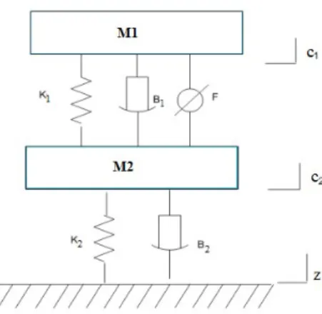
The quarter car model of nonlinear active suspension system is shown in Figure 1. The nonlinear active suspension system has the extra advantages which a terrible damping can be produced and producing the huge variety of force into the system at low velocities. Besides, this condition potentially will increase the overall performance of the suspension system. The derivations of mathematical equation of nonlinear active suspension system of quarter vehicle system are given through Eqs. (1) and (2).
Figure 1: Quarter model of nonlinear active suspension system. 3 1 1 1 2 1 1 2 1 1 2 1 1 2 1 1 2 1 2 1 1 sgn l nl l sym nl M c k c c k c c B c c B c c B c c c c F 3 2 1 1 2 1 1 2 1 1 2 1 1 2 1 1 2 1 1 2 1 2 1 2 2 2 2 2 sgn l nl l sym sym nl M c k c c k c c B c c B c c B c c B c c c c k c z B c z F
2.2 Hydraulic Actuator Design
The three by four-way valve-piston system is shown in Figure 2 is used for the hydraulic controller design. The pressure Hh from the actuator is given by Eqn. (3)
Figure 2: Hydraulic actuator
3
h L
H
AP
Where A (=Au, Area of upper chamber; = Al, Area of lower chamber) is the piston place and PL is the strain drop throughout the piston. The derivative of PL is given by Eqn. (4)
5 6
4
4
t L tp LV
P
Q R P
A y
y
Where Vt is the overall actuator volume,
is the powerful bulk modulus of the fluid, Q is the hydraulic load drift (Q = Qu+Ql), in which Qu and Ql are the flows within the upper and decrease chamber respectively and Rtp is the whole leakage coefficient of the piston. In addition, the valve load drift equation is given by Eqn. (5):
6 6 51
sgn
5
d SQ R x
P
y y
Where Rd is the release coefficient, is the spool valve vicinity gradient, y5 is the pressure inside the chamber of hydraulic piston and y6 = ysp is the valve displacement from its closed position,
is the hydraulic fluid density and Ps is the supply pressure, since, the term Pssgn
y y6 5may become negative, Equation (6) is replacedwith the corrected flow equation as,
6 5 6
6 5
1 sgn s sgn d S sgn 6 Q P y y Rx P y y 3 Road Profiles 3.1 Bump Road ProfileThe bump road profile input has a maximum peak of 10 cm as shown in Figure 3.
Figure 3: Random road profile
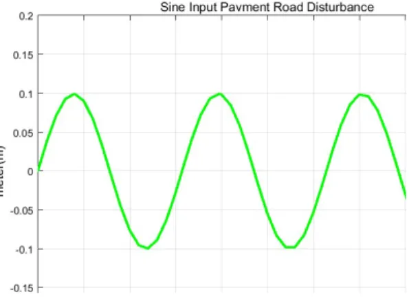
3.2 Sine Pavement Road Profile
The sine pavement road profile input has a maximum & minimum peak of 10 cm as shown in Figure 4.
Figure 4: Sine pavement road profile
4 The Proposed Controller Design
The design of NARMA-L2, model reference and predictive controllers are discussed as follow.
4.1 NARMA-L2 Controller Design
NARMA-L2 controller is used to become aware of the system to be controlled. Here in this system, we must train a neural network to represent the forward dynamics of the system. The NARMA-L2 Controller model is represented via a discrete time characteristic equation as shown in Eqn. 7.
Network Architecture
Size of hidden layer 9 Delayed plant input 3
Samp. interval(sec) 0.01 Delayed plant output 2
Training Data
Training sample 10000 Maximum Plant output 2
Maximum Plant input 4 Minimum Plant output 0
Minimum Plant input -1 Max interval value (sec) 1
Min interval value (sec) 0.1
Training Parameters
y (k d) f[y(k), , y(k n 1), u(k), , u(k n 1)] g[y(k), , y(k n 1), u(k), , u(k n 1)]
u(k 1) r 7
Which is realizable for d ≥ 2. The following Figure is a block diagram of the NARMA-L2 controller.
Figure 5. Block diagram of the NARMA-L2 controller
The neural network architecture, training data and training parameters for NARMA-L2, model reference and predictive controllers are shown in the Table 1 bellow
4.2 Model-Reference Controller Design
The designing of neural model reference control uses two neural networks: 1. A Neural network controller and
2. A Neural network controller for the plant model As shown in Figure 6 bellow.
Figure 6. Block diagram of the model reference controller There are three sets of controller inputs:
Delayed reference inputs Delayed controller outputs Delayed plant outputs
4.3 Predictive Controller Design
The design of model predictive controller is used to train a neural network to symbolize the forward dynamics of the plant. The prediction error between the plant output and the neural network output is used as the neural network training signal. The system is represented by the Figure 7:
5 Result and Discussion
The nonlinear quarter car active suspension system parameter values are shown in Table 2. Table 2: Parameters of nonlinear quarter vehicle model Model parameters symbol symbol Values
Vehicle body mass M 1 550 Kg
Wheel assembly mass M 2 63 Kg
Tire stiffness k 2 165,000 N/m
Suspension stiffness (linear) k1 36,000 N/m Suspension stiffness (nonlinear)
1 nl
k
3,600,000 N/mSuspension damping (linear) B1 1,200 N-s/m Suspension damping (nonlinear)
1 nl
B
800 N-s/mSuspension damping (asymmetrical)
1 sym
B
800 N-s/mTire damping B2 1,800 N-s/m
5.1 Control Targets Output Specifications
The control targets output specifications of the nonlinear quarter car active suspension system is shown in Table 3 below.
Table 3. Control targets output specifications No Control Targets Output
1 Body travel Minimum
2 Body acceleration Minimum
3 Suspension deflection Same as Road Profile
5.2 Simulation of a Bump Road Disturbance
The Simulink model for a bump input road disturbance including the nonlinear active suspension system with NARMA-L2, model reference and predictive controllers is shown in Figure 7 below.
Figure 7: Simulink model for bump road disturbance
The body travel, body acceleration and suspension deflection simulation output is shown in Figure 8, Figure 9 and Figure 10 respectively.
Figure 8: Body travel for bump road disturbance
Figure 9: Body acceleration for bump road disturbance
Figure 10: Suspension deflection for bump road disturbance
5.3 Simulation of a Sine Pavement Road Disturbance
The Simulink model for a sine pavement input road disturbance including the nonlinear active suspension system with NARMA-L2, model reference and predictive controllers is shown in Figure 11 below.
Figure 11: Simulink model for sine pavement road disturbance
Figure 13 and Figure 14 respectively.
Figure 12: Body travel for sine pavement road disturbance
Figure 13: Body acceleration for sine pavement road disturbance
Figure 14: Suspension deflection for sine pavement road disturbance
5.3 Numerical Values of the Simulation Outputs
The numerical values of the simulation output for the control targets body travel, body acceleration and suspension deflection is shown in Table 3, Table 4 and Table 5 bellow.
Table 3: Numerical values of the body travel simulation output No Systems Bump Sine
1 NARMA-L2 0.17m 0.2m 2 Predictive 0.3m 0.4m 3 M. Reference 0.7 0.7m
body travel amplitude in the bump & sine pavement road profile.
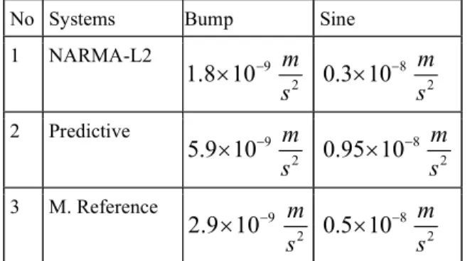
Table 4: Numerical values of the body acceleration simulation output
No Systems Bump Sine
1 NARMA-L2 9
1.8 10
2m
s
80.3 10
2m
s
2 Predictive 95.9 10
2m
s
80.95 10
2m
s
3 M. Reference 92.9 10
2m
s
80.5 10
2m
s
Table 4 shows us the active suspension system with NARMA-L2 controller have the minimum body acceleration amplitude in the bump & sine pavement road profile.
Table 5: Numerical values of the suspension deflection simulation output No Systems Bump Sine
1 Road Profile 0.1m 0.1m 2 NARMA-L2 0.12m 0.12m 3 Predictive 0.14m 0.15m 4 M. Reference 0.27m 0.17m
Table 5 shows us the active suspension system with NARMA-L2 controller have the suspension deflection amplitude the same as the road profile input in the bump & sine pavement road profiles.
6 Conclusion
In this paper, the mathematical model of the nonlinear active suspension system and the nonlinear hydraulic actuator was developed successfully. Matlab/Simulink model was designed for the NARMA-L2 , model reference and predictive controllers and comparisons of this proposed controllers have been done for the control targets (suspension deflection, body acceleration and body travel) using bump and sine pavement road profiles. The simulation results prove that the nonlinear active suspension system with NARMA-L2 controller shows a good response in minimizing the body acceleration and adjusting the suspension deflection and body travel vertical amplitude in both the road disturbances input. Finally, that the nonlinear active suspension system with NARMA-L2 controller shows a good improvement in ride comfort and road handling.
References
[1]. Mustefa Jibril et al. “Comparison of H∞ and μ-synthesis Control Design for Quarter Car Active Suspension System using Simulink” International Journal of Scientific Research and Engineering Development, Vol. 3 Issues 1, pp. 596-607, 2020.
[2]. Vineet Kumar et al.” Self-tuned Robust Fractional Order Fuzzy PD Controller for Uncertain and Nonlinear Active Suspension System” Journal of Neural Computing and Applications, Vol. 30, pp. 1827-1843, 2018. [3]. P. Senthil Kumar et al. “Adaptive Neuro Fuzzy Inference System Control of Active Suspension System with
Actuator Dynamics” Journal of Vibroengineering, Vol. 20, Issue 1, pp. 541-549, 2018.
[4]. D Wang et al. “Nonlinear Predictive Sliding Mode Control for Active Suspension System” Journal of Shock and Vibration, 2018.
[5]. B Abdi et al. “A New Approach to Optimal Control of Nonlinear Vehicle Suspension System with Input Constraint” Journal of Vibration and Control, 2018.
[6]. M Cui et al. “Random Modeling and Control of Nonlinear Active Suspension” Journal of Mathematical Problems in Engineering, 2017.
[7]. SA Chen et al. “Improved Optimal Sliding Mode Control for a Nonlinear Vehicle Active Suspension System” Journal of Sound and Vibration, 2017.
[8]. Imad A. et al. “A New Fuzzy-NARMA-L2 Controller Design for Active Suspension System” Basrah Journal for Engineering Science, Vol. 17, Issue 2 pp. 43-50, 2017.
[9]. S Bououden et al. “A Robust Predictive Control Design for Nonlinear Active Suspension Systems” Asian Journal of Control, 2016.