27 Page 27-35 © MAT Journals 2017. All Rights Reserved
Voice controlled Home Automation System with survellience
Using Smartphone
Ashish Agarwal, Lucky Sapam, Mohammad Zain, Rashmi Kumari T.Anushalalitha,Assistant Professor
Dept. of Telecommunication, BMSCE, Bangalore, India Email id - anusha.tce@bmsce.ac.in
Abstract
The objective of this paper is to discuss about a microcontroller based voice controlled automation home system using smartphones. The control applications are threefold. One is control of home appliances through switches operated with GSM module and the Bluetooth module and the other one being voice controlled vehicle robot achieved using Arduino and Arduino Uno microcontrollers.
Keywords: Home automation; GSM; Arduino,Arduino Uno, voice controlled robot
INTRODUCTION
Mankind has always looked forward to make our lives easier day by day by using various automatic appliances which reduces human effort to do any work. In our project we have tried to build one of the automatic system that ease human work that is “voice controlled home automation system”.
Basically home automation means getting access to control devices in our home which uses electricity from a mobile device anywhere in the world. This can be achieved by many ways like using GSM module for larger range , Bluetooth for shorter range and also get physical access of any home stuff without going there and picking it up which can be done using voice controlled robotic vehicle .These can be achieved by voice command or text message. We have included three module to achieve complete home automation system.
It is microcontroller based voice controlled home automation system using smart phone or GSM phone .The user just need to have an android or simple GSM phone and a control circuit which comprises of Arduino Uno microcontroller.
The project is mainly aimed to comfort the physically challenged people who cannot go and operate devices .They can just operate it through voice command or using an android application.
Guidelines for using Arduino board-The various prototyping of the design and the scope of Arduino are well understood. The reading of the input, the light sensor and interfacing Bluetooth , GSM to Arduino are well understood.
“Smart homes for better living using Bluetooth communication based on atmega microcontroller” by Monika rana, Ramandeepsingh
“Home automation system –A study” By Satish Palaniappan and naveenhariharan
METHODOLOGY
Our project “Voice controlled home automation system” consists of three modules as follow:-
1. GSM module 2. Bluetooth module
3. Voice controlled robotic vehicle
The complete block diagram consisting of all three modules are as follow
28 Page 27-35 © MAT Journals 2017. All Rights Reserved Fig: 1 Basic block diagram of home automation system
GSM MODULE HOME
AUTOMATION SYSTEM
In this module, arduino is utilized for controlling the entire procedure. We have utilized GSM remote correspondence for controlling home apparatuses. We send order to control home apparatuses. These orders will resemble "#A.light on*, "#A.light off* et cetera. After Arduino gets orders through GSM, Arduino sends flag to transfers to kill the machines ON and utilizing hand-off driver.
“#A” Prefix used in command string is to identify main command is coming next to
it and * used in the string indicates the end of the message.
When any message is sent to GSM module through mobile phone, then SMS is read by Arduino and extract main command from it and store it in variable. Then received string is compared with the predefined string. In the event that string matches then Arduino send motion for working home apparatuses through switches controlled by transfers with the assistance of hand-off ICs for ON/OFF operation. Relative status and results are shown on 16*2 LCD show.
Fig1: Block diagram of GSM home automation system Arduino uno is the heart of our project that
has 16 input/output pins. The input signal
received by various modules is interpreted by arduino and perform accordingly.
29 Page 27-35 © MAT Journals 2017. All Rights Reserved GSM module-GSM module remains for
worldwide framework for versatile correspondence. It is for the most part utilized for portable correspondence between a PC and a GSM –GPRS framework . GSM design is by and large utilized for portable correspondence. ULN2003-ULN2003 is an array of seven NPN darlington transistor produces 500mA , 50V output .It is mainly known for high current and high voltage capacity. It uses common flyback diodes for switching inductive loads.
16*2 LCD can display 16 characters in one line.
The input signal received by various module is interpreted by arduino and perform accordingly. The pin diagram of the Arduino uno shows the digital i/o pins containing 6 PWM o/ps,6 analog o/ps,16MHZ crystal oscillator,power jack,rest button and a GSM connection. GSM module is a design utilized for versatile correspondence comprising of GSM modem consolidated together with power supply circuit and correspondence interfaces. Sole of such module is modem. The GSM module provides network connectivity between the GSM and the computer.
Table1: AT commands for GSM operation
Sl.No AT Commands Function
1 ATA Answering calls
2 ATD Dialling a call
3 AT+CMGR Reading a message
4 AT+CMGS Sending SMS
It understands only AT commands is if GSM is working properly it responds “ok” or else “ERROR” . It should be followed
by carriage return i.e \r (OD in hex) like “AT+CMGS\r”.
Fig2: Circuit diagram of GSM module
GSM based home automation circuit connection are quite simple. LCD display which is used to display the states of home appliances is connected to Arduino in 4 bit mode.
30 Page 27-35 © MAT Journals 2017. All Rights Reserved Table2: Arduino pins and modes of operation
Digital pin Mode
6 RS 7 EN 8 D4 9 D5 10 D6 11 D7
Rx and Transmitter pin of GSM module is connected to Transmitter and Rx pin of Arduino respectively. 12 volt adapter is used as power source for GSM module.
Light, fan, water level controller are controlled using three 5 volt SPDT relays. Relay driver are connected to pin 3, 4, 5 of Arduino through relay driver ULN2003. Flow Chart
Fig 3.Flow chart
BLUETOOTHMODULE
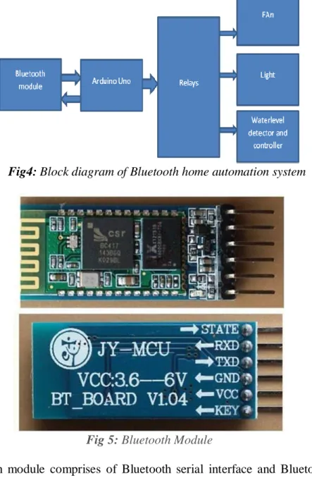
31 Page 27-35 © MAT Journals 2017. All Rights Reserved Fig4: Block diagram of Bluetooth home automation system
Fig 5: Bluetooth Module
HC_05 Bluetooth module comprises of Bluetooth serial interface and Bluetooth adapter to convert serial port to Bluetooth.It consists of 12.7mm*27mm small footprint and provides wireless connectivity.
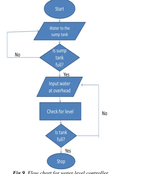
32 Page 27-35 © MAT Journals 2017. All Rights Reserved Fig7.Flow chart
Water level Controller
Fig8: Circuit diagram of water level detector and controller In the circuit,we have used conduction of
current using five aluminium wires to measure the level of water, that is ¼, ½, ¾, and full levels for sensing the level of water in the tank and a fifth one attached to the bottom. Analog input pins of Arduino
is connected to the other dry ends of these wires. And a fifth wire is fixed at bottom of the tank and wire is made to stay there. R6 to R5 - pull down resistors. +5V DC of Arduino is supplied to the resistors through dry ends of wires. Tank is filled by water
33 Page 27-35 © MAT Journals 2017. All Rights Reserved slowly and when water touches a particular
wire it makes electrical connection to it and conducts electricity between the probe and +5v probe since water is conductor of electricity and current flow through it determines the waterlevel as there is corresponding voltage drop across the pulldown resistors. Level of the sump tank is measured using same method.
Different functions are performed by various pin of Arduino and therefore digital pins of Arduino controls buzzer and the motor which is water pump. Buzzer is driven by transistor Q1 and base current across transistor is controlled by resistor R5. Relay is driven by transistor Q2 and base current across it is controlled by resistor R3. D2 in the circuit is freewheeling diode. Contrast of LCD is
controlled and maintained by POT or potentiometer. Resistor R1 is used to limit the current through the power on LED. Using analogRead function sensor output is read through input pins of arduino. This function converts the voltage into a number and stores it in a variable. For identifying the current condition of probe these variables are compared to a fixed number and if the voltage at particular sensor is greater than this value , then it is considered as an electrical continuity and water is assumed to be touching the end of probe and hence the conduction. 9V external jack is used to power the circuit or it can be directly fed from computer through USB cable. The 5V supplyneeded can be tapped from the 5V output on the
Arduino board.
34 Page 27-35 © MAT Journals 2017. All Rights Reserved With the implementation of the system of
considered design the result of water level at various marked point. The water pump will completely shut and buzzer will sound when water is at highest point. The buzzing sound is made only after when water level is full and not at any other level. Whatever is the level in water tank it is displayed on 16*2 LCD whether it is medium, high, low and full. Source tank or sump tank is also connected to arduino to make sure that
process of stopping water takes place. The automation of the water pump is connected to the highest level of water where it cuts off the supply of the signal to the water pump and it shuts down. The alarm system of both the buzzer and indication makes us aware of the process os controlling water level without any manual work. This helps us to conserve water and avoid wastage of water and makes lifestyle easy.
VOICE CONTROLLED ROBOTIC VEHICLE
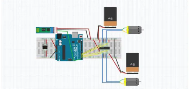
Fig10: circuit diagram of voice controlled vehicle robot Voice controlled vehicle robot part of the
project help us to control robot through voice commands received via android application. The voice commands are read
and captured through integration of control unit with Bluetooth device. The robotic vehicle then operates according to the command received via android application.
Fig 11 Robotic vehicle The controlling device can be any android
based smart phone /tab using android operating system. A good interactive GUI is provided by android controlling system which makes easy for the uses to control the vehicle. The data is transmitted using a transmitter which uses android application.
The commands transmitted by transmitter is received and read by receiver which is then interpreted into controlling robotic vehicle. The command sent by android device is to move vehicle in forward, backward, right and left direction. After receiving the commands motor driver IC is operated by arduino in order to move vehicle in four directions. The Arduino is
35 Page 27-35 © MAT Journals 2017. All Rights Reserved programmed to move the motor through
motor driver IC.
CONCLUSION
With the implementation of our project voice controlled home automation with surveillance according to our considered design we are successfully able to automate electronic appliance of a home through our voice commands.
We have achieved home automation for short and long range as well using Bluetooth and GSM module. A voice command is given through android phone which is then interpreted by arduino which results in turning appliances OFF and On accordingly. In order to achieve home automation for long range we have used GSM module for controlling home appliances from longer range. A robotic vehicle is used in our project for surveillance for getting access to home stuff which works on voice command. Automating the home appliances through voice has been interesting a lot of people from long time. There is a need of a system which can be used to control the electronic appliances of home without being present at home and also keep an eye on home.
This project presents a home automation system with surveillance. The goal of this project is to design and implement an embedded system which can easily interface the existing home appliances and
communicate via smart phone or GSM phone and also enhance security of home through surveillance.
The technology used in our project could be used in wide variety of appliance that need sensor and appliances and can serve society in a very instructive way. This technology can be extended to automate even non-electrical device of home and automate each and every task of home. Instead of using just Bluetooth and GSM we can design a web page to control particular appliances from any part of world. REFERENCES http://www.engineersgarage.com/contr ibution/home-automation-system-using-gsm-and-arduino http://www.instructables.com/id/Ardui no-Home-Automation-Bluetooth/?ALLSTEPS http://www.instructables.com/id/Bluet ooth-home-automation-with-arduinoVOICE/?ALLSTEPS http://www.engineersgarage.com/articl es/gsm-gprs-modules https://en.wikipedia.org/wiki/ULN200 3A http://www.androidmines.com/2016/01 /voice-controlled-project-using.html http://circuitdigest.com/microcontroller -projects/gsm-based-home-automation-using-arduino