Design and Application of Superconducting Fault
Current Limiter in A Multi-terminal HVDC System
Qingqing Yang, Simon Le Blond, Fei Liang, Min Zhang,
Weijia Yuan, Jianwei Li
Abstract—Voltage source converter based HVDC (VSC-HVDC) systems are prone to high short circuit current during transmission line faults. The situation for multi-terminal HVDC (MTDC) systems is worse. The characteristics of superconducting material are ideal to limit the fault current in HVDC systems. This paper presents a novel use of the resistive type of Superconducting Fault Current Limiter (SFCL) in the multi-terminal HVDC network with the function of limiting the high current. The working principles of fault current limiter and a three-terminal HVDC system are modelled in detail using PSCAD/EMTDC software. The hybrid operation of the SFCL in the three-terminal HVDC system is tested in this paper for the fault response of the MTDC system. The performances of SFCL under different fault conditions are analysed. The simulation results show that the fault current is effectively restrained and the SFCL can act as an efficient protective device for VSC based multi-terminal HVDC systems.
Index Terms—DC line fault, dynamic analysis, multi-terminal VSC-HVDC, PSCAD/EMTDC, superconducting fault current limiter.
I. INTRODUCTION
VDC, especially multi-terminal HVDC systems have become a more and more attractive option for power system transmission [1]. VSC-HVDC technologies have been widely used in multi-terminal HVDC systems because of its full controllability [2]. A series inductor connected with the line in current source converter based HVDC (CSC-HVDC) can naturally withstand short circuit faults, but not applied in VSC-HVDC systems [3]. Compared with the traditional VSC-HVDC system, VSC-HVDC is subjected to high short circuit fault current caused by DC transmission line faults [4]. In addition, the DC fault current rises much more rapidly in MTDC system and has larger magnitude compared with the point-to-point HVDC systems [5].Hence, the studies related to limit fault current for HVDC transmission system (especially the one using VSC technology and multi terminal converter stations) is necessary.
In many cases, shunt reactors (inductors) are used to decrease fault current while the fixed impedance in these devices will reduce system efficiency and may impair system stability [6]. Fault current limiters (FCLs) are developed with the capability of rapidly increasing their impedance, and thus limiting high fault currents. Superconducting fault current limiters (SFCLs)
The authors are with the Department of Electronic and Electrical Engineering, University of Bath, Bath BA2 7AY, U.K. (e-mail: [email protected]).
utilize superconducting materials to limit the fault current directly and improve power system reliability and stability.
Various design technology of FCL has been considered, the resistive SFCL, saturable-core SFCL, shielded-core SFCLand non-superconducting technologies. The FCL based on superconducting technology relies on the transition of superconductor from superconducting state to normal state (quenching process) and the non-superconducting technologies use DC HTS magnet windings to saturate an iron core [6]. For HVDC systems, the resistive SFCL is commonly designed as proposed in paper [7-9]. However, other types of SFCL are still applied in HVDC systems, such as the flux-coupling type of SFCL are used in [10]. A hybrid type of superconducting circuit breaker is introduced in [5]. For simplicity and reliability, the resistive SFCL is applied and studied in this paper.
The main purpose of this paper is to design and simulate the resistive types of SFCL, which have been applied in a three-terminal HVDC system. This research has emphasized the feasibility of SFCL in multi-terminal HVDC systems. An SFCL can suppress the large DC fault current in MTDC system to breakable values during the response time of DCCB and significantly reduce the current interruption stress on DCCB components.
II. SUPERCONDUCTING FAULT CURRENT LIMITER Resistive type SFCL is one of the most promising SFCLs due to its simplicity, low weight, and volume. A low impedance value will be kept under normal operation and a higher value will be transformed during fault conditions. The resistance of SFCL is almost zero with the negligible influence on the system in normal operation [11]. The increased impedance makes the current decreasing to levels below the breaker limit during a fault situation, which can effectively reduce the fault current in the DC system [4]. In addition, the stability margins of the system will be enhanced by applying SFCL.
The performance of an SFCL is dominated by the interaction between High Temperature Superconductors (HTS) electromagnetism and thermal physics. With the second generation Yttrium barium copper oxide (YBCO) coated conductors, the SFCL can be built with high current density as well as fast transition and recovery. The wire used in this paper is 12 mm width and 0.15 mm thickness with 250 A rated current. The resistance is 0.104 Ω/m. 6 wires with 120 Ω resistance is in parallel, hence the total resistance is 20 Ω. The critical current is 1.5 kA in SFCLs.
state, which are temperature (T), magnetic field (H) and current density (J). A 3-D phase diagram (Fig.1) is generated to present the characteristics of the dependencies for HTS. The modes of operation of the SFCL can be described in three states: superconducting state, flux flow state, and normal conductor state, according to the value of the resistance, in addition to the recovery to the superconducting state.A maximum value can be reached when the other two critical parameters are set to be 0. The volume from the origin to the inner surface is regarded as the superconducting region. The variation of any of these three parameters can bring a transition between the superconducting and the normal conducting regime.
Fig. 1. 3-D phase diagram
Electrical field and current density, which is known as E-J Power Law, as shown in Fig. 2, of HTS, is the best way to describe the electromagnetic properties of SFCLs. 𝑐 and 𝑐 represent the critical current and the critical current density respectively. 𝑐 is normally defined as the current density value where the electric field E in the superconductor is 1 V/cm for simplicity and consistency. The critical current of the developed model is set to 1 kA. YBCO coated conductors usually have large n value of E-J power law[12]. Any current transient which exceeds critical current𝑐 will trigger the quench operation of the model.The flux flow resistance will increase in a step form within the first half cycle of the fault current. This piecewise linear conductance property is implemented in the simulation work to simulate the related SFCL. Therefore, the developed model of SFCL on PSCAD/EMTDC is represented as a constant resistance. The DC current is used to determine the critical point at which the SFCL will be converted to normal conducting state.
Fig. 2.E-J curve of HTS [13]
Because superconductors possess highly non-linear properties, superconductors are used to limit peak currents which depend on the non-linear response to temperature, current and magnetic field variations. The resistance transition of superconducting tapes in terms of temperature and current density is the best way to describe the characteristics of the
resistive type SFCL current limiting behavior (equation 1)[12].
𝑅𝑆𝐹𝐶𝐿= {
0 𝑓 [ 𝐽𝐽
𝑐 𝑛
] 𝑓 𝑇
< 𝑐, 𝑇 < 𝑇𝑐
> 𝑐, 𝑇 < 𝑇𝑐
𝑇 > 𝑇𝑐
(1)
Where: J is the current density of superconductor, T is the temperature, 𝑇𝑐 and 𝑐 represent the critical temperature and the critical current density respectively, and n represents the exponent of E-J power law relation.
The critical current density of superconductor is [11]: Jc= Jc Tc−T
Tc−T α
(2) Where Jc is the critical current density of superconducting at the initial temperature T , α is the cross-sectional area of the superconducting material and Tc is the critical temperature.
When the current exceeds the critical current, the resistivity starts to increase to very high values according to the following equation:
ρc=E0 Jc
J Jc
N− , T < T
c , J > Jc (3) Then, the temperature of the YBCO is calculated as follows: T t = T +
C ∫ Q c t dt (4) Where: Qc is the net energy in the superconducting windings, T is the initial temperature of the material and C is the heat capacity of the material which describes the amount of heat needed to increase the material temperature by one degree.
In equation 1, when the condition J < Jc, T < Tc is met, the SFCL will be in superconducting state which represents zero resistance. SFCL will transition to flux flow state when J > Jc,
T < Tc. When the temperature reaches its critical value (T >
[image:2.612.313.565.489.666.2]Tc), the status will be in the normal resistive mode. Based on the superconducting features, the SFCL model is established in PSCAD/EMTDC. The DC current measured on both ends of the transmission line is used to determine the critical point. The superconducting resistance is a constant for different states and can be calculated for each transition to a new state.
Fig. 3. SFCL model in PSCAD/EMTDC
[image:2.612.57.283.542.665.2]used to detect the mode of the SFCL by determining the critical temperature and critical current density. SFCL model compares the value of the incoming current with the setting current value. If the incoming current is less than the triggering current, the SFCL remains at minimum impedance. On the other hand, the SFCL will reach to higher impedance if the incoming current value is more than the triggering current.
III. THE MTDC SYSTEM MODELLING
[image:3.612.332.547.51.195.2]A three-terminal VSC based HVDC system on the basis of CIGRE B4 programme [14] is developed in PSCAD/EMTDC software shown in Fig. 3 (parameters in Table 1). For all transmission links a 200 km long overhead line with frequency- dependent model, which is illustrated, is adopted in this paper.
Fig. 3. The configuration of three-terminal HVDC system Table 1 Nominal parameters of the simulated test system
Parameter Nominal Value
Rated power 100 MVA
DC link voltage ±40 kV
R, L, C of DC overhead lines
10mΩ/km, 0.56mH/km, 0.26µF/km
DC terminal reactor 300 mH
L-filter impedance (r+jωL) (0.01+j0.25) p.u. Line-line AC voltage 24.5 kV
Two series capacitors 600 μF
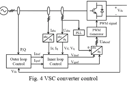
VSC based converter station control is presented in Fig. 4. VSC-HVDC systems function as an ideal voltage source at the DC terminals and can be connected in parallel without posing any technical difficulties [15]. The AC voltage waveform is synthesized using a two-level approach. In the established network, terminal 3 works as the sender to terminal 2. In addition, terminal 2 transport power to terminal 1.
Once the DC line fault occurs, the DCCBs operate and cut the fault at both ends of the line to keep stable operation with no power losses. Two SFCLs are applied at two ends of the transmission lines working together with circuit breakers. The main function of SFCL in DCCB is to suppress the increasing DC fault current to a lower level and significantly reduce the current interruption stress on DCCB components.
Fig. 4 VSC converter control
[image:3.612.47.299.227.373.2]IV. SIMULATION RESULT AND DISCUSSION In order to investigate the performance of multi-terminal VSC-HVDC system in Fig. 3 with the designed SFCL model, various simulation situations are carried out for the DC line faults on different sections and AC faults on different terminals. Pole to ground faults (Position A), pole to pole faults (Position B) and AC side faults (Position C) were simulated with different fault resistance as shown in Fig. 3. The fault is applied at 6 s and lasts 0.05 s. The time step chosen for the simulations is 50 μs, which will provide a high fidelity transient response. The first case is applying a DC line to ground fault for 50 ms duration. The fault is set at the positive pole and 40% of total line distance from terminal 1 with 0.01 Ω fault resistance.
Fig. 5. Positive pole ground fault
The operating characteristics of SFCL when HVDC line to ground fault occurred are shown in Fig. 5. For better understanding and analysing the result, the p.u. system is used in this paper and the base value is selected to be 1 kA. As depicted in Fig. 5, the peak fault current can reach up to approximately 4.75 times of the normal DC current on the faulted pole, and 2 times on the healthy pole. With SFCL applied on both ends of the transmission line. It is shown that, with SFCL, the current peak is limited to about 2.51 p.u, while the prospective current is 3.82 p.u. on positive pole. This means the fault current is limited to 35% from the fault condition without SFCL.
[image:3.612.331.545.364.548.2]features of curve. 5.76 p.u. can be reached during a fault, which is 7 times the original current. With SFCL the fault currents can be limited to 65% for both ends and poles.
Fig. 6.Pole to pole fault
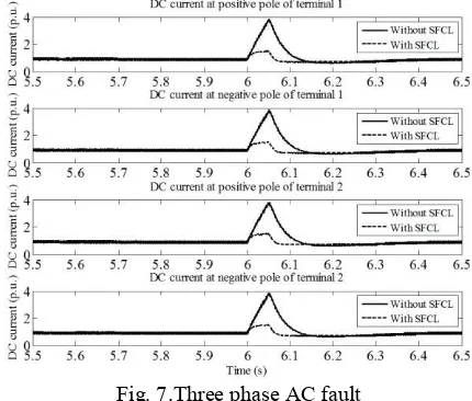
Using a three phase AC fault as an example, Fig. 7 shows the HVDC transmission line DC current under these conditions. In this case, 3.96 p.u. of maximum transient fault current on DC transmission line was observed. When SFCLs were applied, simulation result of DC current of transmission line was drastically decreased to 1.89 p.u., which means 50% fault current is limited by the SFCL.
Fig. 7.Three phase AC fault
On a healthy link, the system response with and without SFCL are similar. As can be seen in the Fig. 5 with a positive-ground fault applied, the negative pole which is the healthy pole in the system has little impact on the waveform with the designed SFCL compared with the waveform without SFCL.
Through the analysis of the simulation results, the resistive SFCLs can effectively limit the first peak of fault current. The SFCL responds quicker than the rest of the protection system and therefore can be complementary to circuit breakers reducing the fault current breaking requirement. A resistive type of SFCL is intrinsically safe with compact size compared with other fault current limiters. The promising DCCB technologies still have significant shortcomings in terms of on-state losses or speed. SFCLs are characterized by a very rapid transition from zero resistance to their nominal conducting resistance once a critical current density is reached. The fault
current in HVDC system which only have resistance but no impedance effect will be very large compared to AC systems and the situation in MTDC system is more severe compared with point-to-point system. The most important thing need to be emphasized is the high limitation level (up to 80%). HTS SFCL could also reduce the loss during normal conditions, while IGBT DC breakers loss could not be neglected [16]. The necessity of adding SFCL is that resistive types of SFCL have a better performance suppressing the large fault current. The damage to the system caused by DC transmission line fault will be significantly reduced, and the equipment will be protected from the high raised fault current. In addition, limiting fault current reduces the consequent voltage disturbances on the healthy parts of the system due to a fault. Mitigating these disturbances can help both load and generation ride through the fault. Consequently, the presence of an SFCL can lead to improved overall reliability for other devices in distribution systems.
The main elements affecting the cost of DC circuit breaker is the total fault clearing time which consists of the breaking time and fault clearing time and the reactor. A longer breaking time can lead to a very high level fault current which means a greater current breaking capability. Therefore, shorter breaking time is more desirable. The cost of SFCL depends on its current limiting capability. The investment for both devices can be very expensive. Combination of these two devices maybe a beneficial solution such as a combination of lower current limiting capability SFCL and a higher current breaking capability HVDC circuit breaker.
V. CONCLUSION
This paper has successfully integrated and evaluated the performance of VSC based multi-terminal HVDC system with resistive SFCL. An effective model of resistive type of SFCL has applied in VSC based multi-terminal HVDC system, considering the DC breakers overcurrent withstand capability. Based on the electric field intensity and current density characteristics, the SFCL has been modelled in this paper and it is successfully integrated into a VSC based MTDC system for fault current limitation under AC/DC faults. The transient analysis is carried out for different perturbations and from the simulation results. Simulation results show that SFCL not only reduces the current transients for DC faults but also for AC faults. The method was validated by time domain simulations undertaken with the PSCAD/EMTDC, and the results showed that the fault current could be reduced up to 65%. The use of SFCL can effectively suppress the short circuit fault on DC line. Hence, the robustness of VSC based multi-terminal HVDC system can be improved against the DC fault to a certain extent. The DC resistive SFCL is proved to be a very promising technology in multi-terminal HVDC systems.
REFERENCES
[image:4.612.64.279.362.545.2]HVDC systems," Renewable and Sustainable Energy Reviews, vol. 56, pp. 965-974, 2016.
[2] C. Dierckxsens, K. Srivastava, M. Reza, S. Cole, J. Beerten, and R. Belmans, "A distributed DC voltage control method for VSC MTDC systems," Electric Power Systems Research, vol. 82, pp. 54-58, 2012. [3] N. Flourentzou, V. G. Agelidis, and G. D.
Demetriades, "VSC-Based HVDC Power Transmission Systems: An Overview," Power Electronics, IEEE Transactions on, vol. 24, pp. 592-602, 2009.
[4] F. A. Mourinho, D. Motter, J. C. Vieira, R. M. Monaro, S. P. Le Blond, M. Zhang, et al., "Modeling and analysis of superconducting fault current limiters applied in VSC-HVDC systems," in 2015 IEEE Power & Energy Society General Meeting, 2015, pp. 1-5. [5] U. A. Khan, J.-G. Lee, F. Amir, and B.-W. Lee, "A
Novel Model of HVDC Hybrid-Type Superconducting Circuit Breaker and Its Performance Analysis for Limiting and Breaking DC Fault Currents," IEEE Transactions on Applied Superconductivity, vol. 25, pp. 1-9, 2015.
[6] S. Eckroad, "Superconducting fault current limiters,"
Electric power research institut, vol. 1017793, 2009. [7] Y. Chen, X. Liu, J. Sheng, L. Cai, Z. Jin, J. Gu, et al.,
"Design and application of a superconducting fault current limiter in DC systems," IEEE Transactions on Applied Superconductivity, vol. 24, pp. 1-5, 2014. [8] H.-J. Lee, G. T. Son, J.-I. Yoo, and J.-W. Park, "Effect
of a SFCL on commutation failure in a HVDC system," IEEE Transactions on Applied Superconductivity, vol. 23, pp. 5600104-5600104, 2013.
[9] J.-G. Lee, U. A. Khan, J.-S. Hwang, J.-K. Seong, W.-J. Shin, B.-B. Park, et al., "Assessment on the influence of resistive superconducting fault current limiter in VSC-HVDC system," Physica C: Superconductivity, vol. 504, pp. 163-166, 2014. [10] L. Chen, H. Pan, C. Deng, F. Zheng, Z. Li, and F. Guo,
"Study on the Application of a Flux-Coupling-Type Superconducting Fault Current Limiter for Decreasing HVdc Commutation Failure," Canadian Journal of Electrical and Computer Engineering, vol. 38, pp. 10-19, 2015.
[11] F. Liang, W. Yuan, C. A. Baldan, M. Zhang, and J. S. Lamas, "Modeling and experiment of the current limiting performance of a resistive superconducting fault current limiter in the experimental system,"
Journal of Superconductivity and Novel Magnetism,
vol. 28, pp. 2669-2681, 2015.
[12] M. E. Elshiekh, D.-E. A. Mansour, and A. M. Azmy, "Improving fault ride-through capability of DFIG-based wind turbine using superconducting fault current limiter," IEEE Transactions on Applied Superconductivity, vol. 23, pp. 5601204-5601204, 2013.
[13] W. Paul, M. Chen, M. Lakner, J. Rhyner, D. Braun, and W. Lanz, "Fault current limiter based on high temperature superconductors–different concepts, test
results, simulations, applications," Physica C: Superconductivity, vol. 354, pp. 27-33, 2001.
[14] T. K. Vrana, Y. Yang, D. Jovcic, S. Dennetire, J. Jardini, and H. Saad, "The CIGRE B4 DC grid test system," System, vol. 500, p. D1, 2013.
[15] T. Hammons, D. Woodford, J. Loughtan, M. Chamia, J. Donahoe, D. Povh, et al., "Role of HVDC transmission in future energy development," IEEE Power Engineering Review, vol. 20, pp. 10-25, 2000. [16] C. Peng, J. Wen, Y. Wang, J. Wu, and X. Chen,
"Potential use of fault current limiter in VSC based DC transmission systems," in 2012 Asia-Pacific Power and Energy Engineering Conference, 2012, pp. 1-4.
![Fig. 2.E-J curve of HTS [13]](https://thumb-us.123doks.com/thumbv2/123dok_us/1500712.102795/2.612.100.248.199.319/fig-e-j-curve-of-hts.webp)