ROSPlan: Planning in the Robot Operating System
Michael Cashmore, Maria Fox,
Derek Long, Daniele Magazzeni,
and Bram Ridder
King’s College LondonLondon WC2R 2LS [email protected]
Arnau Carrera
a, Narc´ıs Palomeras
b,
Nat`alia Hurt´os
b, and Marc Carreras
aUniversity of Girona 17071 Girona, Spain afirstname.lastname@udg.edu
bnlastname@eia.udg.edu
Abstract
The Robot Operating System (ROS) is a set of software li-braries and tools used to build robotic systems. ROS is known for a distributed and modular design. Given a model of the environment, task planning is concerned with the assembly of actions into a structure that is predicted to achieve goals. This can be done in a way that minimises costs, such as time or energy. Task planning is vital in directing the actions of a robotic agent in domains where a causal chain could lock the agent into a dead-end state. Moreover, planning can be used in less constrained domains to provide more intelligent behaviour. This paper describes the ROSPLANframework, an architecture for embedding task planning into ROS sys-tems. We provide a description of the architecture and a case study in autonomous robotics. Our case study involves au-tonomous underwater vehicles in scenarios that demonstrate the flexibility and robustness of our approach.
1
Introduction
Planning is concerned with organising instances of actions in order to achieve certain goals (Ghallab, Nau, and Traverso 2004). It begins with a domain model describing the ac-tions available to the planner and a description of the cur-rent state. The actions are then assembled into a structure that is causally valid, with an attempt to optimise some cost function. In order to do this, planning must forecast interac-tions with future constraints, avoid moving the executor into dead-end situations, and still achieve the goals.
The Robot Operating System (ROS) (Quigley et al. 2009) is a set of software libraries and tools used in building robotic systems. ROS has become a popular platform for robotics research and has also proved a flexible foundation on which to build robotic control via task planning (Bernar-dini, Fox, and Long 2014; Cashmore et al. 2014; Dornhege, Hertle, and Nebel 2013).
Combining task planning and robotics presents several challenges, in particular:
• Given a domain model that matches the capabilities of the robot, an initial state must be generated that matches the current environment.
• Actions planned by the task planner, on an abstracted model of the world, must be made concrete and dis-patched to lower level controllers.
• Plans must be executed according to some strategy. This must account for action failure, plan failure due to igno-rance or change in a dynamic environment, and changing mission requirements.
We introduce ROSPLAN1. ROSPLANis a framework for embedding a generic task planner in a ROS system. The ar-chitecture is highly modular and deals with the stated chal-lenges by providing tools to: automatically generate the ini-tial state from the knowledge parsed from sensor data and stored in a knowledge base; automate calls to the planner, then post-process and validate the plan; handle the main dis-patch loop, taking into account changing environment and action failure; and match planned actions to ROS action messages for lower level controllers.
Integrating planning with robotics through a plan exe-cution architecture has been done successfully by others, for example by McGann et al. (2008) in the T-REX sys-tem. T-REX is a timeline based plan execution architec-ture supporting distributed deliberation amongst a collection of reactors. Each physical component of the robotic sys-tem comprises one or more inter-dependent reactors which are responsible for evolving state variables on the different timelines. Each reactor has a look-ahead, determining how far ahead it can plan, and a latency, bounding the planning time available to it. The system is synchronised using a clock, and concurrent activity is achieved by enforcing inter-dependencies between the timelines of the relevant state variables. Generative planning is done using the Europa sys-tem (Frank and Jonsson 2003) with a timeline-based mod-elling language. T-REX has been used successfully to plan and execute underwater AUV missions at the Monterey Bay Aquarium Research Institute (MBARI) (Graham et al. 2012; Py, Rajan, and McGann 2010; Magazzeni et al. 2014). Task planning has also been embedded into robotic sys-tems in a number of other ways. In particular, Ponzoni et al. (2014) describe a configurable anytime meta-planner that drives a (PO)MDP planner, anticipating the probabilis-tic evolution of the system; Srivastava et al. (2014) provide an interface between task and motion planning, reasoning about geometric constraints and communicating those to a task planner; and Gaschler et al. (2013) use a
knowledge-1
of-volumesapproach, which treats volumes as an interme-diary representation between continuous-valued robot mo-tions and discrete symbolic acmo-tions. Tennorth et al have explored the connection between planning, execution and knowledge management in a significant body of work, in-cluding (Tenorth, Bartels, and Beetz 2014; Tenorth and Beetz 2009). There is also considerable work exploring the planning-execution connection, including RAP (Firby 1987), work of Beetz and McDemott (1994), PRS (Ingrand et al. 1996), Simmon’s Task Description Language (1992) and subsequent work (Kortenkamp and Simmons 2008), the IxTeT-Exec system (Lemai-Chenevier and Ingrand 2004) and IDEA (Muscettola et al. 2002). Although these systems all confront similar problems in mediating between sensor-actuator level behaviour and the symbolic representations and causal reasoning used in planning, they present different approaches to managing the levels of abstraction, the dele-gation of executive control from planner to lower levels, the handling of uncertainty and the precise mix of planned and reactive behaviour.
This paper describes a framework for linking generic task-planning with an execution interface provided by ROS. While T-REX, and other plan execution frameworks devel-oped to date, are powerful and effective, they exploit individ-ual and specific methods and languages that are not widely adopted standards. By contrast, our approach links two dards together: PDDL2.1, the temporal and numeric stan-dard planning domain description language, and the Robot Operating System (ROS). Our objective is to provide a mod-ular architecture into which different temporal planners can easily be plugged: for example, POPF (Coles et al. 2010) (used in the case study described in this paper) can be re-placed by Temporal Fast Downward (Eyerich, Mattm¨uller, and R¨oger 2012), LPG (Gerevini and Serina 2002), UPMur-phi (Della Penna, Magazzeni, and Mercorio 2012), or any other planner capable of reasoning with PDDL2.1. With an appropriately implemented plan dispatcher, even non-temporal planners and planning models can be exploited. A new robotics application requiring planning can then be achieved simply by providing the relevant ROS action mes-sages for the controllers of the robotic system. We see our main contribution to be the provision of an open standard and implementation of an integrated task planning and exe-cution framework that brings together all of these standard-ised components.
We demonstrate our approach with a case study plan-ning inspection and valve-turplan-ning missions for autonomous underwater vehicles (AUVs). In these missions an AUV equipped with a manipulator is placed in an underwater structure, with the task to inspect certain areas and to ensure that valves are turned to correct angles. The AUV has no initial knowledge of the structure, the location of the valve panel, or the angles of the valves. We run the mission in both simulation and live trials with an instantiation of ROS-PLAN. To illustrate its generality, we point out that the same architecture has been instantiated to control two different physical AUVs and one simulated AUV, each performing a different variety of missions with different PDDL domain descriptions. ROSPlan is also used with the Festo Robotino
platform in the EU FP7 Squirrel project2.
2
Architecture
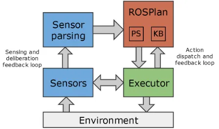
[image:2.612.326.550.165.297.2]The ROSPLAN framework is intended to run with any PDDL 2.1 (Fox and Long 2003) domain and planner, and to automate the planning process in ROS, coordinating the ac-tivities of lower level controllers. An overview of the ROS-PLANframework is shown in figure 1.
Figure 1: General overview of the ROSPLAN framework (red box), consisting of the Knowledge Base and Planning System ROS nodes. Sensor data is passed continuously to ROSPlan, used to construct planning problem instances and inform the dispatch of the plan (blue boxes). Actions are dispatched as ROS actions and executed by lower-level con-trollers (green box) which respond reactively to immediate events and provide feedback.
ROSPLANincludes two ROS nodes, the Knowledge Base and the Planning System. The Knowledge Base is simply a collection of interfaces, and is intended to collate the up-to-date model of the environment. The Planning System acts as a wrapper for the planner, and also dispatches the plan. The Planning System:
• builds the initial state automatically – as a PDDL problem instance – from the knowledge stored in the Knowledge Base;
• passes the PDDL problem instance to the planner and post-processes, then validates the plan; and
• dispatches each action, deciding when to reformulate and re-plan.
The architecture can be described in three parts: knowl-edge gathering,planning, anddispatch.
Knowledge gathering refers to the process of populating the Knowledge Base, generally from sensor data, parsed to correspond to the domain (such as waypoints generated from a geometric map) and as real information used to di-rect the low-level planners (such as the real coordinates of those waypoints). The Knowledge Base is then used in three ways by the Planning System:
2
• to generate the PDDL problem file;
• when translating PDDL actions to ROS action messages, to populate the messages with real data; and
• to notify the planner if there is a change in the environ-ment that may invalidate the plan.
[image:3.612.320.557.52.253.2]The first is described as a part of planning, the rest as part of dispatch. The architectural overview is shown in figure 2, using an example instantiation of the Knowledge Base de-scribed further in Section 3.
Figure 2: Architectural overview of the ROSPLAN frame-work. Blue boxes are ROS nodes. An example instantia-tion of the Knowledge Base is illustrated. Sensor data is interpreted for addition to the ontology, and actions are dis-patched as ROS actions from the Planning System. The Planning System (PS) and Knowledge Base (KB) communi-cate during construction of the intial state and plan dispatch. During dispatch the PS will update the KB with the plan-ning filter, and the KB may notify the PS of changes to the environment.
Knowledge Gathering
To use the ROSPLANframework a user must first instan-tiate the Knowledge Base. In figure 2 this is shown as an ontology. The ontology is then used to implement the ROS interface used by the Planning System. This ontology imple-mentation of the Knowledge Base is described in Section 3. The Knowledge Base is modular, to exploit the structural similarities between many robotics planning domains. For example, in our case study we represent the areas the AUV can move between as waypoints. For this reason the Knowl-edge Base and domain contain waypoints, and this transla-tion is handled by a generic component.
The Knowledge Base is updated as soon as new informa-tion becomes available. Each change to the Knowledge Base is checked against a planning filter supplied by the Planning System. If the filter contains the object, or object type, that has been added or removed, a notification message is sent to the Planning System. This alerts the Planning System that something has changed in the environment that could poten-tially invalidate the plan. The construction of the filter is handled by the Planning System, and described below.
1: procedurePLAN DISPATCH(DomainD, MissionM) 2: whileM contains goalsdo
3: I:=generateP roblem(D, M); 4: P :=plan(D, I);
5: F :=constructF ilter(D, I, P); 6: whileexecutedo
7: a:=pop(P); 8: dispatch(a);
9: whileactionExecutingdo 10: iff ilterV iolatedthen
11: execute:=⊥;
12: cancel(a);
13: end if
14: end while
15: execute:=execute∧actionSuccess(a); 16: end while
[image:3.612.61.281.170.332.2]17: end while 18: end procedure
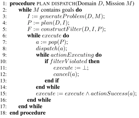
Figure 3: Detail of the plan, re-plan and dispatch loop used in ROSPLAN. generateP roblem(D, M) automati-cally generates a PDDL problem instance from the model.
constructF ilter(D, I, P) extracts the filter, used by the Knowledge Base. These procedures are explained fully in the text.
The Knowledge Base interface is used by the Planning System to generate the PDDL problem instance by supply-ing an initial state and goals. This is done through an inter-face comprised of ROS services.
Planning and Dispatch
The Planning System constructs a PDDL problem instance, sends this to an external PDDL planner, extracts a filter from the plan, dispatches the actions, and handles re-planning. This is illustrated in figure 3.
To generate the PDDL problem (line 3 of figure 3), the Planning System parses the supplied domain file, then queries the Knowledge Base for the object instances, facts, and fluents that comprise the initial state, and also the cur-rent goals. This problem file is then handed to a PDDL plan-ner (line4), which produces a plan. ROSPLANcan be used with any planner, so long as it can handle the syntactic re-quirements of the domain. In our case study we use an any-time version of POPF, a temporal and numeric planner. The amount of time allowed for planning is provided as a pa-rameter to the node. Once the plan has been found it can be validated using the Plan Validation Tool (VAL) (Howey, Long, and Fox 2004), which is included in ROSPLAN.
the ground fact(connected ?from ?to)are included in the filter. If these objects are removed, or altered in the Knowledge Base, a notification will be sent to the Planning System, as described above.
( : d u r a t i v e−a c t i o n d o h o v e r f a s t : p a r a m e t e r s ( ? v − v e h i c l e
? f r o m ? t o − w a y p o i n t ) : d u r a t i o n ( = ? d u r a t i o n
(\ ( d i s t a n c e ? f r o m ? t o ) ( v e l ? v ) ) ) : c o n d i t i o n ( and
( a t s t a r t ( a t ? v ? f r o m ) )
( a t s t a r t ( c o n n e c t e d ? f r o m ? t o ) ) ) : e f f e c t ( and
( a t s t a r t ( n o t ( a t ? v ? f r o m ) ) ) ( a t end ( n e a r ? v ? t o ) ) )
)
Figure 4: Thedo hover fast action for the inspection and valve turning task.
The action is dispatched by linking the PDDL action to a ROS action message (lines7−8). The relationship be-tween the high-level PDDL actions and low-level control has been investigated in many ways (Srivastava et al. 2014; Gaschler et al. 2013; Geib et al. 2006; McGann et al. 2008; Kortenkamp and Simmons 2008). To take advantage of pre-existing work, the translation layer can be instantiated as a separate node. The Planning System will dispatch PDDL actions – using a message type defined by ROSPLAN– to the intermediate layer, where the translation can be carried out. As well as this, ROSPLANincludes several modules, similar to those provided by the Knowledge Base, that cor-respond to common actions found in robotics domains. For example, the mapping from movement actions (analogous to the waypoint example in the Knowledge Base) to the move-baselibrary in ROS.
In ROSPLAN, re-planning is based on reformulation of the problem. There are three reasons that the system may re-plan:
1. the current action returns failure;
2. the Knowledge Base informs the planner of a change that invalidates the plan, or of new information important to the mission;
3. the current action, or plan, has gone significantly over or under budget (such as time or energy).
In the case of (1), the dispatch loop is broken (line 15), the problem instance is rebuilt from the current model of the environment, and a new plan is generated. In the case of (2) or (3), the current action may still be executing. In these cases the original plan is re-validated and then, if found to be invalid, the current action is cancelled and the dispatch loop broken as before (lines10−13).
3
Planning with
ROSP
LANIn this section we discuss implementing a ROS system with ROSPLAN. In particular we consider the scenario of plan-ning inspection and valve-turplan-ning missions for autonomous
underwater vehicles (AUVs). This scenario is fully de-scribed in section 4. To build a plan-based control archi-tecture with ROSPLANthe user must supply:
1. ROS action messages,
2. components to interpret the sensor data, 3. a PDDL domain file, and
4. an instantiation of the Knowledge Base.
As mentioned in sections 1 and 2, ROS libraries already ex-ist for (1), (2) and (4), and they need only to be linked to ROSPlan. The contribution of ROSPLANis an open, stan-dard framework to link these existing components together, and to automate the planning and dispatch process.
With respect to our case study, we describe our instanti-ation of the Knowledge Base; then the construction of the PDDL problem instance and integration with the planner; finally, we discuss plan dispatch.
Instantiating the Knowledge Base
The Knowledge Base was implemented in our case study to include an ontology, using the Web Ontology Language (OWL) (Hitzler et al. 2009). Anontologyis a way to repre-sent knowledge that can be expressed by description logics. Tenorth et al. (2010) combines semantic knowledge with spatial data to form asemantic mapof the environment, at-taching semantic information to a spatial map using an on-tology in a ROS framework for indoor household tasks. We used a similar approach in instantiating the Knowledge Base for our case study.
The interface to the ontology was adpated to the Knowl-edge Base interface and is used by ROSPLANto construct the initial state of the problem. Then, the ontology interface was augmented to check information against the planning filter when the information is added or removed.
The onotolgy is used to store symbolic representation of the environment. This includes: locations that the AUV can visit, inspection points the AUV is intended to observe, the valve panels, and the valves. The objects, and the relation-ships between them are derived from sensor data throughout the execution of a plan and collated in the ontology.
The possible trajectories the AUV can traverse are deter-mined by a set ofwaypoints. As mentioned in section 2, we use a generic component to handle the description and con-struction of waypoints. These waypoints are created using a probabilistic road map (PRM) (Kavraki, P. Svestka, and Overmars 1996), and stored in the ontology. We use an oc-tomap to check if a waypoint collides with an obstacle in the world. Similarly we use the octomap to determine whether the AUV can traverse between two waypoints. The octomap is built from sensor data and continuously updated. If an edge or waypoint is discovered to be colliding with the en-vironment, then it is removed from the ontology.
We use another component to describe valve panels and valves. This component simply listens to the feature match-ing process described in section 4 and adds discovered ob-jects to the ontology.
waypoints– these waypoints are stored in the ontology to provide a denser collection of waypoints around points of interest (in our case the possible locations of valve panels and unexplored space).
PDDL domain and problem instance
The domain for the valve turning mission is partially shown in figure 5. Thedo hover controlledanddo hover fast ac-tions are used to move an AUV between connected way-points. After usingdo hover fastthe position of the AUV must be corrected. There are two modes of movement used by the vehicle: one for thecorrect positionaction and con-trolled movement, another for fast movement.
The inspection points can be observed from possibly many waypoints, with varying amounts of visibility. Ob-serving an inspection point from a waypoint increases the(observed ?ip)function by the visibility amount,
(obs ?ip ?wp). An inpsection point ip is fully ob-served when(observed ip)>= 1.
The valves must be corrected before some deadline, spec-ified by a timed-initial-literal (Hoffmann and Edelkamp 2005). At the deadline the valve becomes blocked and cannot be turned. Before the deadline, the turn valve ac-tion can be used to change(valve state ?v)to equal
(valve goal ?v). After turning the valve, the AUV’s position must be corrected, and the panel re-examined.
When reformulating the problem for (re-)planning the Planning System queries the Knowledge Base for instances of all object types and their attributes, the problem instance is automatically generated and passed to the planner. An ex-ample problem instance from our case study is shown in fig-ure 6. In this problem there are five mission goals on a single valve. The time windows are known a priori and stored in the ontology as with the information derived from sensors.
Plan Dispatch
Plans are produced by POPF, a temporal metric planner widely used in the AI Planning community, which can cope with a wide variety of common features (Piacentini et al. 2013; Fox, Long, and Magazzeni 2012).
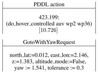
As described in Section 2, each PDDL action is linked to a ROS action message and dispatched. This translation is performed by separate components, corresponding to those used in the Knowledge Base. For example, figure 7 shows the translation of a PDDL action (do hover controlled) to a GotoWithYawRequestROS message from the COLA2 con-trol architecture for AUVs (Palomeras et al. 2012). This translation is performed by a component paired with the PRM generation. This component performs the translation of eachdo hover fastaction by first fetching the real coor-dinates from the Knowledge Base.
The plans are dispatched by sending the ROS actions to the lower-level controllers. The dispatcher is agnostic to the choice of lower level controller, allowing us to run ROS-PLANin both simulation and physical trials with no changes.
4
Case study
We demonstrate our approach with a case study planning in-spection and valve-turning missions for autonomous
under-( d e f i n e under-( domain v a l v e t u r n i n g ) . . .
( : t y p e s
w a y p o i n t i n s p e c t i o n p o i n t v e h i c l e p a n e l v a l v e ) ( : p r e d i c a t e s
( a t ? v − v e h i c l e ?wp − w a y p o i n t ) ( n e a r ? v − v e h i c l e ?wp − w a y p o i n t ) ( c o n n e c t e d ? wp1 ? wp2 − w a y p o i n t ) ( c a n s e e ? v−v e h i c l e
? i p−i n s p e c t i o n p o i n t ?wp−w a y p o i n t ) ( c a n e x a m i n e ? v − v e h i c l e
? p − p a n e l ?wp − w a y p o i n t ) ( c a n r e a c h ? v−v e h i c l e
? p−p a n e l ?wp−w a y p o i n t ) ( e x a m i n e d ? p − p a n e l ) ( on ? a − v a l v e ? p − p a n e l ) ( v a l v e b l o c k e d ? a − v a l v e ) ( v a l v e f r e e ? a − v a l v e ) )
( : f u n c t i o n s
( d i s t a n c e ? f r o m ? t o − w a y p o i n t ) ( o b s e r v e d ? i p − i n s p e c t i o n p o i n t ) ( o b s ? i p − i n s p e c t i o n p o i n t
?wp − w a y p o i n t ) ( v a l v e g o a l ? va − v a l v e ) ( v a l v e s t a t e ? va − v a l v e )
( v a l v e g o a l c o m p l e t e d ? va − v a l v e ) )
( : a c t i o n d o h o v e r c o n t r o l l e d . . . ) ( : a c t i o n d o h o v e r f a s t . . . ) ( : a c t i o n c o r r e c t p o s i t i o n . . . )
( : a c t i o n o b s e r v e i n s p e c t i o n p o i n t . . . ) ( : a c t i o n e x a m i n e p a n e l . . . )
( : a c t i o n t u r n v a l v e . . . ) )
Figure 5: Fragment of the domain for the inspection and valve turning task.
water vehicles (AUVs). The scenario was run in a simulation environment (UWSim) and in physical trials. The scenario involved a single AUV performing a valve turning mission.
The mission seeks to achieve persistent autonomy, with the key goal to show significantly reduced frequency of as-sistance requests during subsea inspection and intervention. This requires a strategic capability on the part of the vehi-cles, which can be achieved by planning over long-horizon activities, selecting sequences of actions that will achieve long-term objectives. Ensuring that the planning model re-mains robust requires careful matching of the model to the real world, including dynamically updating the model from continuous sensing actions.
The AUV was told to correct the positions of four valves, without prior knowledge of the size of the tank, existing ob-stacles, or location of the valve panel. The valve panel was placed nearby one of eight locations in an otherwise empty tank (as shown in Figure 8).
( d e f i n e ( p r o b l e m v a l v e t a s k ) ( : domain v a l v e t u r n i n g ) ( : o b j e c t s
auv − v e h i c l e
wp1 . . . wp20 − w a y p o i n t p1 − p a n e l
v1 − v a l v e ) ( : i n i t
( a t auv wp1 )
( c a n r e a c h auv wp8 p1 )
( on v1 p1 ) ( v a l v e b l o c k e d v1 ) ( = ( v a l v e g o a l v1 ) 0 )
( = ( v a l v e s t a t e v1 ) 0 )
( = ( v a l v e g o a l c o m p l e t e d v1 ) 0 )
; ; VALVE TIME WINDOW
( a t 1 ( n o t ( v a l v e b l o c k e d v1 ) ) ) ( a t 1 ( v a l v e f r e e v1 ) )
( a t 1 ( = ( v a l v e g o a l v1 ) 1 4 4 ) ) ( a t 251 ( v a l v e b l o c k e d v1 ) ) ( a t 251 ( n o t ( v a l v e f r e e v1 ) ) )
. . .
( c o n n e c t e d wp1 wp2 )
( = ( d i s t a n c e wp1 wp2 ) 5 . 0 7 2 ) ( c o n n e c t e d wp2 wp1 )
( = ( d i s t a n c e wp2 wp1 ) 5 . 0 7 2 ) . . . )
( : g o a l ( and
[image:6.612.381.498.61.168.2](>= ( v a l v e g o a l c o m p l e t e d v1 ) 5 ) ) ) )
Figure 6: Fragment of the problem instance for the inspec-tion and valve turning tasks.
PDDL action
423.199:
(do hover controlled auv wp2 wp36) [10.726]
GotoWithYawRequest
north lat:=0.012, east lon:=2.146, z:=1.383, altitude mode:=False,
yaw := 1.541, tolerance := 0.3
Figure 7: An example conversion from the PDDL action do hover controlledto aGotoWithYawRequestaction. The real values are extracted from the Knowledge Base by the action dispatcher before the action is sent to the movement controller.
panel has been located, the remaining inspection actions will be discarded and the AUV will move to the panel and closely inspect the valves. Finally, having detected the current an-gles of the valves, the AUV will use its gripper to correct the positions of any misaligned valves.
We aim to show from this study that the ROSPLAN
framework:
[image:6.612.51.279.62.351.2]1. through task planning queries, generates a reasonable plan to achieve the mission goals;
Figure 8: Scenario for the valve turning task. The possible locations of the valve panel are shown by the dark circles on opposite sides of the tank. The tank is roughly 5m wide, with 8m between opposing panel locations.
2. is able to adapt to unexpected discoveries or changes in the environment, in a way that is more intelligent than simple reactive behaviour; and
3. is robust to inaccuracy of the sensors and low-level con-trollers and other uncertaintry in the real world.
The problem itself is simple in task planning terms. How-ever, as the ROSPLANframework is general with respect to choice of domain and planner, here we focus on the chal-lenges encountered at the meta-level; in dynamically con-structing the problem and dispatching the plan. The valve turning mission involves:
1. a series of planned and uninterrupted dispatched actions (searching for the valve panel),
2. the discovery of new information, interrupting the execu-tion of a plan (the discovery of a valve panel),
3. action failure (the temperamental turning of valves under-water) and sensor inaccuracies (in the detected position of the panel, and angles of the valves).
Thus, the valve turning mission is a suitable example for our three aims.
Girona 500 I-AUV
The Girona 500 I-AUV (Ribas et al. 2012) is a compact and lightweight AUV with hovering capabilities, shown in fig-ure 9. The vehicle can be actuated insurge,sway,heaveand
yaw(ψ), while it is stable inroll(Φ) andpitch(θ). The pay-load area is equipped with an ECA CSIP manipulator which is an under-actuated manipulator with 4 degrees of freedom (DoF). This manipulator can control the Cartesian position (x,y,z) and theroll(Φ) of the end-effector. However, be-cause it is under-actuated,pitchandyaware defined by the Cartesian position.
[image:6.612.89.259.395.521.2]Figure 9: Girona 500 AUV in the water tank, equipped with the manipulator and a customised end-effector. In the back-ground there is a mock-up of a valve panel.
Action Implementation
The Girona 500 AUV uses a simultaneous localisation and mapping algorithm (SLAM), based on an EKF filter, to acheive a robust vehicle localisation. The EKF-SLAM com-bines the information of different navigation sensors (i.e. an AHRS, a DLV and a depth sensor) with a motion model to obtain an estimation of the vehicle position. It also uses de-tected landmarks in the environment to improve the AUV position, and maintain a map of their location. In our imple-mentation, the valve panel (see figure 10) is a landmark. To identify the panel, a vision algorithm analyses the images gathered by the AUV’s main camera and compares them with a template image of the panel. Then, when a suffi-cient number of features are matched across both images, the presence of the panel is identified, and its position/orien-tation accurately estimated. This process is embodied in the actionobserve inspection point.
Once the position of the panel is known, it is possible to estimate the valves’ orientations, which corresponds to the examine panelaction. The action extracts a region of inter-est around the expected valve position and applies a Hough transform to estimate the main line orientation.
The Girona 500 can be controlled by means of body force and velocity requests, and waypoints requests. A cascade control scheme is used to link these controllers: the pose controller generates the desired velocity as output, which is the input for the velocity controller. This in turn generates the force and torque that are fed to the force controller to finally obtain the required setpoints for each thruster.
Two motion modes have been implemented to guide the vehicle. The first (do hover controlledandcorrect position) follows the cascade scheme moving the AUV holonomi-cally. However, if the waypoint is far from the vehicle’s current position this motion mode becomes too slow. Then, a variation of the line-of-sight pure pursuit algorithm de-scribed by Fossen (Fossen 2011) is used (do hover fast).
To perform the valve turning action (turn valve) we have implemented a learning by demonstration algorithm (LbD). LbD is a machine learning technique designed to transfer the
knowledge from an expert to a machine through an abstrac-tion process that generalises a task from a set of operator demonstrations. Here we address a particular case study, tar-geting valve turning. However, the implementation through a LbD algorithm can be easily adapted to other manipulation actions, and is ideal for facing new tasks.
The LbD algorithm used in this action is an extension of dynamic movement primitives (DMP). DMP is a technique where the learned skill is encapsulated in a superposition of basis motion fields. Unlike other methods, DMP dynami-cally generates the required commands to perform the re-production of the task trajectory. This makes the approach more robust to external perturbations.
In our particular implementation, the extended version of the DMP (Carrera et al. 2014) learns a trajectory of 8 DoF to represent the position (x,y, z) and orientation (yaw) of the AUV and the position (x,y,z) and alignment (roll) of the end-effector. Because this trajectory is recorded with respect to a valve center, the model learned for changing the reference valve is good enough for grasping any other valve. The roll motion performed to turn the valve is not included in the learning algorithm. Instead, a simple controller executes the turn for any rotation angle once the valve is grasped.
Figure 10: Camera image of the valve panel, taken from the AUV’s end-effector.
Outcome
The physical trials were successful, with the AUV correcting all the valves. Replanning was performed for two reasons: intially discovering the panel, and when aturn valveaction failed. Theturn valveaction did not have a perfect success rate, as sometimes the valve would be missed by the gripper, or knocked when the AUV retreated from the panel.
[image:7.612.335.540.322.473.2]PDDL action ROS action message 0.000: (observe inspection point auv wp1 ip3) [10.000]
-10.001: (correct position auv wp1) [10.000] GotoWithYawRequest 20.002: (do hover fast auv wp1 wp2) [35.848] GotoWithYawRequest 55.851: (correct position auv wp2) [10.000] GotoWithYawRequest 65.852: (observe inspection point auv wp2 ip4) [10.000]
-75.853: (correct position auv wp2) [10.000] GotoWithYawRequest 85.854: (do hover controlled auv wp2 wp23) [16.710] GotoWithYawRequest
... ...
423.199: (do hover fast auv wp2 wp36) [10.726] GotoWithYawRequest 433.926: (correct position auv wp36) [10.000] GotoWithYawRequest 443.927: (observe inspection point auv wp36 ip9) [10.000]
-0.000: (turn valve auv wp1 p0 v1) [100.000] valve turning action 100.001: (correct position auv wp1) [10.000] GotoWithYawRequest 110.002: (turn valve auv wp1 p0 v3) [100.000] valve turning action 210.003: (correct position auv wp1) [10.000] GotoWithYawRequest 220.004: (turn valve auv wp1 p1 v2) [100.000] valve turning action
... ...
[image:8.612.144.467.50.260.2]1310.002: (correct position auv wp1) [10.000] GotoWithYawRequest 1311.003: (turn valve auv wp1 02 v4) [100.000] valve turning action
Figure 11: Fragments of two PDDL plans produced during the valve turning mission. The first plan fragment shows the beginning and end of an inspection mission, searching for the valve panel. The second fragment shows the plan to correct the valves, once the panel has been found.
new problem instance, which included the newly discovered panel, and then passed this to the planner.
In the second case – when aturn valveaction failed – the action itself did not return failure, as the learned action does not self-validate. Instead, the action incorporated an exam-ination of the panel following the attempted turn. This ex-amination updated the angle of the valve in the Knowledge Base. If theturn valveaction failed, then the planning filter would be violated and a replan would take place. The new plan would repeat the attempt to correct the valve.
Figure 11 shows fragments of the plans generated during the valve turning mission. The table shows the PDDL ac-tions and their corresponding ROS action messages. The observe PDDL action does not have a corresponding ROS action, as the visual sensing is continuous and passive. The observe action merely causes the AUV to wait for several seconds after orienting itself towards the inspection point – this aids the visual detection. The two movement types, fast (do hover fast) and controlled (do hover controlledand correct position), have the same action type: GotoWith-YawRequest. This ROS action message is shown in more detail in figure 7. These messages are sent to different action servers depending upon the movement type, as described above. Finally, thevalve turning actionmessage is sent to the LbD controller described above.
In the physical trials the inspection points did not line up with the borders of the tank, nor with the actual location of the valve panel. This was due to safety concerns; it is better to keep the AUV further from the walls, as any drift in the accuracy of its current estimated position could cause it to collide. This proved to highlight a strength of the approach. As the PDDL problem and its underlying PRM are generated dynamically from the sensor data, once the valve panel was discovered the waypoints of the new PRM would be reposi-tioned to allow the AUV access to the valve panel – closer
than the safety constraints would have allowed. Simultane-ously, the real position of the panel would be known, and used as a landmark to help keep the AUV’s estimated posi-tion accurate, removing the need for the safety net.
5
Conclusion
References
Beetz, M., and McDermott, D. 1994. Improving Robot Plans Dur-ing Their Execution. InProc. International Conference on AI Plan-ning Systems (AIPS).
Bernardini, S.; Fox, M.; and Long, D. 2014. Planning the Be-haviour of Low-Cost Quadcopters for Surveillance Missions. In Proc. Int. Conf. on Automated Planning and Scheduling (ICAPS). Carrera, A.; Palomeras, N.; Ribas, D.; Kormushev, P.; and Car-reras, M. 2014. An intervention-auv learns how to perform an underwater valve turning. InOCEANS - Taipei, 2013 MTS/IEEE. Cashmore, M.; Fox, M.; Larkworthy, T.; Long, D.; and Magazzeni, D. 2014. AUV Mission Control Via Temporal Planning. InProc. Int. Conf. on Robots and Automation (ICRA).
Coles, A.; Coles, A.; Fox, M.; and Long, D. 2010. Forward-Chaining Partial-Order Planning. InProc. Int. Conf. on Automated Planning and Scheduling (ICAPS), 42–49.
Della Penna, G.; Magazzeni, D.; and Mercorio, F. 2012. A univer-sal planning system for hybrid domains.Applic. Intell.36(4):932– 959.
Dornhege, C.; Hertle, A.; and Nebel, B. 2013. Lazy Evaluation and Subsumption Caching for Search-Based Integrated Task and Motion Planning. InProc. IROS workshop on AI-based robotics. Eyerich, P.; Mattm¨uller, R.; and R¨oger, G. 2012. Using the context-enhanced additive heuristic for temporal and numeric planning. In Towards Service Robots for Everyday Environments. 49–64. Firby, R. J. 1987. An investigation into reactive planning in com-plex domains. InProc. National conference on Artificial intelli-gence (AAAI), 202–206.
Fossen, T. I. 2011. Handbook of marine craft hydrodynamics and motion control. John Wiley & Sons, Ltd.
Fox, M., and Long, D. 2003. PDDL2.1: An Extension to PDDL for Expressing Temporal Planning Domains. Journal of AI Research (JAIR)20:61–124.
Fox, M.; Long, D.; and Magazzeni, D. 2012. Plan-based policies for efficient multiple battery load management.J. Artif. Intell. Res. (JAIR)44:335–382.
Frank, J., and Jonsson, A. 2003. Constraint-based attribute and interval planning.Journal of Constraints8(4).
Gaschler, A.; Petrick, R. P. A.; Giuliani, M.; Rickert, M.; and Knoll, A. 2013. KVP: A knowledge of volumes approach to robot task planning. InProc. Int. Conf. on Intelligent Robots and Systems (IROS), 202–208.
Geib, C.; Mour˜ao, K.; Petrick, R.; Pugeault, N.; Steedman, M.; Krueger, N.; and W¨org¨otter, F. 2006. Object Action Complexes as an Interface for Planning and Robot Control. InProc. Humanoids-06 Workshop: Towards Cognitive Humanoid Robots.
Gerevini, A., and Serina, I. 2002. LPG: A planner based on lo-cal search for planning graphs. InProc. Int. Conf. on Automated Planning and Scheduling (AIPS). AAAI Press.
Ghallab, M.; Nau, D.; and Traverso, P. 2004.Automated Planning: Theory and Practice. Morgan Kaufmann.
Graham, R.; Py, F.; Das, J.; Lucas, D.; Maughan, T.; and Rajan, K. 2012. Exploring Space-Time Tradeoffs in Autonomous Sampling for Marine Robotics. InProc. Int. Symp. Experimental Robotics. Hitzler, P.; Kr¨otzsch, M.; Parsia, B.; Patel-Schneider, P. F.; and Rudolph, S., eds. 2009.OWL 2 Web Ontology Language: Primer. W3C Recommendation. Available at http://www.w3.org/TR/owl2-primer/(Nov 2014).
Hoffmann, J., and Edelkamp, S. 2005. The Deterministic Part of IPC-4: An Overview.Journal of AI Research (JAIR)24:519–579.
Howey, R.; Long, D.; and Fox, M. 2004. VAL: Automatic Plan Validation, Continuous Effects and Mixed Initiative Planning Us-ing PDDL. InProc. Int. Conf. on Tools with AI (ICTAI), 294–301. Ingrand, F.; Chatilla, R.; Alami, R.; and Robert, F. 1996. PRS: a high level supervision and control language for autonomous mobile robots. InIEEE Int.l Conf. on Robotics and Automation.
Kavraki, L. E.; P. Svestka, J.-C. L.; and Overmars, M. H. 1996. Probabilistic roadmaps for path planning in high-dimensional con-figuration spaces. InIEEE Trans. on Robotics and Automation. Kortenkamp, D., and Simmons, R. G. 2008. Robotic Systems Ar-chitectures and Programming. InSpringer Handbook of Robotics. Springer. 187–206.
Lemai-Chenevier, S., and Ingrand, F. 2004. Interleaving Temporal Planning and Execution in Robotics Domains. InProceedings of the National Conference on Artificial Intelligence (AAAI). Magazzeni, D.; Py, F.; Fox, M.; Long, D.; and Rajan, K. 2014. Pol-icy learning for autonomous feature tracking. Autonomous Robots 37(1):47–69.
McGann, C.; Py, F.; Rajan, K.; Thomas, H.; Henthorn, R.; and McEwen, R. S. 2008. A deliberative architecture for AUV control. InProc. Int. Conf. on Robotics and Automation (ICRA).
Muscettola, N.; Dorais, G.; Fry, C.; Levinson, R.; and Plaunt, C. 2002. IDEA: Planning at the Core of Autonomous Reac-tive Agents. InProc. of AIPS Workshop on On-line Planning and Scheduling.
Palomeras, N.; El-Fakdi, A.; Carreras, M.; and Ridao, P. 2012. COLA2: A Control Architecture for AUVs. IEEE Journal of Oceanic Engineering37(4):695–716.
Piacentini, C.; Alimisis, V.; Fox, M.; and Long, D. 2013. Com-bining a Temporal Planner with an External Solver for the Power Balancing Problem in an Electricity Network. InProc. Int. Conf. on Automated Planning and Scheduling (ICAPS).
Ponzoni, C.; Chanel, C.; Lesire, C.; and Teichteil-Knigsbuch, F. 2014. A Robotic Execution Framework for Online Probabilis-tic (Re)Planning. InProc. Int. Conf. on Automated Planning and Scheduling (ICAPS).
Py, F.; Rajan, K.; and McGann, C. 2010. A systematic agent framework for situated autonomous systems. InProc. of Int. Conf. on Autonomous Agents and Multi-Agent Systems (AAMAS). Quigley, M.; Conley, K.; Gerkey, B.; Faust, J.; Foote, T.; Leibs, J.; Wheeler, R.; and Ng, A. Y. 2009. ROS: an open-source Robot Operating System. InICRA workshop on open source software, volume 3.
Ribas, D.; Palomeras, N.; Ridao, P.; Carreras, M.; and Mallios, A. 2012. Girona 500 AUV: From Survey to Intervention. Mechatron-ics, IEEE/ASME Transactions on17(1):46–53.
Simmons, R. 1992. Concurrent planning and execution for au-tonomous robots.IEEE Control Systems12(1):46–50.
Srivastava, S.; Fang, E.; Riano, L.; Chitnis, R.; Russell, S.; and Abbeel., P. 2014. Combined Task and Motion Planning through an Extensible Planner-Independent Interface Layer. InProc. Int. Conf. on Robotics and Automation (ICRA).
Tenorth, M., and Beetz, M. 2009. KnowRob – Knowledge Process-ing for Autonomous Personal Robots. InIEEE/RSJ International Conference on Intelligent Robots and Systems, 4261–4266. Tenorth, M.; Bartels, G.; and Beetz, M. 2014. Knowledge-based Specification of Robot Motions. InProc. European Conf. on AI (ECAI).