DESIGN AND BUILD A NEW COLD PRESS MINI MACHINE CONTROL BY PLC (PROGRAMMABLE LOGIC CONTROL)
NOORIZRAQ BIN MOHD Y ASIN
This Report Is Submitted In Partial Fulfillment Of Requirements For The Bachelor Degree of Electronic Engineering (Industrial Electronic)
Fakulti Kejuruteraan Elektronik dan Kejuruteraan Komputer Universiti Tek:nikal Malaysia Melaka
May 2007
Tajuk Projek Sesi
Pengajian
Say a
UNIVERSTI TEKNIKAL MALAYSIA MELAKA
F AKUL TI KEJURUTERAAN ELEKTRONIK DAN KEJURUTERAAN KOMPUTER BORANG PENGESAHAN STATIJS LAPORAN
PROJEK SARJANA MUDA ll
Design and build a new cold press machine control by PLC . . . . 2006/2007 ... .
NOORIZRAO BIN MOHO YASIN
(HURUF BESAR)
mengaku membenarkan Laporan Projek Sarjana Muda ini disimpan di Perpustakaan dengan syarat-syarat kegunaan seperti berikut:
1. Laporan adalah hakmilik Universiti Teknikal Malaysia Melaka.
2. Perpustakaan dibenarkan membuat salinan untuk tujuan pengajian sahaja.
3. Perpustakaan dibenarkan membuat salinan laporan ini sebagai bahan pertukaran antara institusi pengajian tinggi.
4. Sila tandakan ( ...J ) :
D
TERHAD"0
TIDAKTEIUIAD(Mengandungi maidumat yang berdarjah k:eselamatan atau
k:epentingan Malaysia seperti yang tennak:tub di dalam AKT A RAHSIA RASMI 1972)
(Mengandungi maklumat terbad yang telah ditentukan oleh organisasilbadan di mana penyelidikan dijalankan)
Disahkan oleh:
(f ANDATANGAN PENULIS)
Alamat Tetap: ... . LOT 436. JLN lU KAST ARI
81800 ULU TIRAM. JOHOR BHARU
· .. t..--rlo~lo1
"I hereby declare that the report is the result of my own, as clearly stated in the sources of references and sources is explained and stated."
Signature: ...
~
... .Name: Noorizraq Bin Mohd Y asin Date: ....
?.
"1 ..
~~
:
..
!
.
..
?:9.
<?
X. .
.
.
.
SUPERVISOR APPROVEMENT
"II we have approve that I've read the Final Year Project report with my opinion this report is fulfill the scope and the quality to be honored with the Ijazah Smjana Muda
KejlU1lteraan Elektronik (Elektronik Industri)."
Signature: •..•...
?.:
~
...
.. .
Supervisors Name: En Zulhairi Bin Othman
Date: ...
?:?:./.
?
.
'!.
{
~.
?
.
.
.
.
...
.
.
.
..
....
..
..
... .
ZULHAIRI B OTHMAN .
l<~tua Jabalan (Eiektronik lndustrr) Fakulti Kej Elektc<l"W. dan K~i i':JfTl!lUter i>KEKK),
Universiti T9knikal Malays•• Mc:•aka \UreM).
Karung Ber1MlCI 1200.
Ayer Kerch, 75450 Melaka
I dedicate this to both of my parents, my family, friends and electronic engineering education.
v
ACKNOWLEDGEMENT
Firstly, I would like to thankful to Almighty for giving me strength to complete this report. More than that, I would like to thankful to En Zulhairi Bin Othman as my supervisor as long as I have pretend to finish this Final Year Project. He has helped me in many ways such as give an opinion, help to find out the solution and discussion to finish this project.
Moreover,
also
to theindividual
named En. Hj Mohammad Bin Abdullah, this lecturer in Giat MARA Institute, which gives the permission and cooperation to use their workshop and mechanical equipment along the development of this project. His cooperation and help is a lot and I'm thanks for that. Furthermore, to Mrs Bulan BintiAbdull~ lecturer from UiTM Shah Alam for giving us to use and borrow the pneumatic
equipment likes valve and cylinder.
Not forget to my parent that has gives a supported to make sure this project would be finish smoothly. Also to my project partner Mohd Firdaus bin Hashim for his cooperation and helps along this project. Further, to all my friends have supported me and together estimated the problems in this project. Consequently, I would like to thanks all that have make sure this project is excellent. Hope God bless you are for your kindness. Amen ...
Vl
ABSTRACT
Mini cold press machine is a project to improve previous press machine which
have weakness in safety while operating it. This matter creates a lot of problem and at
the same time the operators and technician have the higher risk to have an accident in
industries.
The solution for this problem is a development of a new program of machine
which running same operation but the machine is more safety and easy to setup when
VII
ABSTRAK
Project mini cold press machine ini adalah suatu usaha untuk menaik tarafkan
mesin tekan yang sedia ada dimana pada mesin yang sedia ada, bahagian ciri-ciri
keselamatan kurang dititik beratkan. Jadi ia akan mengundang kepada risiko berlakunya
kemalangan ditempat kerja oleh operator dan juruteknik.
Penyelesaian untuk masalah ini ialah membuat program yang baru pada mesin
dimana mesin berfunsi seperti sedia ada teta.pi ia lebih selamat dan senang untuk
TABLE OF CONTENTS CONTENT PROJECT TITLE DECLARATION DEDICATION ACKNOWLEDGEMENT ABSTRACT ABSTRAK
TABLE OF CONTENTS
LIST OF FIGURE
CHAPTER I : INTRODUCTION
1.1 Project overview
1.1.1 Programmable Logic controller
1.1.2 History of Programmable Logic controller
1.1.3 The old way
1.1.4 Disadvantages of the old way
1.1.5 The first programmable controllers
1.2 Objectives of project
1.3 Scope of Project
1.4 Problem Statement
1.5 Project Methodology
IX
CHAPTER 2 : LITERATURE REVIEW
2.1 Overview ofPC-Based control 14
2.2 Advantages of Computer for industry controller. 16
2.3 PLC Advantages and Disadvantages 17
2.4 Industrial sensor 18
2.5 Electronic Field Sensor 19
2.5.1 Magnetic sensor 20
2.5.1.1 Photoelectric Sensor Construction 21
2.5.1.2 Basic Components 22
2.5.1.3 Photoelectric Sensors of Operation 24
2.5.1.4 DC out Of Photoelectric 24
2.5.1.5 Type of output and load connections 24
2.6 Limit Switch 26
2.7 Actuator (Relay) 27
2.7.1 Relay 27
2. 7 .1.1 Pole and Throw 29
2. 7 .1.2 Application of Relay 30
2.7.1.3 Operation ofRelay 30
2.7.1.4 The Latching Relay Circuit 31
2. 7 .1.5 Advantages of Relays 33
2.7.2 DC Motor 33
CHAPTER
3 :
PROGRAM DEVELOPMENT3.1 INTRODUCTION 35
3.2 Ladder Logic 38
3.3 Ladder Diagram 38
3.3.1 Ladder Diagram Program for Sorting Device 39
CHAPTER 4 : INTERFACING AND TROUBLESHOOTING
4.1 Introduction
4.2 Interfacing
4.2.1 Steps to develop the ladder diagram
in
FPWIN GR Programming
4.3 Troubleshooting
4.4 Check Input I Output Device
CHAPTER 5 : RESULT
5.1 Input I Output Assignment
5.2 Wiring Diagram
5.2.1 Wiring Diagram (Inputs)
5.2.2 Wiring Diagram (Inputs- Expansion)
5.3 Wiring Diagram (Outputs)
5.4 Ladder Diagram
5.5 Mnemonic Code
5.6 Cold Press Machine
5.7 Machine Operation (Flow Chart)
CHAPTER 6 : DISCUSSION AND CONCLUSION
6.1 Discussion
6.2 Conclusion
REFERENCES APPENDIX A APPENDIXB
APPENDIXC
APPENDIXD FIGURES 1.1 1.2 1.31.4
2.12.2
2.3
2.4
2.5
2.6
2.7
2.8
2.9 2.10 2.11 2.12 3.1 3.2 3.3 3.4 PROGRAM INSTRUCTIONS EXPANSION INSTRUCTION
NETWORK CABLE
INFORMATION SCUD-STATE AUTO SWITCHES
LIST OF FIGURES
TITLE
Example ofPLC ladder diagram.
Flowchart of project methodology
Solenoid valve
DC Motor
Photoelectric Sensor Components
LED (Light Emitting Diode) Construction
Photo Electric Sensor
NPN (Sinking) Field Device Example
PNP (Sourcing) Field Device Example
Roller leaf-low force large movement
Typical Enclosure Actuation
Relays
A relay providing isolation between two circuits
The mechanical operation of relay
The latching relay circuit
DC motor 12 V
A System Approach to Programmable Controller Design
Rung 1 of Ladder Diagram
Rung 2 of Ladder Diagram
Rung 3 of Ladder Diagram
X11
3.5 Rung 4 of Ladder Diagram 40
3.6 Rung 5 of Ladder Diagram 40
3.7 Rung 6 of Ladder Diagram 41
3.8 Rung 7 of Ladder Diagram 41
3.9 Rung 8 of Ladder Diagram 42
3.10 Rung 9 of Ladder Diagram 42
3.11 Rung 10 of Ladder Diagram 42
3.12 Rung 11 of Ladder Diagram 43
3.13 Rung 12 of Ladder Diagram 43
3.14 Rung 13 of Ladder Diagram 43
3.15 Rung 14 of Ladder Diagram 43
3.16 Rung 15 of Ladder Diagram 44
3.17 Rung 16 of Ladder Diagram 44
3.18 Rung 17 of Ladder Diagram 44
3.19 Rung 18 of Ladder Diagram 45
3.20 Rung 19 of Ladder Diagram 45
3.21 Rung 20 of Ladder Diagram 46
3.22 Rung 21 of Ladder Diagram 46
3.23 Rung 22 of Ladder Diagram 47
3.24 Rung 23 of Ladder Diagram 47
3.25 Rung 24 - Rung 26 of Ladder Diagram 48
3.26 Rung 27 and Rung 28 of Ladder Diagram 48
3.27 Rung 29 and Rung 30 of Ladder Diagram 48
3.28 Rung 31 and Rung 32 of Ladder Diagram 49
Xlll
3.30 Mnemonic code 50
4.1
Block diagram of the typical component that makes up a PLC52
4
.
2
Wiring configuration for sorting device with PLC53
4.3
FPWINGR54
4.4
Select PLC Type54
4.5
PLC workspace 554.6
PLC work online box 564.7
Download to PLC 561
CHAPTER I
INTRODUCTION
1.1 PROJECT OVERVIEW
lbis machine is use to attach stickers and place button to the radio panel. It is
controlled by PLC. It consist of
5
pneumatic cylinder, where each cylinder have theirown function which are to press the radio panel, carry the finished radio panel to the
pickup and place section and there the cylinder is used to grip and pick up the radio
panel.
lbis project is conducted to overcome the problem exist, emergency button not
function if user used machine in manual mode. In automatic mode, user can use just one
hand to handle the machine although have two switch at the machine and time machine
press the panel radio difficult to change at the current machine by enhancing the
machine, modify the program and added external timer. lbis is to produce a mini
2
1.1.1 PROGRAMMABLE LOGIC CONTROL (PLC)
Automation of many different processes, such as controlling machines or factory
assembly lines, is done through the use of small computers called a programmable logic
controller (PLC). This is actually a control device that consists of a programmable
microprocessor, and is programmed using a specialized computer language. Before, a
programmable logic controller would have been programmed in ladder logic, which is
similar to a schematic of relay logic. A modem programmable logic controller is usually
programmed in any one of several languages, ranging from ladder logic to Basic or C.
Typically, the program is written in a development environment on a personal computer
(PC), and then is downloaded onto the programmable logic controller directly through a
cable connection. The program is stored in the programmable logic controller in
non-volatile memory.
Programmable logic controllers contain a variable number of Input/Output (1/0)
ports, and are typically Reduced Instruction Set Computer (RISC) based. They are
designed for real-time use, and often must withstand harsh environments on the shop
floor. The programmable logic controller circuitry monitors the status of multiple sensor
inputs, which control output actuators, which may be things like motor starters, solenoids, lights and displays, or valves.
The programmable logic controller has made a significant contribution to factory
automation. Earlier automation systems
had
to use thousands of individual relays andcam timers, but all of the relays and timers within a factory system can often be replaced
with a single programmable logic controller. Today, programmable logic controllers
deliver a wide range of functionality, including basic relay control, motion control,
process control, and complex networking, as well as being used in Distributed Control
Systems.
Digital signals yield an on or off signal, which the programmable logic controller
3
controls. and these analog signals are seen by the programmable logic controller as
floating point values.
There are several different types of interfaces that are used when people need to
interact with the programmable logic controller to configure it or work with it. This may
take the form of simple lights or switches or text displays, or for more complex systems,
a computer of Web interface on a computer running a Supervisory Control and Data
Acquisition (SCADA) system. [I]
Programmable logic control or PLC is the most commonly used industrial
automation technique in the world. It is universally applied for factory automation.
process control and manufacturing systems.
Programmable logic control originated from the creation of computerized
versions of relay control systems used to control manufacturing and chemical process
systems. The programming is done using a special technique called ladder logic, which
allows sequences of logical actions to be set up, inter-linked and timed. A standard task
in logic control is batch control and sequencing in a process system.
A PLC or Programmable Logic Controller is a user friendly, microprocessor
specialized computer that carries out control functions of many types and levels of
complexity. Its purpose is to monitor crucial process parameters and adjust process
operations accordingly. It can be programmed, controlled and operated by a person
unskilled in operating computers. Essentially, a PLC's operator draws the lines and
devices of ladder diagrams with a keyboard onto a display screen. The resulting drawing
is converted into computer machine language and run as a user program.
PLC will operate any system that bas output devices that go on and off (Discrete,
or Digital, outputs).lt can also operate any system with variable (analog) outputs. The
Programmable Logic Control can be operated on the input side by ON/OFF devices or
4
1.1.2 IDSTORY OF PROGRAMMABLE LOGIC CONTROL (PLC)
The programmable logic controller may be the best example ever of taking an
existing technology and applying it to meet a need. In the 1960s and 1970s, industry was
beginning to see the need for automation. Industry saw the need to improve quality and
increase productivity. Flexibility had also become a major concern. Industry needed to
be able to change processes quickly to meet the needs of the consumer.
Programmable logic controllers were first created to serve the automobile
industry, and the first programmable logic controller project was developed in 1968 for
General Motors to replace hard-wired relay systems with an electronic controller.
1.1.3 THE OLD WAY
Imagine an automated manufacturing line in the 1960s and 1970s. There was
always a huge wiring panel to control the system. The wiring panel could cover an entire
wall. Inside the panel were masses of electromechanical relays. These relays were all
hardwired together to make the system work. Hardwiring means that an electrician had
to install wires between the connections of the relays. An engineer would design the
logic of the system and the electricians would be given a blueprint of the logic and
would have to wire the components together. There were hundreds of electromechanical
relays in a system before programmable logic controllers were developed.
The drawing that the electrician was given was called a ladder diagram. They
were called ladders because they resemble a ladder in appearance. The ladder showed all
the switches, sensors, motor, valve, relays, etc, that would be in the system. It was the
5
Rl4 X26 Rl8 Rl5
1 , K 30
[
Rls~'l
. _ _ l ___________..rT!X
Tl Rl5 X25 X28 R20
R16~ ~
!=f'~'
I
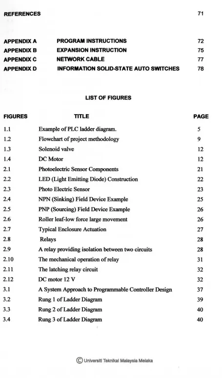
-Figure 1.1: Example ofPLC ladder diagram.
Note the similarity in appearance to a ladder. There are three rung in this
example. Power is represented by the left and right upright. There are five inputs and
two outputs in the example. Inputs are on the left, output at the right of each rung.
It is not hard to imagine that the engineer made a few small errors in his/her
design. It is also conceivable that the electrician may have made a few errors in wiring
the system. It is also not hard to imagine a few bad components. The only way to see if
everything was correct was to run the system. Systems are normally not perfect on the
first attempt.
Troubleshooting was done by running the actual system. This was a very
consuming process. The system had to be disabled for wiring changes. This means that
all of the production personnel associated with that production line was without work
until the system was repaired. After the electrician had completed the troubleshooting
[image:19.522.48.480.93.624.2]6
1.1.4 DISADVANTAGES OF THE CONVENTIONAL WAY
One of the problems with this type of control is that it is based on mechanical relays. Mechanical devices are usually the weakest link in systems. Mechanical devices have moving part that can wear out If one relay failed, the electrician might have to troubleshoot the whole system again. The system was down again until the problem was found and corrected.
Another problem with hardwired logic is that if a change must be made, the system must be shut down and the panel rewired. If a company decided to change the sequence of operations (even a minor change), it will be a major expense and loss of productions time while the system do not produce parts.
1.1.5 THE FIRST PROGRAMMABLE CONTROLLERS
General Motor saw the need for a replacement for hardwired control panels. Increased competition forced the automak.ers to improve manufacturing performance in
both quality and productivity. Flexibility, rapid changeover and reduced downtime
became very important.
GM realized that a computer could be used for logic instead of hardwired relays.
7
1.2 OBJECTIVES
The objective of this project is to identify the all of function the cold press
machine and the input/output equipment like sensor, switch, external timer and solenoid
valve.
Another objective is to study the component of Flexible Manufacturing System
(FMS) to conform to the model to be developed. The component of Flexible
Manufacturing System is pneumatic equipment (solenoid valve and pneumatic cylinder)
and control equipment (Programmable Logic Control). PLC is the most commonly used
industrial automation technique in the world. It is universally applied for factory
automation, process control and manufacturing systems.
To build a new Flexible Manufacturing System (FMS) model that will be cost,
time and quantity effectiveness is other objectives should be done. Machine need one
worker only to handling machine and send the set, not two workers like other machine.
In this case, we can cut cost for pay one worker. The last objective is for build low cost
8
1.2 SCOPE OF WORKS
The scopes of the project are:
1. Identify function of the electronics component like sensor and switch for control/handle pneumatic system.
2. Identify how to use console Programmable Logic Control for key in program from ladder diagram to PLC (Programmable Logic Control).
3. Identify detail function of machine and how PLC (Programmable Logic Control) control machine.
1.3 PROBLEM STATEMENT
1. Machine not safe to used, in manual mode and also in automatic mode. In manual mode, worker not safe to use the machine because machine can't stop immediately while doing maintenance job. In automatic mode, user can use just one hand to handle the machine although have two switches at the machine. The programming will be change to make sure machine are safe to use in manual mode or automatic mode.
9
3. Time for machine to press the panel radio is difficult to change and need a long
time to check and modify the program. So that's why we need the external timer.
If timer of press the panel radio wants to change, we just adjust at the external
timer. In this case, machine is easy to use and if maintenance wants to change time of machine press the panel radio, it is not a waste the time ..
1.4 PROJECT METHODOLOGY
Find idea to done the project
Research
ana
identifYproblem oo mac'!n.n.e
Mate <iac'llsmn wih
~or to make
pcopotal and ge11U po' of \!lew
D.ist1.1SS1on Wlih ~oup
member to get W6:'J to
ovet"COme ihe pcoblem
Find Pl'ogr.acl l<>
conlrol the machine
Wiring the PLC
Iruert prowam iJrto the'PLC
Tcst:n& l$ oonc
[image:23.525.39.480.185.797.2]t<> project
10
1bis project was carried out in two main phases, which were the fabrication of
model and interfacing the model with Programmable Logic Controller. The idea to
proposed and done this project comes from the experiences that have got during
industrial training program. While working as technician at production engmeer
department there are many problem had occurred at the assembly line.
Some of the problem that can be seen is at the press machine, puncture test
machine, and AMIFM machine. Press machine had been chosen because it not uses
external equipment that exists on the puncture test machine and AMIFM machine. In
addition it didn't need high voltage like puncture test that need 11 KV so that product
can be test There are seveml problems that can be found at the
machine:-1. Machine can't stop immediately in auto mode, in automatic mode; user can only
use one hand to operate the machine although there are two switches at the machine
2. Time for machine to press the panel radio is difficult to change and need a long
time to check and modify the program.
Discussion is making with supervisor about title that going to be proposed,
problem at the machine, equipment that going to be used and make proposal from its
point of view.
Discussion also been made with group member to overcome the problem; discuss
how added function of machine because I have to program the controller of the cold
press machine to achieve the objective.
Find suitable program to control the machine is finds and PLC had been chosen
to control the machine. The main factor of using PLC because of the experience that
been getting during industrial training. Nais had been choose because this PLC that been