i
“ I hereby declare that I have read through this report entitle “Development and Analysis of Obstacle Avoidance Algorithm For Robotic Wheelchair with Shared Control” and found that it has comply the partial fulfillment for awarding the degree of Bachelor of Electrical Engineering (Control, Instrumentation and Automation)”
Signature : ...
Supervisor‟s Name : Mr. Tarmizi Bin Ahmad Izzuddin
ii
DEVELOPMENT AND ANALYSIS OF OBSTACLE AVOIDANCE ALGORITHM FOR ROBOTIC WHEELCHAIR WITH SHARED CONTROL
ARIF ZAIM BIN ZAWIR ABDULLAH
A report submitted in partial fulfillment of the requirement for the degree of the degree of Bachelor of Electrical Engineering (Control, Instrumentation and
Automation)
Faculty of Electrical Engineering
UNIVERSITI TEKNIKAL MALAYSIA MELAKA
iii
I declare that this report entitle “Development and Analysis of Obstacle Avoidance Algorithm For Robotic Wheelchair with Shared Control” is the result of my own research except as cited in the references. The report has not been accepted for any degree and is not concurrently submitted in candidature of any other degree.
Signature : ...
Name : Arif Zaim Bin Zawir Abdulah
iv
v
ACKNOWLEDGMENT
First and foremost, I would like to take this oppoturnity to express my greatest gratitude to my supervisor Mr Tarmizi bin Ahmad Izzuddin for his guidance, encouragement, support and advics throughout the project. the valuable and inspirational ideas have very much contributed to the successof this undegraduate project.
During the course of development of this project, several problems have been encountered and from the help of the fellow friends, these problems has been resolved. I would like to take this oppurnity to express my friends for their helps, ideas and informations.
vi
ABSTRACT
vii
ABSTRAK
viii
TABLE OF CONTENT
CHAPTER TITLE PAGE
STUDENT’S DECLARATION FORM i
TITLE ii
SUPERVISOR’S DELACRATION FORM iii
DEDICATION iv
ACKNOWLEDMENT v
ABSTRACT vi
ABSTRAK vii
TABLE OF CONTENT viii
LIST OF TABLES xi
LIST OF FIGURES xiii
1 INTRODUCTION 1
1.1 Research Background 1
1.2 Motivation 2
1.3 Problem Statement 2
1.4 Objectives 2
ix
2 LITERATURE REVIEW 4
2.0 Introduction 4
2.1 Basic Concept for Obstacle Avoidance 5 2.2 Reviews of previous related works 6
2.3 Summary of reviews 11
3 METHODOLOGY 13
3.1 Introduction 13
3.2 Flowchart of project progression 14 3.3 Situation when encounter an Obstacle 15 3.4 Introduction in designing the Algorithm 16
3.5 Software Implementation 17
3.5.1 Simulator using Sim.i.Am simulator 17 3.5.2 A rule diagram on the simulation processs 17 within the simulator
3.5.3 IR Distance Sensor 18
3.6 Implementation of controllers in simulation in 20 order to avoid obstacle
3.7 Types of Controller 21
3.7.1 Go to Angle Controller 21
3.7.2 Go-to-Goal Controller 21
3.7.3 Stop Controller 22
x 3.7.4.1 Rotation and Translation in 2D 23
3.7.5 Follow wall controller 24 3.7.6 Go to Goal + Avoid Obstacle controller 25 3.7.7 Supervisor controller 26 3.8 Using simulation as a process when 27
encounters an obstcale
3.9 Project Gant Chart and Key Milestones 29
4 RESULT AND ANALYSIS 32
4.0 Introduction 32
4.1 Result and analysis 33
4.2 Eye reference input and direction of robot 33 4.3 Comparison on Different Gain Value of 38 Proportional, Kp, Intergral, Ki and Derivatives, Kd
4.4 Abritration result 41
4.4.1 Switching strategy 41
4.4.2 Blending strategy 44
4.5 Summary of the analysis 46
5 CONCLUSION AND RECOMMENDATION 47
5.1 Conclusion 47
5.2 Recommendation 48
xi
LIST OF TABLES
TABLES TITLE PAGE
Table 2.1 Basic obstacle avoidance with three sensors 5
Table 2.2 Response of the robotic wheelchair for each condition.[7] 8
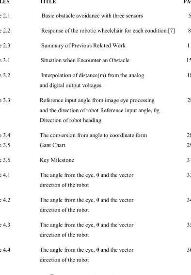
[image:11.595.109.504.228.795.2]Table 2.3 Summary of Previous Related Work 11
Table 3.1 Situation when Encounter an Obstacle 15
Table 3.2 Interpolation of distance(m) from the analog 18 and digital output voltages
Table 3.3 Reference input angle from image eye processing 28 and the direction of robot Reference input angle, θg
Direction of robot heading
Table 3.4 The conversion from angle to coordinate form 28
Table 3.5 Gant Chart 29
Table 3.6 Key Milestone 31
Table 4.1 The angle from the eye, θ and the vector 33 direction of the robot
Table 4.2 The angle from the eye, θ and the vector 34 direction of the robot
Table 4.3 The angle from the eye, θ and the vector 35 direction of the robot
xii Table 4.5 The angle from the eye, θ and the vector 37
direction of the robot
Table 4.6 Gain of controller for case 1, case 2 and case 3 38 Table 4.7 Coordinate with angle of the robot from Start point 39
xiii
LIST OF FIGURES
FIGURE TITLE PAGE
Figure 2.1 A robot integrated with three sensors 5
Figure 2.2 Seven light-sensitive resistors and five distance-measuring 8
sensors are mounted Figure 2.3 The basic structre of Hybrid automata 10
Figure 3.1 Flowchart for the project 14
Figure 3.2 Robot coordinate is the world frame 16
Figure 3.3 Sensor‟s coordinate in the robot frame 16
Figure 3.4 A rule diagram on Simulation process 17
Figure 3.5 Analog voltage output when an object is 18
detected by IR proximity sensorin the range of 5 to30 cm Figure 3.6 The coding for the conversion of infrared voltage 19
sensor to distance in centimenter Figure 3.7 Controller in Robot Simulation 20
Figure 3.8 IR range to point transformation. The blueline 22
will keep on followingthe redline and moves the robot to the free space Figure 3.9 The redline from the both right sensors is the 24
xiv
Figure 3.10 The implemetation of a state machine in the 26
Supervisor controller Figure 3.11 Part of the coding in the Supervisor controller 27
implemented from the Finite State Machine Figure 4.1 Graph of Reference Angle and Robot Angle 34
Figure 4.2 Graph of Reference Angle and Robot Angle 35
Figure 4.3 Graph of Reference Angle and Robot Angle 36
Figure 4.4 Graph of Reference Angle and Robot Angle 37
Figure 4.5 Graph of Reference Angle and Robot Angle 38
Figure 4.6 Graph of Robot Angle and Refrence angle due to case 1 39
Figure 4.7 Graph of Robot Angle and Refrence angle due to case 2 40
Figure 4.8 Graph of Robot Angle and Reference angle due to case 3 40
Figure 4.9 Starting point of the robot 41
Figure 4.10 Robot at the first obstacle 41
Figure 4.11 Robot along the wall 41
Figure 4.12 Robot at the secondobstacle 41
Figure 4.13 Robot at the end position 41
Figure 4.14 The arrow distance taken by the robot from 41
start point to final point Figure 4.15 Graph of Robot angle in radian versus time step 42
in seconds using switchingstrategy Figure 4.16 Switching state by the Supervisor in the Matlab 43
command window Figure 4.15 Graph of Robot angle in radian versus time step 44
in seconds using switching strategy Figure 4.17 Starting point of the robot 44
Figure 4.18 Robot moves ways at the first obstacle 44
Figure 4.19 Robot moves away from the wall 44
Figure 4.20 Robot moves away from thesecond obstacle 44
[image:14.595.106.503.76.785.2]xv Figure 4.22 The arrow distance covered by the robot from 44
start to final point
1
CHAPTER 1
INTRODUCTION
1.1 Research Background
In the world of mobile robot one of its application is the Robotic wheelchair. Robotic wheelchair can enhanced the capabilities of traditional powered devices by introducing control and navigational intelligence. The lives of many disabled people can be ease, particularly those with severe impairment, by increasing their range of mobility. It is important for the researcher to develop a high tech and very modern robotic wheelchair to help handicap people. The basic idea of the project comes when there is a situation when the user encounter an obstacle or wall for example. This would be a challenging for the researcher to develop an algorithm to avoid the obstacle either moving or static obstactle.
The needs of obstacle avoidance algorithm in any mobile robot will add the functionality to the robotic wheelchair to move and steer towards the direction of the located goal. A good control of strategy implementation with shared control for obstacle avoiding algorithm can help the robotic wheelchair to avoid the obstacle and help to reach the goal location.
2 1.2 Motivation
At the end of this project, we will be able to develop an obstacle avoidance algorithm with shared control that can be used for a robotic wheelchair that include switching system that capable in choosing the system priorities between Obstacle Avoidance Controller, Follow Wall Controller, and Go-to-Goal controller in order to reach the goal location by the user. These controllers are guided by the Supervisor controller based on finite state machine system which is basically a system that can switch the controller by their importance respectively according to the situation encounters by the robotic wheelchair.
1.3 Problem Statement
The robotic wheelchair is basically have the function to go to any direction by the signal from the controller. The user is in controlled for the robotic wheelchair. However the user will encounter difficulties in controlling the robotic wheelchair when facing with obstacle. For a robotic wheelchair sytem, one if its basic tasks should be avoiding obstacle. Obstacle avoidance is an important role in the design of self-navigating wheelchair with comfort, safety and smoothness as well. Therefore, the main difficulty is to develop an algorithm and strategy that are able to assist a robot wheelchair to recognise obstacles and to go around it by maintaining an realistic and safe distance.
1.4 Objectives
The objectives of the project are:-
To develop an obstacle avoidance algorithm with shared control for use in robotic wheelchair using Matlab robot simulator
3
To analyse the proposed obstacle avoidance algorithm for robotic wheelchair using Matlab robot simulator
1.5 Scope of Work
The scope of this project are
i. The controller of the obstacle avoidance algorithm in the robot simulator consists of
a) Go-to-Goal controller b) Avoid Obstacle controller c) Stop controller
d) Follow wall controller
e) Avoid Obstacle and Go-to Goal controller f) Supervisor for the all controllers above
ii. The simulation will only use a static obstacle environment as obstacle for the robot.
4
CHAPTER 2
LITERATURE REVIEW
2.0 Introduction
In the world of technology, robotic wheelchair has been in research for quite long by many researchers. The aims are basically to improve the current technology and safety to the user in order to make a user friendly wheelchair. This advanced research will help to improvised the robotic wheelchair to the another level of science and technology.
A robotic wheelchair is designed for people with impaired mobility must be able to help the user to navigate to the goal location within a certain workspace. The wheelchair is basically will be intergrated with multiple sensor used for mapping, path planning and obstacle avoidance strategy.[1]
5 2.1 Basic Concept for Obstacle Avoidance
Imagine a mobile robot with three sensos intergrated and from that we can make a logic gate based avoidance obstacle algorithm. Figure 2.1 shows a simple robot with three sensors.
[image:20.595.244.403.192.281.2]
Figure 2.1: A robot integrated with three sensors
Table 2.1: Basic obstacle avoidance with three sensors
Sensor Direction of
the robot
Two DC motors with two pins polarity (+ -)
Left Front Right Left Left Right Right
0 0 0 Forward 1 0 0 1
0 0 1 Forward 1 0 0 1
0 0 0 Right 1 0 1 0
0 0 1 Left 0 1 0 1
1 1 0 Front 1 0 0 1
1 1 1 Front 1 0 0 1
1 1 0 Right 1 0 1 0
1 1 1 Reverse 0 1 1 1
The most basic algorithm in term of logic gate showed in Table 2.1. It shows the direction of the robot when encounter an obstacle. However this simple logic method cannot be applied when encounter an obstacle with different type of length and angle. Therefore in order to overcome this situation a more advanced algorithm must be made. This will help the robot to navigate through a more complex obstacle.
Front
[image:20.595.81.530.346.584.2]6 2.2 Reviews of previous related works
The thesis by Marcelo R. Petry, Antonio Paulo Poreira describes on a robust, obstacle avoidance extension of the classic potential field methodology. Their algorithm is specially adapted to share the wheelchair‟s control with the user avoiding situation. The method relies on the idea of virtual forces generated by the user command (attractive forces) and by the objects detected on each ultrasonic sensor (repulsive forces), acting on the wheelchair.[2]
Some of the desired properties of shared control algorithm are:-
i) Avoid obstacles in real-time. Since wheelchairs operate in dynamic environments, it is not feasible to implement popular time-consuming, global path planners. Instead, such application is more suitable to approaches based on fast response like reactive/reflexive controls.
ii) Consuming low memory and processing algorithms are more likely to achieve a real-time reflexive behaviour in controlled systems.
iii) The safety and perception of the user is increase. Shared control approaches may consider qualitative evaluation of the wheelchair‟s overall behaviour in a quantitative reduction in the number of collision.
Summary of some classic obstacle avoidance methodologies developed in robotics.
1) Edge-Detection method
7 samples. Once measures are under a certain safety distance, the robot stops, take a panoramic scan, apply the edge-detection methodology and restart the cycle all over again.[3, 4]
2) Certainty Grid
Certainty grid (CG) method is basically a probabilistic representation of obstacles in a grid based world model. It has been developed for mobile robots in Stanford and CMU for more than ten years, and was originally designed to handle sonar‟s inaccuracies shortcomings [5]. In this method, the robot‟s work area is modeled as a 2-D array of square elements, called cells. Each cell of the grid contains a likelihood estimate (certainty value) that indicates confidence that an obstacle is placed within the corresponding region of space. Once readings are more likely to detect objects closer to the acoustic axis of the sonar, a probabilistic function updates more the certainty value in this region than in the other areas enclosed by the sensor [5, 6]. In spite of some improvements presented by CG methodology, some drawbacks can compromise its implementation in real-time applications. Firstly, the accuracy provided is too much dependent of the cell size. Secondly, as the robot moves over large areas, lots of memory and processing power are required, restricting the application of CG especially in some embedded systems. Finally, the subsequent robot‟s path shall be computed off-line, by a global pathplanning.
The next project report is about autonomous robotic wheelchair by Pin-Chun Hsieh. His research discussed on autonomous robotic wheelchair with collision avoidance navigation. The objective of this research is to demonstrate a robotic wheelchair moving in an unknown environment with collision-avoidance navigation. A real-time path-planning algorithm was implemented by detecting the range to obstacles and by tracking specific light sources used as beacons. Infrared sensors were used for range sensing, and light-sensitive resistors were used to track the lights. [7]
8
Figure 2.2: Seven light-sensitive resistors and five distance-measuring sensors are mounted on the sensor bracket with interface circuit board.[7]
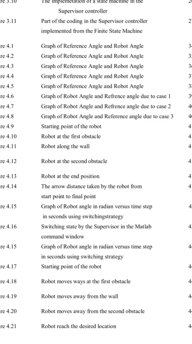
There are 32 conditions of the signal transmit from these five sensor with the sensors are arranged in the Figure 2.4. Table 2.1 shows the infrared sensor generates logic-high and logic –low to the Digital I/O PCMCIA Card.
Table 2.2: Response of the robotic wheelchair for each condition.[7]
Logic signal from Infrared Sensor Response of Robot
Left GP2D12
Left GP2D15
Right GP2D12
Right GPD12
Front GP2D15‟s Signal is L
Front GP2D15‟s Signal is L
L L L H Left turn Left turn
L L H L Left turn Left turn
L L H H Left turn Left turn
L H L L Right turn Right turn
L H L H Forward Stop
[image:23.595.77.550.523.750.2]9
L H H H Left turn Stop
H L L L Right turn Right turn
H L L H Forward Stop
H L H L Forward Stop
H L H H Forward Stop
H H L L Right turn Right turn
H H L H Forward Stop
H H H L Right turn Stop
H H H H Forward Stop
L L L L Forward Stop
A paper from Ioan Susnea, Viorel Minzu, Grigore Vasilu proposes an algorithm for real time obstacle avoidance, with low cost sonar or infrared sensors that can be implemented on embedded microcontrollers. The algorithm is called “the bubble rebound algorithm”. The obstacle within an area called “sensitivity bubble”around the robot can only be detected by the algorithm. Depending on the kinematics of the robot the sensitivity bubble size and shape are dynamically adjusted. The robot will “rebounds” towards a direction having the lowest density of obstacles, and continues its direction until desired goal becomes visible, or a new obstacle is encountered when detecting an obstacle. [8]
The advantages of this algorithm are
Uses very low computational load, and can be implemented on low-cost microcontrollers.
Can avoid any kind of static obstacles, and moving obstacles, like walking humans.

![Table 2.2: Response of the robotic wheelchair for each condition.[7]](https://thumb-us.123doks.com/thumbv2/123dok_us/136860.14004/23.595.87.542.69.311/table-response-robotic-wheelchair-condition.webp)
