Position Based Visual Servoing control of a
Wheelchair Mounter Robotic Arm using Parallel
Tracking and Mapping of task objects
Alessandro Palla
1, Alessandro Frigerio
1, Gabriele Meoni
1, Luca Fanucci
11Dept. of Information Engineering, University of Pisa, Italy
Abstract
In the last few years power wheelchairs have been becoming the only device able to provide autonomy and independence to people with motor skill impairments. In particular, many power wheelchairs feature robotic arms for gesture emulation, like the interaction with objects. However, complex robotic arms often require a joystick to be controlled; this feature make the arm hard to be controlled by impaired users. Paradoxically, if the user was able to proficiently control such devices, he would not need them. For that reason, this paper presents a highly autonomous robotic arm, designed in order to minimize the effort necessary for its control. In order to do that, the arm features an easy to use human - machine interface and is controlled by Computer Vison algorithm, implementing a Position Based Visual Servoing (PBVS) control. It was realized by extracting features from the images captured by the camera and fusing them with the distance from the target, obtained by a proximity sensor. The Parallel Tracking and Mapping (PTAM) algorithm was used to find the 3D position of the task object in the camera reference system. The visual servoing algorithm was implemented in an embedded platform, in real time. Each part of the control loop was developed in Robotic Operative System (ROS) Environment, which allows to implement the previous algorithms as different nodes. Theoretical analysis, simulations and in system measurements proved the effectiveness of the proposed solution.
Received on 28 February 2017; accepted on 11 May 2017; published on 17 May 2017
Keywords: Robotic Arm, Power Wheelchair, Visual Servoing, PBVS, Eye-in-Hand, Computer Vision, SIFT, Features extraction, PTAM, ROS, Human Machine Interface, Assistive Technology, Open-source
Copyright © 2017 Alessandro Palla et al., licensed to EAI. Thisis anopen access article distributedunder theterms of theCreativeCommonsAttributionlicense(http://creativecommons.org/licenses/by/3.0/),whichpermitsunlimited use,distributionandreproductioninanymediumsolongastheoriginalworkisproperlycited.
doi:10.4108/eai.17-5-2017.152545
1. Introduction and State of the Art
The number of people affected by different motor skill impairments is constantly increasing. The most com-mon diseases are the Spinal Muscular Atrophy (SMA), Muscular Dystrophy, Multiple Sclerosis and Duchenne Dystrophy or Cerebral Palsy. In addition to these dis-eases, there are many other reasons that can cause mobility impairments, like the injuries derived by a car/motorbike/work accident.
For those people, the possibility of autonomously mov-ing is an important improvement in their psycholog-ical status, because it gives them independence and remarkable physical and psychological sense of well-being. For those who are unable to self-propel a manual
∗
Corresponding author. Email:[email protected]
wheelchair, electric-powered wheelchairs are often a suitable option. Especially in outdoor scenarios, Elec-tronic Power Wheelchairs (EPWs) are a perfect mean to improve the mobility experience of people with motor skill impairments.
The user typically controls the wheelchair by a joystick. A multitude of alternative control options such as proximity switches, sip-n-puff, head arrays, infrared switches and magnetic angle sensors exist for those unable to use the standard joystick interface. Nevertheless, controlling a power wheelchair is still a quite difficult task for people with low vision, visual field reduction, spasticity, tremors, or cognitive deficits. For such reason, a large number of solutions have been studied by researchers since the 1980s in order to give also these people a higher degree of autonomy, such
1
on
Ambient Systems
Research Article
EAI Endorsed Transactions on
Ambient Systems
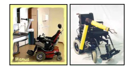
Figure 1. Manusand RaptorRoboticArm
solutions lead to the born of the smart wheelchairs by using technologies originally thought for mobile robots. A smart wheelchair typically is a standard power wheelchair with the addition of a set of sensors and actuators. A computer unit collects environmental data and process them in order to find obstacles and hazards. Authors in [1] show one of the first examples of autonomous wheelchairs, equipped with sonars and a vision system to identify landmarks and correct the trajectory in a hallway.
Recently, more sophisticated systems also implement robotic arms for gesture emulation, such as interacting with objects like bottles, glasses, buttons etc. On the market there are just a few examples of Wheelchair Mounted Robotic Arm (WMRA) systems, such as:
• The Manus WMRA (Figure 1a), manufactured by Exact Dynamics. This system, was developed since the mid of 80s and entered in production at the beginning of the 90s. It consists in a 6 Degrees of Freedom (DoFs) arm that can be programmed in a manner comparable to industrial robotic manipulators [2].
• The Raptor WMRA (Figure 1b), manufactured by Applied Resources. This manipulator is much simpler in respect of Manus WMRA. Indeed, it has 4 DoFs robotic arm that can be directly controlled with either a joystick or a 10-button controller [3]. Typically, the joystick that controls the manipulator arm is located on the armrest opposite to the input device that controls the steering of the power wheelchair.
• Jaco Robotic Arm by Kinova. This arm has 6 DoFs and can be equipped with a gripper with two or three under-actuated finger. The structure in carbon fiber allows the robotic arm to be very lightweight (5.2 Kg). The producer provided control software allows sixteen different movements possible, like opening a door, drinking a beer, etc.
Those robotic arms and systems like the one presented in [3] require the user to manually control
the arm position and move it to the desired place. When the manipulator is controlled by a joystick or a similar control systems, tasks like pressing button could be very difficult for people with severe motor skill impairments, since they require high accuracy and precise gestures.
Authors in [4] follow a very promising Eye-in-Hand approach designing a WMRA system, using a 7-DoFs robotic arm with a camera placed in the end-effector. The robotic arm control system uses an Image Based Visual Servoing (IBVS) approach described with a Speeded Up Robust local Features detection (SURF) algorithm in order to detect the features from the camera picture. In an IBVS system, the arm is controlled through the information about the distance of the object from a desired position in the image plane, without the necessity of a pose estimation of the target.
Authors in [5], [6] show a robotic arm capable to recognize and press buttons. In their works two different approaches have been followed to control the system:
• An Image Based Visual Servoing (IBVS) approach, where the controller use the features in the camera image space to close the feedback loop.
• A Position Based Visual Servoing (PVBS) approach, where the image feature are used to perform the pose of the object in the camera reference frame.
The fact that the human-machine interface (HMI) requires only one touch to perform the button pressing task is one of the most interesting feature of those works. Indeed, it makes the control of the arm very simple. In order to do that, the video captured by the camera is processed and showed on the screen; the user just have to select the button he wants the robotic arm to press. After that, the manipulator will move autonomously to the target.
In addition, the use of a Linux based device and a monocular camera increases the portability of the system, also leading to a low-cost, light and small solution. Nevertheless, such simple setup will have very reduced computational capability due to the performance of the involved board, which leads to limited computer vision performance.
Figure 2. Jaco RoboticArm
Figure 3. The Raspberry Pi Setup, includingCamera Module
and HCSR-04 sensor
Task AccuracyArm ComputerVisionComplexity DoFs
Doorknocking Low Not required 3
Press Button Medium Simple Shape(Button) at least 5
Turnon/o˙PC Medium Simple Shape(Button) at least 5
Table 1. Robottask vs complexity
been developed in order to be flexible, portable and multi-platform. It is written in C/C++ and Python.
The paper is structured as follows: in Section 2 the robotic arm architecture is described; starting from that, it will focus on the Human Machine Interface (Section 3) and on the Computer Vision routines (Section 4). Accuracy of the object pose estimation algorithm and paper conclusion are discussed in Sections5and7.
2. System Description
The utilized hardware consists of:
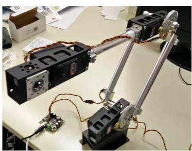
• A 5 Degrees of Freedom (DOFs) robotic arm as shown in Figure5
• A Raspberry Pi 3 Model B
• A Raspberry Camera Module V1.3
• A Linux Laptop
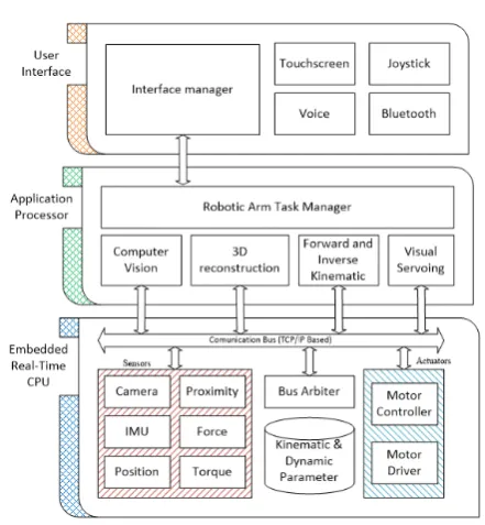
Figure 4. ROS based softwarestack
• A HCSR-04 Ultrasonic Proximity Sensor
• A Force Sensitive Resistor (FSR)
The Raspberry Camera Module is a light camera capable of capturing video at up to 1080p at 30 fps. Thanks to its small dimensions it can be easily placed on the end effector of a robotic arm without interacting with the motor movements. The HCSR-04 proximity sensor is also connected to the Raspberry Pi 3 Board, using the GPIO port. This sensor provides a wide range of measurements, from 2 cm to 400 cm with an accuracy of 3 mm. Figure 3 shows the complete setup of the Raspberry Pi module, which is connected via Wi-Fi to a Linux-based computer. The FSR is needed to detect the contact between the arm end effector and the target. Table 1 summarizes the tasks performed by the robotic arm in terms of accuracy, computer vision complexity and number of necessary DoFs. The interaction with an elevator panel is definitively the most complex and computationally intensive task. Indeed, the computer vision algorithm has to:
• Detect the button in the recorder scene
• Track the button between consecutive frames
• Estimate the button position in the camera frame
As previously described, the software architecture is developed in a ROS environment, both on the Raspberry Pi and on the Linux Workstation, as shown in Figure 4. The Raspberry board holds multiple ROS nodes, acquiring data from the sensors and control the arm servo actuators. The Workstation runs the Computer Vision, and the robot Forward and Inverse
3 EAI Endorsed Transactions Ambient Systemson
Figure 5. The roboticarmwithoutthe end-e˙ector
Figure 6. End e˙ector with the camera module, force and
proximitysensor
Kinematic and the Visual Servoing algorithm. Figure5 shows the robotic arm used in this project, while Figure 6shows the end effector on which the camera module is mounted.
A graphical user interface (GUI) has been developed to allow the button selection and the simple robotic arm controlled by the user. The GUI will be described in Section3.
3. Graphical User Interface
The Graphical User Interface (GUI) has been designed in order to provide a simple and effective human-robotic arm interface and an easy control of the system. Figure7shows a screenshot of the GUI. On the left, the image captured from the camera is shown. On the top-right, the two virtual joysticks allow to control the end effector in the XYZ direction and to control the rotation of the arm. These controls are needed if the target is not included in the camera frame. In such situation, the user can simply move the arm in order to focus the desired object. Since the joysticks are required only to focus the target in the camera frame, high accuracy in the user manipulation skills is not required. On the bottom right, the last two buttons allows to power on/offthe actuators.
Figure 7. RoboticarmGraphical User Interface
The GUI is implemented as a Web Service. In such way, devices like tablets or PC can connect to the node via WiFi, increasing the portability of the human machine interface. From the ROS point of view, the GUI is a single node that sinks the informations from the sensors information and streams commands in the ROS TCP/IP bus.
The user selects the desired target object by pressing it on the GUI image. In this way, performing the desired task is extremely simple, because it only requires one touch. A Region Of Interest (ROI) is selected around the clicked point and several features are extracted inside the ROI. These features are necessary to track the object between consecutive frames and to perform the PBVS control of the system, as shown in Section4
4. Position Based Visual Servoing
The control algorithm is shown in Figure8, as defined in [7]. As described in Section 3, after the object selection several features are extracted in a ROI around the clicked point in order to perform an automatic control of the system. The system is not based on the recognition of the button among different frames but the extracted features are used to track the position of the object in the camera frame. This kind of control is called Position Based Visual Servoing, because it extracts the position in the 3D world of the object by means of the features.
4.1. ComputerVision
It is possible to separate the computer vision algorithm into three different tasks:
• Features extraction, using the Scale-Invariant Feature Transform (SIFT) [8] algorithm;
Cartesian Control Law
Motor Driver Pose Error
+
-Image Feature Extraction Pose
Estimation Cx
*
Measured Pose
f Motors Trajectory
Video Cx
Desired Pose
Figure 8. PositionBased ImageServoingblockdiagram[7]
Figure 9. SIFT extracted featuresmatchedto the ROIkeypoints
• Scale estimation and 3D re-projection of the tracked button.
SIFT algorithm is applied on a small Region of Interest (ROI) around the selected button. In the following frames, the Computer Vision node will extract SIFT features and match them to the ROI ones, by using Fast Library Approximate Nearest Neighbor (FLANN) [9]. It realizes the visual tracking of the button. Figure9shows the extracted keypoints matched to the original button ones.
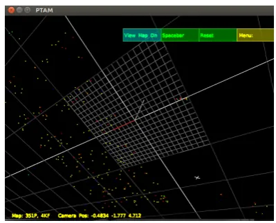
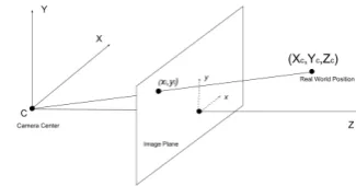
Parallel Tracking and Mapping [10] (PTAM) algo-rithm is used to obtain the 3D position of the 2D SIFT feature in the camera frame. The PTAM algorithm exploits the motion of the camera to generate a point cloud of features, as shown in Figure 10. In order to find the 3D button position, it is necessary to relate the tracked SIFT feature with the PTAM point cloud. For that reason, the PTAM point cloud is projected into the image plane, as shown in Figure11. Equation 1 shows the relationship between the two coordinate systems. The parametersfxandfyare the focal lengths of the camera,cxandcyare the camera optical centers. Those parameters are extracted via the OpenCV camera calibration routine.
xi =fx∗ Xc Zc
+cx
yi =fy∗ Yc Zc
+cy
(1)
Figure 10. Generated Pointcloudby PTAM
However, the motion of the camera is not easily predictable, because of motion artifacts, robot dynamics uncertainly, friction, gearing backslash, etc. This non-linear behavior makes the point cloud coordinates pre-cise but not accurate, since the 3D points coordinates are scaled by an a-priori unknown factor λ [11]. In particular, we can model the PTAM measurements as Gaussian Random Variable with standard deviation σP T AM and a meanλµi, whereµi is the true position of the feature in the 3D space, andλis an unknown scale factor. Equation2shows thezcomponent distribution of a PTAM point. Because of the previous consideration, λfactor is the same for all thexyzcomponents.
zP T AM ∼ N(λµi, σP T AM2 ) (2) Using a proximity sensor is possible to obtain a better estimation of the true distance of the objects. This is particularly true in our scenario, since all the features lie on the same plane. Equation 3 shows the distance distribution from the proximity sensor:
zprox∼ N(µi, σprox2 ) (3) It is possible to combine the output of the two methods by means of a Maximum-Likelihood Estimation method [11] in order to obtain an estimation ofλ and correct the PTAM points’ coordinates. This is equivalent to minimize the negative log-likelihood function for a given numbernof acquisitions:
L(µi, λ) = 1 2
n X
i=1
||zP T AM[i]−λµi||
σP T AM2 +
||zprox[i]−µi||
σprox2
(4) The 3D corrected points are then projected to the camera plane using Equation 1, and the SIFT points close to the target are selected. In order to find theZc coordinate of the object, it is possible to use the PTAM features that lie in the ROI to interpolate a plane in the camera coordinate system. From 3D plane equation in
5 EAI Endorsed Transactions Ambient Systemson
Figure 11. Relation between point coordinatein camera and
imagereferencesystems
Figure 12. PBVS controlloop
5, the a,b,c,d coefficients can be calculated by using the Least Mean Square Methods:
a∗Xc+b∗Yc+c∗Zc+d= 0 (5)
These parameters are used to find theZccoordinate of the object:
Zc=−
d
a∗xi −cx fx
+b∗yi −cy
fy +c
(6)
The real world button position is finally calculated in Equation 7 by inverting the Equation 1 and by using theZcobtained in Equation6.
Xc=
(xi−cx)∗Zc fx
Yc=
(yi−cy)∗Zc fy
(7)
4.2. RoboticArmControl
Figure 12 shows the architecture of the PBVS control loop. The position errorxis defined as:
x= (Cx−C ∗
x) (8)
where C∗x is the measured object pose in the camera frame, and Cx is their desired final pose. In this scenario, Cx is equal to the distance between the camera and the robot finger. A Proportional-Integral-Derivative (PID) controller generates the camera speed vc. The motor speed can be calculated by using the
inverse differential kinematic [12]:
˙
q=Jc†(q)·vc (9)
where ˙q is the actuator speed and the Jc† is the pseudoinverse matrix of the manipulator Jacobian, expressed in the camera frame. Since the evaluation of the Jacobian matrix requires the actual position of the joints, each motor is provided with a position sensor. If the end effector orientation is constrained in all three directions, the robotic arm has not enough DoFs to perform the required task. In this situation, the matrix J†
c becomes the LMS solution of the equation.
vc=Jc(q)·q˙ (10)
If the end effector is not constrained in orientation, the Jacobian matrix in Equation10 has more columns than rows, leading to an infinite number of possible solutions. By choosing the minimum norm solution, is possible to achieve the fastest response, since the norm of ˙q is minimized. In this scenario, the Jacobian pseudoinverse becomes the Moore-Penrose right pseudoinverse [12]:
Jc†=JcH·(Jc·JcH) −1
(11)
5. Results
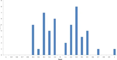
The system was tested in a controlled environment: the camera is positioned at a distance in the range of [18−50] cm. Figure13shows the measurements taken on the principal camera axis and Figure14 shows the error distribution. Table 2 shows the performance of the system in this situation. Since the PBVS is a closed-loop system, this error is divided by the closed-loop gain. It is possible to find the proper PID coefficient in order to make that error small and appropriately neglectable.
15 20 25 30 35 40 45
17 22 27 32 37 42 47
Meas
ur
ed
dis
tance (c
m)
Real distance (cm)
Figure 13. Real vs. Measured Distance between End E˙ector
MinError Max Error Std Deviation
Mean Absolute
Error R2
0.05 cm 0.95 cm 0.36 cm 0.31 cm 0.99 %
Table 2. System performanceon principalaxis measurement
Figure 14. MeasuredDistanceErrorHistogram
6. Acknowledgment
This research was supported by Fondazione Cassa di Risparmio di Lucca in the framework of the project "RIMEDIO: Il braccio Robotico Intelligente per Migliorare l’autonomia delle pErsone con DIsabilità mOtoria".
7. Conclusion
This paper shows a Position Based Visual Servoing system based on a monocular camera and a 3D feature extraction. Accurate informations of the 3D surroundings can be extracted by means of PTAM algorithm. It allows to a simple implementation of the arm control algorithm to generate the arm movement trajectory using a PBVS approach. The task object position is extracted by fusing the information coming from the camera and the proximity sensor. In addition, a simple and easy to use human-machine interface allows to easily control the robotic arm also by people with high motor skill impairments. The use of the ROS environment leads to a modularity of the software architecture, making the implementation of new features possible without modifying the other ROS nodes. Finally, ROS and all the other softwares and libraries are open source, and realize a low-cost and
portable system in combination with the Raspberry Pi and Camera Module.
References
[1] R. L. Madarasz, L. C. Heiny, R. F. Cromp, and N. M. Mazur, “The design of an autonomous vehicle for the disabled,” Robotics and Automation, IEEE Journal of, vol. 2, no. 3, pp. 117–126, 1986.
[2] H. Eftring and K. Boschian, “Technical results from manus user trials,” inICORR’99: International Conference on Rehabilitation Robotics, 1999.
[3] M. Hillman and A. Gammie, “The bath institute of medical engineering assistive robot,” in Proc. ICORR, vol. 94, 1994, pp. 211–212.
[4] M. Elarbi-Boudihir and K. A. Al-Shalfan, “Eye-in-hand/eye-to-hand configuration for a wmra control based on visual servoing,” in Electronics, Control, Measurement, Signals and their application to Mechatronics (ECMSM), 2013 IEEE 11th International Workshop of. IEEE, 2013, pp. 1–6.
[5] A. Palla, A. Frigerio, L. Sarti, and L. Fanucci, “Embedded implementation of an eye-in-hand visual servoing control for a wheelchair mounted robotic arm,” IEEE ICTS4eHealth, 2016.
[6] A. Palla, A. Frigerio, G. Meoni, and L. Fanucci, “Object detection and spatial coordinates extraction using a monocular camera for a wheelchair mounted robotic arm,”GoodTech2016, 2016.
[7] S. Hutchinson, G. D. Hager, and P. I. Corke, “A tutorial on visual servo control,”IEEE transactions on robotics and automation, vol. 12, no. 5, pp. 651–670, 1996.
[8] D. G. Lowe, “Object recognition from local scale-invariant features,” in Computer vision, 1999. The proceedings of the seventh IEEE international conference on, vol. 2. Ieee, 1999, pp. 1150–1157.
[9] M. Muja and D. G. Lowe, “Scalable nearest neighbor algorithms for high dimensional data,”Pattern Analysis and Machine Intelligence, IEEE Transactions on, vol. 36, 2014.
[10] G. Klein and D. Murray, “Parallel tracking and mapping for small AR workspaces,” inProc. Sixth IEEE and ACM International Symposium on Mixed and Augmented Reality (ISMAR’07), Nara, Japan, November 2007.
[11] J. Engel, J. Sturm, and D. Cremers, “Scale-aware navigation of a low-cost quadrocopter with a monocular camera,”Robotics and Autonomous Systems, vol. Volume 62, 2014.
[12] B. Siciliano, L. Sciavicco, L. Villani, and G. Oriolo,
Robotics: modelling, planning and control. Springer Science & Business Media, 2010.
7 EAI Endorsed Transactions Ambient Systemson