Joint Source Coding, Unity Rate Precoding and FFH-MFSK
Modulation using Iteratively Decoded Irregular Variable
Length Coding
Sohail Ahmed, Robert G. Maunder, Lie-Liang Yang, Soon Xin Ng and Lajos Hanzo School of ECS, University of Southampton, SO17 1BJ, UK.
Tel: +44-23-8059 3364, Fax: +44-23-8059 4508
Email:{sa03r,rm02r,lly,sxn,lh}@ecs.soton.ac.uk; http://www-mobile.ecs.soton.ac.uk
Abstract— Serially concatenated and iteratively decoded Irregular Variable Length Coding (IrVLC) combined with precoded Fast Fre-quency Hopping (FFH) M-ary Frequency Shift Keying (MFSK) is considered. The proposed joint source and channel coding scheme is capable of low Signal-to-Noise Ratio (SNR) operation in Rayleigh fading channels contaminated by Partial Band Noise Jamming (PBNJ). The IrVLC scheme is comprised of a number of component Variable Length Coding (VLC) codebooks employing different coding rates for encoding particular fractions of the input source symbol stream. These fractions may be chosen with the aid of EXtrinsic Information Transfer (EXIT) charts in order to shape the inverted EXIT curve of the IrVLC codec so that it can be matched with the EXIT curve of the inner decoder. We demonstrate that using the proposed scheme near-zero bit error ratio may be achieved at low SNR values and the IrVLC based scheme yields a further gain of up to 0.3dB over the identical-rate single-class VLC based benchmarker scheme.
I. INTRODUCTION
In analogy to Irregular Convolutional Coding (IrCC) [1], the family of so-called Irregular Variable Length Coding (IrVLC) [2] employs a number of component VLC codebooks having different coding rates [3] for encoding particular fractions of the input source symbol stream. With the aid of EXtrinsic Information Transfer (EXIT) charts [4], the appropriate lengths of these fractions may be chosen in order to shape the inverted EXIT curve of the IrVLC codec such that it does not cross the EXIT curve of the inner channel codec. In this way, an open EXIT chart tunnel may be created even at low values of Signal-to-Noise Ratio (SNR).
Fast Frequency Hopping (FFH) M-ary Frequency Shift Keying (MFSK) has been shown to efficiently combat Partial Band Noise Jamming (PBNJ) [5]. By transmitting every symbol using multiple hops, FFH systems exploit both time as well as frequency diversity. Furthermore, in the FFH-MFSK receiver, suitable diversity combining method may be invoked to suppress effects of PBNJ. We employ clipped combining [5] for this purpose.
The concept of extrinsic information exchange between an M -ary orthogonal demodulator and a Soft-In-Soft-Out (SISO) decoder has been investigated in [6], [7]. In [7], further insights have been provided with the aid of EXIT chart analysis. However, in published literature, little attention has been focused on investigation of SISO decoding in noncoherent MFSK-based schemes, especially the FFH-MFSK arrangement.In this contribution, we investigate for the first time an IrVLC coded and precoder assisted FFH-MFSK system com-municating in an uncorrelated Rayleigh fading channel contaminated by PBNJ. By employing EXIT charts, we investigate the concatenation
The financial support of the EPSRC, UK and EU under the auspices of the Phoenix and Newcom projects and of Higher Education Commission, Pakistan is gratefully acknowledged.
of the FFH-MFSK demodulator, unity rate decoder and the IrVLC outer decoder in order to attain a good performance even at low SNR values.
The rest of this paper is structured as follows. In Sec. II, the system considered is described and the concept of joint source and channel coding is elaborated. In Sec. III, the soft metrics are derived and the iterative decoding process is discussed with emphasis on the EXIT characteristics of the precoder and the demodulator. In Sec. IV, the choice of IrVLC code parameters is discussed with the aid of EXIT charts and Bit Error Ratio (BER) results are discussed. Finally, in Sec. V, we present our conclusions.
II. SYSTEMOVERVIEW
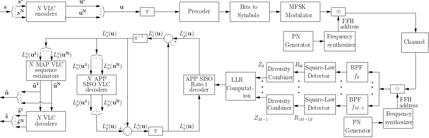
In this section we consider two serially concatenated and iteratively decoded joint source and channel coding schemes. Specifically, we consider an IrVLC codec and an equivalent regular VLC-based bench-marker in this role. We refer to these schemes as the IrVLC-and the VLC-FFH-MFSK arrangements, respectively. The schematic that is common to both of these schemes is shown in Fig. 1.
Joint source and channel coding The schemes considered are designed for facilitating the low BER transmission of source symbol values over an uncorrelated Rayleigh fading channel. We consider K = 16-ary source symbol values that have the probabilities of occurrence that result from the Lloyd-Max (LM) quantization [8] of independent Laplacian distributed source samples. More explicitly, we consider the 4-bit LM quantization of a Gaussian source. Note that these occurrence probabilities vary by more than an order of mag-nitude between 0.0023 and 0.1616. These probabilities correspond to entropy or average information values between 2.63 bits and 8.74 bits, motivating the application of VLC and giving an overall source entropy ofE= 3.47bits/VLC symbol.
In the transmitter shown in Fig. 1, the source symbol frame s comprises ofJ 4-bit source symbols having theK= 16-ary values {sj}Jj=1∈[1. . . K]. These source symbols are decomposed intoN number of components {sn}Nn=1, where we opted for N = 16in the case of the IrVLC-FFH-MFSK scheme andN = 1in the case of the VLC-based scheme. The number of symbols in the source symbol frames that are decomposed into the source symbol frame componentsnis specified asJn, where we haveJ1=Jin the case of the VLC-based scheme. By contrast, in the case of the IrVLC-based scheme, the specific values of {Jn}Nn=1 may be chosen in order to shape the inverted EXIT curve of the IrVLC codec so that it does not cross the EXIT curve of the precoder, as will be detailed in Sec. IV.
Each of the N number of source symbol frame components {sn}N
.
.
.
.
.
.
.
.
.
.
.
.
π π
NMAP VLC
estimatorssequence NAPP
decoders SISO VLC
decodersNVLC
NVLC encoders
s s
1
sN
⊕
+ Loe(u) Lo
p(u) − Lo
a(u) π−1
+
Li a(u) − Li
e(u) Lip(u)
Rate-1 APP SISO
decoder
˜uN
˜s ˜s
1
˜sN
uN
u1
u
Lo a(uN) Lo
a(u1)
˜u1
Lo a(uN) Lo
a(u1)
Lo p(uN) Lo
p(u1) ˜u
LLR Precoder
Detector BPF
f0
BPF PN
Generator
PN
Channel MFSK
Modulator
Z0
synthesizer Frequency
R0l
R(M−1)l ZM−1
Detector Combiner
Diversity Symbols
fM−1
synthesizer Frequency Bits to
Combiner
Diversity Square-Law
Square-Law
Generator FFH
FFH address
address
[image:2.595.89.524.56.196.2]Computat-ion
Fig. 1. Schematic of the IrVLC- and VLC-based schemes employed in conjunction with FFH-MFSK. In the IrVLC coded schemeN= 16, whilstN= 1 in the VLC-coded scheme.
range of coding rates{Rn}Nn=1∈[0,1]. The specific source symbols having the value of k∈[1. . . K]and encoded by the specific VLC codebookVLCn are represented by the codewordVLCn,k, which has a length of In,k bits. The Jn number of VLC codewords that represent the Jn number of source symbols in the source symbol frame component sn are concatenated to provide the transmission frame componentun={VLCn,snjn}Jjnn=1.
Owing to the variable length of the VLC codewords, the number of bits comprised by each transmission frame component un will typically vary from frame to frame. In order to facilitate the VLC decoding of each transmission frame componentun, it is necessary to explicitly convey its lengthIn=Jjnn=1In,s
n
jn to the receiver with
the aid of side information. Furthermore, this highly error-sensitive side information must be reliably protected against transmission errors. This may be achieved using a low rate block code or repetition code, for example. For the sake of avoiding obfuscating details, this is not shown in Fig. 1.
TheN number of transmission frame components{un}Nn=1 are concatenated at the transmitter, as shown in Fig. 1. The resultant transmission frameuhas a length of Nn=1In bits. Following the interleaverπ, the transmission frameuis precoded and then precoded bits are converted toM-ary symbols [9], which are transmitted by the FFH-MFSK modulator of Fig. 1. In the FFH-MFSK transmitter the MFSK signal modulates the carrier generated by a frequency synthe-sizer, which is controlled by theL-tuple FFH address generated by a pseudo-noise (PN) generator, whereLis the number of frequency hops per symbol. The hop intervalThis related to the symbol interval Ts byTh=Ts/L. The separation between adjacent frequency tones is assumed to beRh= 1/Th, which also represents the bandwidth occupied by a single FFH-MFSK tone.
The channel is assumed to be a frequency-flat Rayleigh fading medium for each of the transmitted frequencies. Furthermore, we assume that the separation between the adjacent frequencies is higher than the coherence bandwidth of the channel. Therefore, all FFH tones conveying the same symbol experience independent fading.
The transmitted signal is also corrupted by Additive White Gaus-sian Noise (AWGN) and a PBNJ signal having single-sided power spectral densities of N0 and NJ, respectively. We assume that the PBNJ signal jams a fraction0≤ρ≤1of the total spread spectrum bandwidthWss. We also assume that the PBNJ signal is contiguous and hence all theM FSK tones of a particular band are jammed, if the jamming signal is present in that band. Thus, the probability that a band or a tone is jammed is given byρ, while the probability that the band is not jammed is(1−ρ).
The receiver schematic is also shown in Fig. 1, where the frequency de-hopper, which is identical to and aligned with the frequency hop-per of the transmitter, de-spreads the received signal by exploiting the knowledge of the transmitter’s unique FFH address. The demodulator of Fig. 1 is comprised ofMbranches, each corresponding to a single MFSK tone and consisting of a square-law detector [10] as well as a diversity combiner, which performs clipping followed by linear combining on the signals received in all hops. The process of clipping is expressed by [5], [11]
f(Rml) =
C, ifRml≥C
Rml, otherwise, (1)
whereCrepresents an appropriately chosen clipping threshold. The decision variable recorded after clipped combining is given by
Zm= L−1
l=0
f(Rml), m= 0,1, ..., M−1. (2)
At the output of the diversity combiner, the corresponding symbol probabilities and log-likelihood ratios (LLRs) are computed, as explained in the following section, which are then fed to the unity-rate decoder of Fig. 1.
III. ITERATIVE DECODING
In this section we discuss how soft information is derived from the channel observation and how iterative decoding is carried out by exchanging extrinsic information between the precoder and the outer decoder seen in Fig. 1.
Derivation of soft information In order to compute the LLRs, we need the probability that themth symbolsm was transmitted, m= 0, . . . , M−1, given that the signalZ=Z0, Z1, . . . , ZM−1, which represents the set ofM outputs of the diversity combiners of Fig. 1, is received. This probability is given by
P(sm|Z) =p(Z|spm(Z)P)(sm), (3)
where p(Z|sm) is the Probability Density Function (PDF) of the received signalZ, given thatsmis transmitted. Furthermore,P(sm)
is the a priori probability of the symbol sm, while p(Z) =
M−1
m=0p(Z|sm)P(sm) is the probability of receiving signal set
p(Z|sm)is given by
p(Z|sm) =fZm(xm|sm) M−1
n=0,n=m
fZn(xn|sm), (4)
wherefZn(xn|sm)represents the PDF of thenth diversity combiner output,n= 0,1, . . . , M−1, given thatsm is transmitted. In [11], using the PDFs and the Characteristic functions [10] of the square-law detector outputs, we derived a simplified expression for thep(Z|sm)
of (4), which is given by
p(Z|sm) = exp
xmγh
1 +γh
, (5)
whereγh=bREb/(N0L)is the SNR per hop,R is the code rate, Ebis the transmitted energy per bit andb= log2M is the number of bits per MFSK symbol. Upon inserting (5) in (3), we can derive the corresponding symbol probabilities. The resultant bit probabilities can be derived from the symbol probabilities, assuming the bits-to-symbol mapping of [9] and finally, using the bit probablities, the LLRs can be computed [4].
Note that above, we have derived the soft information from the channel’s output observations, assuming a somewhat simplistic but tractable interference-free channel. Moreover, although clipped combining is employed in the receiver, our analysis assumes linear combining, using no clipping at the receiver. This assumption has been stipulated for further simplifying the analysis and is supported by the observation that clipping is an operation performed to reduce effects of PBNJ. We will demonstrate in Sec. IV, that valuable performance improvements can be achieved using this sub-optimal soft information.
EXIT characteristics of demodulator and precoderLet us now study the mutual information (MI) characteristics of the FFH-MFSK demodulator using EXIT curves [4]. We assume that the a priori information may be sufficiently accurately modelled by a Gaussian distribution [4]. Moreover, all MI measurements were made using the histogram method based approximation of the true distribution [4]. Note that in Fig. 1, L(·) denotes the LLRs of the bits concerned, where the superscript i indicates inner decoder (or demodulator), while o corresponds to outer decoding. Additionally, a subscript denotes the dedicated role of the LLRs, witha,pandeindicatinga priori,a posterioriand extrinsic information, respectively.
In Fig. 2, the MI transfer characteristics of the FFH-MFSK demodulator recorded in a Rayleigh fading channel are shown for various M values, assuming L = 3 and Eb/N0 = 8dB. In order to portray these EXIT curves in the correct perspective, the inverted EXIT curve of a half-rate Recursive Systematic Convolutional (RSC) decoder characterised by the octal generator polynomial of (7,5) is also shown. Fig. 2 demonstrates that the FFH-MFSK demodulator yields low-gradient EXIT curves for most values of the modulation order M. When the SNR is sufficiently high, the EXIT curves are shifted upward in the EXIT plane and hence an arbitrarily low BER may be achieved. However, this would be achieved at the cost of having a large area between the demodulator’s and the RSC decoder’s EXIT curves, implying that the scheme operates far from capacity.
In order to generate an inner decoder EXIT curve that is more conducive to fruitful concatenation with the outer IrVLC decoder, we employ a precoder, characterised by the generator polynomial of
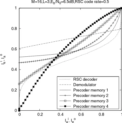
1/(1 +D) [12], between the IrVLC encoder and the FFH-MFSK modulator, as shown in Fig. 1. The MI transfer characteristics of the unity-rate decoder recorded for various values of precoder memory are shown in Fig. 3. It can be seen that the precoder renders the
0 0.2 0.4 0.6 0.8 1
0 0.2 0.4 0.6 0.8 1
I
d e
, I
o a
Ida, Ioe
L=3,Eb/N0=8dB,RSC code (G,Gr)=(7,5),code rate=0.5
M=2 M=8 M=32
[image:3.595.318.519.69.278.2]RSC decoder Demodulator
Fig. 2. Extrinsic information transfer characteristics of FFH-MFSK demod-ulator in Rayleigh fading channel, assuming variousM values.
0 0.2 0.4 0.6 0.8 1
0 0.2 0.4 0.6 0.8 1
Ie i, I
a
o
Ia
i
, Ie
o
M=16,L=3,Eb/N0=6.5dB,RSC code rate=0.5
RSC decoder Demodulator Precoder memory 1 Precoder memory 2 Precoder memory 3 Precoder memory 4
Fig. 3. Extrinsic information transfer characteristics of the rate-1 decoder in Rayleigh fading channel, assuming various values of the precoder memory.
channel to appear recursive [12], and hence has steeper EXIT curves than the stand-alone demodulator. Furthermore, as the precoder’s memory is increased, the EXIT curves become steeper. Moreover, in contrast to the demodulator, the rate-1 decoder’s EXIT curves do indeed reach the(1,1) point in Fig. 3, implying that the precoder allows the iterative decoding to converge to an arbitrarily low BER. In our subsequent analysis, we opt for a memory 3 precoder.
[image:3.595.314.518.326.531.2]SinceN number of separate VLC encoders are employed in the transmitter,Nnumber of separate VLC decoders are employed in the corresponding receiver seen in Fig. 1. In parallel to the composition of the bit-based transmission frame u from N number of VLC components, the a priori LLRs Loa(u) are decomposed into N number of components, as shown in Fig. 1. This is achieved with the aid of the explicit side information that we assume for conveying the number of bits In in each transmission frame component un. Each of the N number of VLC decoders is provided with the a priori LLR sub-frame Loa(un) and in response it generates the a posterioriLLR sub-frameLop(un),n∈[1. . . N]. Thesea posteriori LLR sub-frames are concatenated in order to provide thea posteriori LLR frame Lop(u), as shown in Fig. 1.
During the final decoding iteration,N number of bit-based MAP VLC sequence estimation processes are invoked instead of single-class APP SISO VLC decoding, as shown in Fig. 1. In this case, each transmission frame component un is estimated from the cor-responding a priori LLR frame component Loa(un). The resultant transmission frame component estimates ˜un may be concatenated to provide the transmission frame estimate ˜u. Additionally, the transmission frame component estimates ˜un may be VLC decoded to provide the source symbol frame component estimates˜sn. Since this process cannot exploit the knowledge that the source symbol frame component sn comprises of Jn number of source symbols, the resultant source symbol frame component estimate˜sn may not contain Jn number of source symbols. For the sake of preventing the resultant loss of synchronisation that this would imply, source symbol estimates are appropriately removed from, or appended to the end of each source symbol component estimate˜sn, so that they each comprise the requiredJnnumber of source symbol estimates. These adjusted source symbol component estimates˜snmay be concatenated to generate the source symbol frame estimate˜s, as shown in Fig. 1. In the next section we detail the design of our IrVLC scheme and characterise the IrVLC- and VLC-based schemes with the aid of EXIT chart analysis.
IV. SYSTEM PARAMETER DESIGN ANDRESULTS
As described in Sec. II, we opted to employN= 16component VLC codebooks{VLCn}Nn=1having approximately equally spaced coding rates in the range [0.25,0.95]in our proposed IrVLC-FFH-MFSK scheme. In each case, we employ a Variable Length Error Correcting (VLEC) codebook [3] that is tailored to the source symbol values’ probabilities of occurrence described in Sec. II. By contrast, in the VLC scheme, we employ justN= 1VLC codebook, which is identical to the VLC codebookVLC10of the IrVLC scheme, having a coding rate of R = 0.5. Note that this coding rate results in an average interleaver length ofJ·E/Rbits.
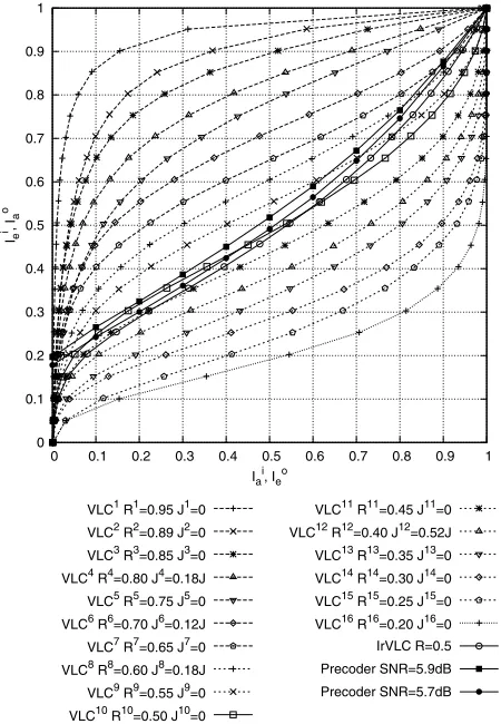
In Fig. 4 we provide the inverted EXIT curves that characterise the bit-based APP SISO VLC decoding of the above-mentioned VLC codebooks, together with the rate-1 decoder’s EXIT curves atEb/N0 values of 5.7 and 5.9 dB, assuming a jamming-free, uncorrelated Rayleigh fading channel. In all cases, EXIT curves were generated using uncorrelated Gaussian distributed a priori LLRs, based on the assumption that the transmission frame’s bits have equiprobable logical values. This is justified because we employ a long interleaver length and because the entropy of the VLC encoded bits was found to be only negligibly different from unity for all the considered VLC codebooks.
Fig. 4 also shows the inverted EXIT curve of the IrVLC scheme. This was obtained as the appropriately weighted superposition of the N = 16component VLC codebooks’ inverted EXIT curves, where
0 0.1 0.2 0.3 0.4 0.5 0.6 0.7 0.8 0.9 1
0 0.1 0.2 0.3 0.4 0.5 0.6 0.7 0.8 0.9 1
Ie i, I
a
o
Iai, Ieo
VLC1 R1=0.95 J1=0
VLC2 R2=0.89 J2=0
VLC3 R3=0.85 J3=0
VLC4 R4=0.80 J4=0.18J
VLC5 R5=0.75 J5=0
VLC6 R6=0.70 J6=0.12J
VLC7 R7=0.65 J7=0
VLC8 R8=0.60 J8=0.18J
VLC9 R9=0.55 J9=0
VLC10 R10=0.50 J10=0
VLC11 R11=0.45 J11=0
VLC12 R12=0.40 J12=0.52J
VLC13 R13=0.35 J13=0
VLC14 R14=0.30 J14=0
VLC15 R15=0.25 J15=0
VLC16 R16=0.20 J16=0
IrVLC R=0.5
Precoder SNR=5.9dB
[image:4.595.326.551.57.382.2]Precoder SNR=5.7dB
Fig. 4. Inverted VLC EXIT curves and rate-1 decoder EXIT curves, assuming an interference-free, uncorrelated Rayleigh fading channel.
the weight applied to the inverted EXIT curve of the component VLC codebook VLCn is proportional to the specific number of source symbols employed to encodeJn [1]. Using the approach of [1], the values of{Jn}Nn=1given in Fig. 4 were designed so that the IrVLC coding rate matches that of our regular VLC scheme, namely 0.5. Furthermore, we ensured that the inverted IrVLC EXIT curve did not cross the rate-1 decoder’s EXIT curve at Eb/N0 of 5.7dB. We note that only 4 of the 16 VLC components are indeed chosen by the algorithm of [1] to encode a non-zero number of source symbols. As shown in Fig. 4, the presence of the resultant open EXIT chart tunnel implies that an infinitesimally low BER may be achieved by the IrVLC-FFH-MFSK scheme forEb/N0 values above 5.7dB. By contrast, an open EXIT chart tunnel is not afforded forEb/N0values below 5.9dB in the case of the benchmarker VLC-based scheme.
Analogous to the IrVLC design of Fig. 4 created for the interference-free channel, we have also designed an IrVLC code for the Rayleigh fading channel contaminated by PBNJ, as-suming Eb/NJ = 10dB and ρ = 0.1. The values of Jn, n= 1, . . . ,16optimized for this particular jammed channel are
[0 0 0 0.24 0 0 0 0.22 0 0.03 0 0.5 0 0 0 0].
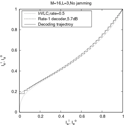
Finally, the EXIT characteristics were verified by carrying out the iterative decoding process of Fig. 1 and recording the MI values at the output of the inner and outer decoders, as seen in Fig. 5. We observe that the iterative decoding trajectory more or less follows the EXIT curves of the inner and outer IrVLC decoder, confirming the accuracy of our EXIT chart analysis.
0 0.2 0.4 0.6 0.8 1
0 0.2 0.4 0.6 0.8 1
Ie i, I
a
o
Iai, Ieo
M=16,L=3,No jamming
[image:5.595.51.261.70.277.2]IrVLC,rate=0.5 Rate-1 decoder,5.7dB Decoding trajectroy
Fig. 5. IrVLC and rate-1 decoder EXIT curves as well as decoding trajectory, assuming an interference-free, uncorrelated Rayleigh fading channel.
versus Eb/N0 results of Fig. 6, where we assumeEb/NJ = 10dB and ρ = 0.1, when the transmitted signal encounters PBNJ. We observe that as predicted by the EXIT chart of Fig. 4 the IrVLC scheme achieves an arbitrarily low BER atEb/N0 values in excess of 5.7 dB in interference-free channels and at 6.6dB in the channels contaminated by PBNJ. The corresponding Eb/N0 values for the VLC-based scheme are 5.9 and 6.9 dB. We also observe that both of the precoded systems, namely the VLC and the IrVLC-based schemes, yield superior performance compared to the system operating without the precoder. The BER improvement over the system using no precoder is achieved at the cost of an increased complexity imposed by the increased number of decoding iterations. For example, the IrVLC-based scheme requires 110 iterations to reach convergence at 6.6dB in the jammed channel. Naturally, the number of iterations can be significantly reduced by raising theEb/N0value by as little as 0.1 or 0.2dB.
10-6 10-5 10-4 10-3 10-2 10-1 100
0 2 4 6 8 10
BER
Eb/N0 (dB)
M=16,L=3,code rate=0.5,source frame length J=100000 symbols
No jamming Jammed channel VLC,without precoder VLC,with precoder IrVLC
Fig. 6. BER versus SNR performance of the VLC and IrVLC based schemes, in jammed as well as an interference-free, uncorrelated Rayleigh fading channels.Eb/NJ = 10dB andρ= 0.1are assumed in the jammed channel.
V. CONCLUSION
We have investigated the serial concatenation of IrvLC coding with a FFH-MFSK modem operating in a Rayleigh fading channel, when the transmitted signal was corrupted by PBNJ. Using EXIT chart analysis, we found that a stand-alone FFH-MFSK demodulator does not promise significant iterative gains, motivating us to employ a unity-rate precoder for the sake of making the channel to appear recursive. Furthermore, the IrVLC code was designed in such a way that the inverted EXIT curve of the IrVLC decoder matches the EXIT curve of the inner decoder. In this way, an open EXIT chart tunnel may be created even at low SNR values, providing source-correlation-dependent additional performance gain of up to 0.3dB over VLC-based scheme. In our future work, we will investigate more sophisticated three-stage iterative decoding, through exchange of extrinsic information amongst the demodulator, the rate-1 decoder and the outer decoder.
REFERENCES
[1] M. T¨uchler and J. Hagenauer, “EXIT charts of irregular codes,” in
Conference on Information Sciences and Systems, (Princeton, NJ), pp. 748–753, March 2002.
[2] R. G. Maunder, J. Wang, S. X. Ng, L.-L. Yang, and L. Hanzo, “Irregular Variable Length Coding for Near-Capacity Joint Source and Channel coding,” in (to appear) IEEE International Conference on Communications, (Glasgow, Scotland), June 2007.
[3] V. Buttigieg and P. G. Farrell, “Variable-length error-correcting codes,”
IEE Proceedings on Communications, vol. 147, pp. 211–215, August 2000.
[4] S. ten Brink, “Convergence of iterative decoding,”IEEE Transactions on Communications, vol. 49, pp. 1727 – 1737, October 2001. [5] K. C. Teh, A. C. Kot, and K. H. Li, “FFT-based clipper receiver for
fast frequency-hopping spread-spectrum system,” inProceedings of the IEEE Symposium on Circuits and Systems, vol. 4, pp. 305–308, May-June 1998.
[6] P. C. P. Liang and W. E. Stark, “Algorithm for joint decoding of turbo codes and M-ary orthogonal modulation,” inIEEE International Symposium on Information Theory, 2000, p. 191, June 2000.
[7] M. C. Valenti, E. Hueffmeier, B. Bogusch, and J. Fryer, “Towards the capacity of noncoherent orthogonal modulation: BICM-ID for turbo coded NFSK,” inIEEE Conference on Military Communications, 2004. MILCOM 2004, vol. 3, pp. 1549 – 1555, October-November 2004. [8] S. Lloyd, “Least squares quantization in PCM,”IEEE Transactions on
Information Theory, vol. 28, no. 2, pp. 129–137, 1982.
[9] U. C. Fiebig, “Soft-decision and erasure decoding in fast frequency-hopping systems with convolutional, turbo, and Reed-Solomon codes,”
IEEE Transactions on Communications, vol. 47, pp. 1646 – 1654, November 1999.
[10] J. G. Proakis,Digital communications. Singapore: Mcgraw-Hill, 2001. [11] S. Ahmed, S. X. Ng, L. L. Yang, and L. Hanzo, “Iterative Decoding and Soft Interference Cancellation in Fast Frequency Hopping Multiuser System Using Clipped Combining,” inProceedings of the IEEE Wireless Communications and Networking Conference, WCNC 2007 (CD-ROM)., March 2007.
[12] R. Y. S. Tee, S. X. Ng, and L. Hanzo, “Precoder-aided iterative detection assisted multilevel coding and three-dimensional EXIT-chart analysis,” inIEEE Wireless Communications and Networking Conference, 2006. WCNC 2006, vol. 3, pp. 1322–1326, April 2006.
[13] L. Bahl, J. Cocke, F. Jelinek, and J. Raviv, “Optimal decoding of linear codes for minimizing symbol error rate (Corresp.),”IEEE Transactions on Information Theory, vol. 20, no. 2, pp. 284–287, 1974.
[14] V. B. Balakirsky, “Joint source-channel coding with variable length codes,” inIEEE International Symposium on Information Theory, (Ulm, Germany), June 1997.
[image:5.595.52.296.519.687.2]