In Figure 164 there are two fixed size outlets in the base of the seed box. An adjustable plate with similar hole sizes is mounted below the base. It can be rotated relative to the holes in the seed box to vary the size of the outlet and hence the seeding rate. The agitator used to ensure seed does not bridge or otherwise fail to pass through the opening at a reasonably uniform rate is also clearly shown. In this case, the seed falls through the openings directly onto a spinning disc that spreads the seed over the seedbed surface in a broadcast planting pattern.
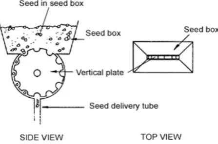
In the stationary opening type of seed meter (Figure 165) a rotating plate with varying hole sizes around its periphery is used to adjust the size of the opening in the base of the seed box.
Figure 165: A stationary opening seed meter using a rotating plate to adjust the outlet size
As in Figure 164, the seeding rate is controlled by changing the size of the outlet orifice in the base of the seed box by rotating a plate with various hole sizes around its periphery until the appropriate hole size is positioned over the box outlet.
While most stationary opening types of seed meter utilise a shaft-driven agitator, some rely on a small diameter flexible spring wire that is attached to the top of the seed box then passes through the outlet orifice far enough to make contact with the ground. As the machine moves forward the spring wire ‘jiggles’ (vibrates) and so provides a degree of agitation to the seed in the box.
For uniformity in seeding rate, the outlet orifice has to be above some minimum size (in relation to seed size) and the seed lot must exhibit a high degree of ‘flowability’. If the seeds have a tendency to pack or otherwise cling together in the seed box, flow through the orifice may be irregular, intermittent or cease completely.
While stationary opening type seed meters are still extensively used on many broadcast type planters, they have largely been replaced in drill type planters. Nevertheless, because of their simplicity and low cost they are still used for specific applications. For example, they are still commonly used in vegetable and grain crop production in many small-scale, low-resource agricultural systems.
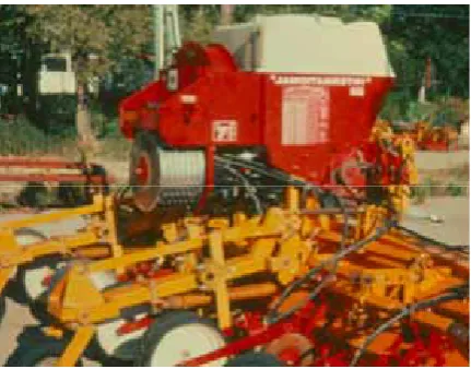
Figure 166: An example of a stationary opening type seed meter used for pasture renovation
External force feed type seed meters
External force feed seed metering systems employ a rotating member in the form of a fluted or a peg/studded roller to regulate seed flow from the seed box to the seed delivery system. In both cases, as the roller rotates the seed is moved and metered by the external surface of the roller (Figure 167).
Figure 167: General principle of operation of ‘external force feed’ seed meter types
Fluted roller types
Figure 168 shows the general form of the fluted roller type of external force feed seed meter. This type of meter essentially consists of a fluted roller, a sliding cut-off and an adjustable flap. The rotating fluted roller and the stationary cut-off are moved axially as a unit to change the exposure of the fluted roller to the seed. The adjustable flap can moved closer to, or further away from, the roller to change both the cross-section area through which seed can move and the extent the seed has to be moved by the roller before it can exit the meter.
Figure 168: The general form of the fluted roller type of external force feed seed meters
The seeding rate on the fluted roller type meter can be adjusted by one or more of the following:
• adjusting the speed of rotation of the fluted roller relative to ground speed (i.e. adjust the velocity ratio);
• sliding the shaft axially to change the length of the flutes exposed to the seed; and/or
• adjusting the flap position to accommodate different seed sizes, alter the seeding rate or, when fully opened, facilitate cleaning of the meter.
Typically on a multi-row machine, there is one meter for each row and all meters are driven from a common square shaft passing through the centre of each roller and extending across the full width of the machine.
In general:
• the speed of the shaft is adjusted by a gear box located in the drive train from a ground wheel to the shaft;
• to expose more or fewer of the fluted rollers to the seed, the common shaft is moved axially via a lever at one end of the shaft; and
• the outlet flap has to be adjusted individually on all meters.
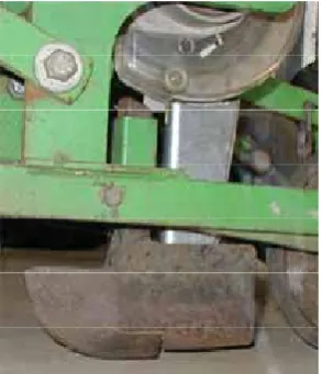
Figure 169 shows the front view of a fluted roller type of external force feed seed meter with the fluted roller moved axially so as to have no exposure to the seed.
Figure 169: Front view of a fluted roller type seed meter
Peg or studded roller types
While all external force feed meters have the same principle of operation (Figure 167), the peg or studded roller type differs from the fluted roller type in that:
• the straight-cut or the helical-cut flutes (i.e. grooves cut in the roller) that meter the seeds are replaced by raised pegs or studs (i.e. protrusions on the roller) for the same purpose; and • the roller remains in a fixed position, i.e. the roller cannot be moved axially as a method of
adjusting the seed rate.
Figure 170 shows the rear view of a peg or studded roller type of external force feed seed meter. It clearly shows the pegs or studs that replace the flutes and that the roller, while free to rotate, cannot be moved axially to change the exposure of the roller to the seed lot.
Typical methods of changing the metering rate of peg or studded roller type external force feed meters include:
• adjusting the speed of rotation of the peg or studded roller in relation to ground speed (i.e. adjusting the velocity ratio);
• adjusting the flap or base plate position to accommodate different seed sizes, altering the seeding rate or when fully opened facilitating cleaning of the meter; and
• optional methods, such as using an adjustable slide to change the size of the seed entry orifice, using inserts that essentially increase the diameter of the roller and reduce the depth of the pegs or studs, and providing optional roller types.
Typically on a multi-row machine, there is one meter for each row and all meters are driven from a common round or square shaft passing through the centre of each roller and extending across the full width of the machine. The base plate position of all meters is usually adjusted by rotating a common shaft to which all base plates are attached.
Internal force feed type seed meters
Internal force feed seed metering systems, often referred to as double run seed meters, employ a rotating member in the form of a double-sided flanged disc. The width of the flange and the size of corrugations on their internal surface differ on each side of the disc, giving what is termed a fine and coarse side of the disc. As the disc rotates seed, directed to either the fine or coarse side of the disc (hence the term double run), is moved and metered by this corrugated internal surface of the flange (Figure 171).
Figure 171: The path of seed movement through an internal force feed type seed meter
Seed is directed to either the fine or the coarse side of the meter by moving a slide or a flap inside the seed box. Typically, the coarse side is used to meter larger seed while the fine side is used to meter smaller seed. For very high seeding rates, small seed may be directed through the coarse side of the meter.
Typical methods of adjusting the seeding rate include:
• adjusting the speed of rotation of the roller in relation to ground speed (i.e. adjust the velocity ratio);
• in some particular types, adjusting an insert in the lower portion of one side of the meter housing to effectively reduce the width of the flange and hence the seeding rate.
Figure 172 shows the side view of a typical internal force feed or double run seed meter while Figure 173 shows the front view of three such meters mounted under a common seed box.
Figure 172: The side view of a typical internal force feed type seed meter
7.3.2 Precision seed metering devices
Unlike mass flow seed meters, precision meters attempt to meter single seeds. While there is a large range of precision metering devices, most can be broadly classified as ‘plate’, ‘belt’, ‘disc’, ‘drum’ or ‘finger’ types. Classification largely depends on the design and/or shape of the principle moving element that enables seed singulation (i.e. the selection of single seeds from the seed lot) (Figure 174). Nevertheless, considerable variation exists within each type and these are discussed below.
Figure 174: General types of precision seed metering devices
Plate type precision seed meters
Plate planters are taken here to be those that principally use a moving plate with indents, i.e. holes, cells or cups, around its periphery and metering performance is generally highly dependent on matching the size (length, breadth and thickness) of the indents to the size of the seed. Plate meters can be sub-classified as ‘horizontal plate’, ‘inclined plate’ or ‘vertical plate’ types (Figure 175).
Figure 175: Types of plate seed meters
Horizontal plate type precision seed meter
Figure 176 depicts the typical form of a horizontal plate meter. The plate has a number of holes or cells around its periphery and a portion of the plate is exposed to the seed. If the hole or cell is of the appropriate size, a single seed will fall into it as it passes through the segment where the plate is exposed to the seed. The plate then moves the seed to the non-exposed segment, where it is ejected or falls due to gravity into the seed delivery tube. A metal pawl at the interface between the exposed and non-exposed portions ensures that no seed other than that fully enclosed in the hole or cell passes from the seed box.
Figure 176: Side and top views of a horizontal plate meter
The seeding rate is altered by changing the velocity ratio of the plate or by changing to a plate with more or fewer holes or cells. In general, the hole or cell diameter and the plate thickness is varied to suit a particular seed size. Accurate performance depends on the use of graded seed and the selection of an appropriate plate to suit that seed size.
Figure 177 shows the top and rear view of a horizontal plate meter. The top view shows that portion of the plate exposed to the seed at the base of the seed box. It shows the cut-off pawl that ensures only the seed in the cells can exit from the seed box. The rear view shows that portion of the plate not exposed to the seed. The ejector pawl is folded back to show a cell positioned over the seed delivery tube.
Inclined plate type precision seed meter
Inclined plate meters have the same components and operating principle as the horizontal plate meter except the plate rotates in an inclined plane (Figure 178). In general, the segment of the plate exposed to the seed is smaller and because of the plate’s inclined angle the cut-off mechanism need not be so aggressive; it is often a foam roller. While the incline plate meter has limitations in common with horizontal plates (i.e. the need to have graded seed and matched cells) they cause less damage to fragile seeds due to the less aggressive singulation process.
Figure 178: Side and top views of an inclined plate seed meter
Figure 179 shows the inclined plate in the base of the seed box with and without the seed baffle plate in place. In the operating position, the baffle restricts the portion of the plate exposed to the seed. The foam cut-off pawl is shown when the baffle has been removed.
Figure 179: Views of the inclined plate with and without the seed baffle in place
Figure 180: the rear view of an inclined plate type seed meter
Where a cup-like indent is used instead of a hole in the plate to separate the seeds, there is no need for a cut-off device; any seed not partially enclosed by the cup simply falls back to the seed lot.
A limitation of the inclined plate meter is the tendency for seeds to be dislodged from the holes or cells before being deposited into the seed delivery tube, particularly when operating at higher metering rates. This is caused by excessive vibration when travelling over irregular seedbeds and/or the centrifugal force generated by higher plate speeds. The latter can be overcome by using two plates to feed one seed delivery tube. This enables the plate rotational speed to be halved for a given metering rate. Figure 181 shows a unit with two inclined plates feeding a common seed delivery tube. A baffle between the seed box and the metering chamber is used to adjust the quantity of seed exposed to the lower portion of the plates. Because the plates have a high degree of inclination there is no requirement for a cut-off device.
Figure 181: Twin inclined plate meters delivering seed to a common delivery tube
Vertical plate type precision seed meters
[image:11.595.141.450.127.254.2]Vertical plate type precision seed meters can be sub-classified as ‘mechanical’, ‘air assisted’ and ‘brush assisted’, depending on the method of singulation (Figure 182).
Figure 182: General types of vertical plate meters
[image:11.595.187.411.446.594.2]Mechanical vertical plate type precision seed meter
Figure 183 shows the typical form of a mechanical vertical disc type seed meter. As with the horizontal and inclined plate types, seeds are separated by mechanical means, i.e. dependent on matching the seed size to the size of the cells in the plate. The top of the plate is exposed to the seed and the close tolerance between the disc and the housing provides for both cut-off and the retention of seeds in the cells until deposited into the seed delivery system at the base of the meter. Typically, the metering rate is adjusted by changing the velocity ratio of the plate or by selecting a plate with more or less cells around its periphery. Seed metering performance is highly dependent on the use of graded seed and the match between the seed and cell sizes.
Figure 183: Side and top views of a typical vertical disc type seed meter
The width of the meter housing is usually fixed, so the overall width of the plate must remain constant, irrespective of the seed size. The plate is usually made up from a number of matched thinner plates of varying thickness to account for the seed size as well as the width of the plate chamber.
Figure 184: The top and side views of a vertical plate meter used for vegetable production
Air assisted vertical plate type precision seed meter
The air assisted vertical plate meter differs from other plate meters in that the plate has comparatively large, vented conical-shaped cells around its periphery and singulation is accomplished with the aid of a continuous jet of compressed air. The plate is fed externally just above its centreline and each of the cells is sufficiently large to hold a number of seeds (Figure 185). Before reaching the highest point of the plate, each cell is exposed to a jet of compressed air. This removes all but the one seed covering the vented section at the base of the inverted cone-shaped cells. The additional seeds removed from the cell simply fall back onto the surface of the seed lot. The single seed is conveyed to the outlet point at the base of the plate housing. A fixed ejector, running in the plate’s vent groove and located at the base of the housing, is often used to ensure the individual seeds are ejected from the cell.
Figure 185: A cross-sectional representation of an air assisted vertical plate meter
Nevertheless, compared to other plate meters these meters are expensive to manufacture (because of the tolerances and degree of machining required to make the plates and housings, etc) and expensive to operate (because of the power requirements, etc, associated with the blower used to provide the supply of compressed air).
Figure 186 shows the exposure of the vertical plate at the base of the seed box (the compressed air jet removed) and the shape of a typical plate used in an air assisted vertical plate meter.
Figure 186: A view of the seed box base and plate from an air assisted vertical plate seed meter
Brush assisted plate type precision seed meter
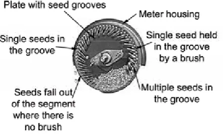
Brush assisted vertical plate seed meters have a plate with a series of seed grooves around the periphery (Figure 187). The grooves have a cross-sectional area matched to the seed size but the groove is long enough to accommodate a number of seeds. The plate is fed internally from a seed chamber at the base of the plate, where the level of seed is adjusted and maintained by the position of a choke plate. A brush ring (not shown in Figure 187) with a continuous layer of short bristles is placed on top of the plate and fixed to the housing so that the bristles extend one seed width in from the edge of the plate around the top two-thirds of the plate. As the plate turns through the segment exposed to the seed, a number of seeds fall into the groves. As it continues to move into the region of the brush only, the seed in the extremity of the groove is held in the groove by the brush; all the other seeds fall back to the seed lot.
The single seed in each groove is held by the brush until the plate moves to the discharge point where the brush terminates and allows the seed to fall into the seed delivery tube.
[image:13.595.184.410.569.705.2]Figure 188 shows a more detailed view of the brush assisted plate meter’s housing and plate. With the plate removed, the brush ring that extends about two-thirds the way around the circumference of the plate housing is visible. Further, the radially aligned outer portion of the seed groove, where the single seed is held by the brush, is visible on the enlarged view of the matching plate. The major advantages of the brush assisted vertical plate are design simplicity and the ability of the brush and groove combination to allow accurate metering without the need to use graded seed.
Figure 188: The housing and plate from a brush assisted vertical plate seed meter
Belt type precision seed meters
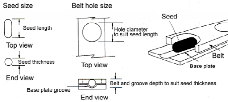
Belt type precision seed meters are similar to mechanical plate meters in the principle of operation but differ substantially in that the plate is replaced by a continuous rubberised belt of fixed width and thickness with holes, compatible to the seed size, equally spaced along its length.
As Figure 189 shows, seed falls from the seed box into the feed chamber where it is exposed to a portion of the belt. The amount or depth of seed in the chamber needs to be regulated to prevent choking or excessive wear on the mechanisms. The depth of seed required depends on the seed size and is adjusted by changing the size of the choke plate which partially covers the aperture between the seed box and the metering chamber. A stationary base plate, located under the belt along the length of the metering chamber, stops the seed falling through the belt.
[image:14.595.154.447.577.737.2]As all belts have the same thickness, a particular combination of base plate and hole size is required for each different seed size, i.e. the combination of belt hole diameter, the thickness of the belt, and the depth and width of the groove in the base plate form a particular seed cell size.
[image:15.595.114.484.375.540.2]Figure 190 shows the belt and base plate combination for a small, round seed with a thickness equal to the belt thickness (e.g. sorghum seed). Figure 191 shows the combination for a large, cylindrical seed (e.g. bean seed).
Figure 190: An example of the belt and base plate combination for a small round seed
Figure 191: An example of the belt and base plate combination for a large cylindrical seed
The repeller wheel ensures that seed other than that fully enclosed in the cell remains in the metering chamber.
The accuracy of metering depends on similar criteria to that of other mechanical plate meters, i.e. uniformity of seed size, matching of cell size to seed size, and the speed of the belt. Metering rate is adjusted by altering the speed of the belt relative to ground speed and the number of holes per unit length of the belt. Incorrect matching of the cell and seed sizes increases the potential for seed damage during the metering process.
Figure 192: Side view of a belt type precision seed meter with the side plate removed
Vacuum disc type precision seed meters
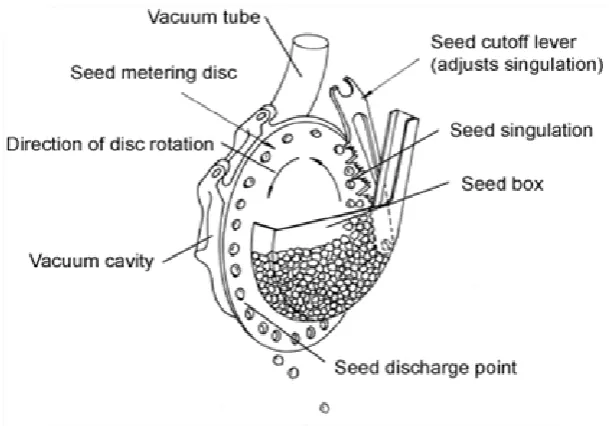
The vacuum disc precision meter is now the industry standard, even though pressurised disc metering systems have been developed. Essentially, this system consists of a seed box, a split housing, a vertical rotating disc that has a row of holes around its circumference, and a fan or blower.
The disc differs from the plate used in plate type precision meters in that the seeds do not fall into, nor pass through, the hole and disc thickness plays no part in the singulation process. Further there is no need to correctly match the seed size to the hole size, other than ensuring the hole diameter is smaller than the smallest cross sectional dimension of the seed in the seed lot, i.e. small enough to ensure that seeds cannot pass through the hole.
As Figure 193 shows, the disc rotates between the two halves of the housing and is exposed to a negative pressure (vacuum) on one side and to the seed on the other. As the disc rotates, each hole passes through the seed lot and picks up one or a number of seeds as a result of the pressure difference across the disc, i.e. seeds are held by suction to the hole. As the disc continues to rotate, the seeds attached to a hole are subjected to the effects of a wiper that can be adjusted to cover more or less of the hole diameter. If the wiper is correctly adjusted all seeds except one will be wiped from each hole and fall back under gravity to the seed lot. The single seeds are then carried by the disc towards the base of the meter where the pressure difference is removed and the seed falls into the seed delivery system. The metering performance therefore depends mainly on a combination of the following:
• ensuring the disc hole size is the minimum required to prevent the smallest seed in the seed lot passing through, or being lodged in, the holes in the disc;
• selecting the correct pressure differential across the hole;
• setting the wiper/cutoff in the correct position to achieve singulation; and
Figure 193: A diagrammatic representation of a vacuum disc type precision seed meter
The level of vacuum must be adjusted so that the pressure difference is sufficient to hold the seed to the plate but allow singulation by the cut-off wiper. Heavier seeds require a greater pressure difference. For a given seed, the smaller the hole diameter, the greater the pressure difference required. The setting of the wiper position is critical to metering performance. Incorrect setting results in either increased incidence of ‘doubles’ (two seeds per hole) or ‘misses’ (no seed per hole). Excessive disc speed reduces metering performance as it restricts the exposure time of each hole to the seed lot and increases the force required to hold the seed during the pick-up and singulation processes.
Because the seeds do not have to be precisely matched to the hole size, grading of seed is not an essential requirement, although still preferable for maximum accuracy of metering.
The seed metering rate is adjusted by changing the disc speed relative to ground speed and by selecting a disc with more or fewer holes around its circumference.
[image:17.595.145.450.79.292.2]Figure 194 shows the side view of a vacuum disc metering unit delivering seed directly to the furrow through the rear cavity of a runner type opener and a plan view of a typical vacuum metering disc. The projections on the disc help agitate the seed in the metering chamber.
Pressurised drum type precision seed meters
While vacuum drum type precision seed metering systems are commonly used in seedling nurseries to plant seeds in trays, pressurised drum metering systems are more common in field crop production.
This type of precision seed meter typically consists of a seed box, a multi-row metering drum, a seed delivery manifold and a blower or fan unit to pressurise the drum and seed box and deliver the seed to the furrow. An open-ended drum is sealed to, but free to rotate on, a fixed end plate through which air and seed are delivered into the drum and through which seed exits the drum via delivery tubes (Figure 195). The drums of most metering units of this type have four or six rows of equally spaced holes around their circumference. As with vacuum disc types, the hole has to be smaller than the seed to be metered so a drum with the appropriate number of rows and size of holes has to be selected for each size to be planted.
Figure 195: Sectional views of a pressurised drum type precision seed meter
Seed enters the drum from the seed box through a delivery chute that spreads it over the lower internal surface of the drum. As the drum rotates, one or two seeds adhere to, and are then carried by, the holes as they pass through the seed lot. Seed adhesion results from the pressure differential across the hole, i.e. the pressure inside the drum is higher than atmospheric pressure outside the drum. As the drum continues to rotate, the seeds pass a cut-off brush that causes all but one seed to remain on each hole; the excess seed falls back to the seed lot due to gravity. When the hole reaches its uppermost position, a roller positioned outside the drum blocks the hole, stopping the pressure differential, and the seed falls vertically into the seed discharge manifold.
Seeds falling into the discharge manifold enter a delivery tube where they are carried, by the air flow in the tube, to the furrow.
High metering performance relies on selecting the correct hole size and the optimum pressure setting for the particular seed type. For a given drum, the only means of adjusting the seeding rate is to change the rotational speed of the drum relative to ground speed.
[image:18.595.141.447.260.452.2]Pressurised drum type precision seed metering systems are expensive to manufacture and have limited row capacity. This, together with the developments in, and the flexibility afforded by, for example, vacuum disc metering systems, has seen a decline in their popularity since the mid-1980s.
Figure 196: A rear side view of a pressurised drum precision seed metering unit
Finger pick-up type precision seed meters
[image:19.595.191.407.80.249.2]The finger pick-up (or plateless) precision seed meter (Figure 197) was initially developed in an attempt to overcome the inconvenience of having to change the hole size and hence the plate, disc or drum every time a different seed size was to be metered.
Figure 197: A diagrammatic representation of a finger pick-up type precision seed meter
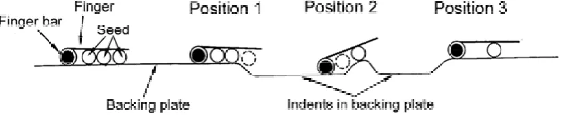
Seeds fall from the seed box to the pick-up chamber in which a number of spring-loaded, cam-operated fingers rotate in a vertical plane. As the fingers move towards the base of the chamber, the cam causes the individual finger bars to rotate so that the finger’s leading edge lifts away from the stationary backing plate. As it moves through the seed lot, the cam allows the finger to close so that it traps one or more seeds between it and the backing plate. Trapped seeds are elevated from the seed lot and pass over two indented areas on the backing plate, where singulation occurs. The single seed remaining in the finger is deposited through a hole towards the top of the backing plate into a conveying system. This maintains the seed spacing until it is deposited into the seed delivery system at the base of the meter.
[image:19.595.162.434.369.562.2]three seeds (in this case) are trapped, held and moved upwards along the backing plate until it approaches the first indent as shown in Position 1 where the first (and perhaps the second) seed is released and allowed to fall vertically downwards back to the seed lot.
Figure 198: The singulation process used on finger pick-up type precision seed meters
The seed is released because the finger position is dictated by the remaining seed or seeds. Other opportunities for singulation occur as the finger leaves the first indent and when it enters and leaves the second indent. For example, in Position 2 the finger is leaving the first indent position with two seeds under the finger. Here, there is an opportunity for the second seed to be released because the finger position is dictated by the leading seed as it reaches and is pushed up the incline. By the time the finger exits the second indent, only one seed remains under each finger as shown in Position 3.
Figure 199 shows the form of a typical finger pick-up type precision meter. A portion to the external cover has been removed to show the fingers, the indent section of the backing plate and the hole in the backing plate through which the seed is deposited to the elevator section.
Figure 199: An example of a finger pick-up type precision seed meter
Changing the speed of the fingers’ rotation relative to ground speed is the sole means of changing the seeding rate on this type of seed meter.
[image:20.595.188.407.410.598.2]7.4 Selection of seed meter type
No one seed metering system can meet the requirements of all crop types. Compromises have to be made and, in many cases, at least two planting machines will be required – one for drill planting and one for precision planting, particularly where both summer and winter cropping is undertaken.
Irrespective of the cropping program, an informed decision can only be made if the following information is known for each of the crops to be planted:
• the established population required and the expected levels of both germination and field emergence;
• the range of agronomically acceptable row spacings;
• the sensitivity of crop yield to the evenness of plant spacing along the row; and
• the physical properties of the seed: seed size and variation in seed size, seed shape and seed fragility in particular.
SECTION 8
Planter seed delivery components
Seed delivery systems include those devices that convey the seed from the meter to the device that deposits the seed on the soil surface or in the furrow.
8.1 Functional requirements of seed delivery systems
The essential functional requirements of seed delivery systems are to:
• convey the seed from the seed meter discharge point to the seed placement device: • maintain metering accuracy (seed spacing) during seed conveyance; and
• enable the seed to be deposited on the soil surface or in the furrow in an appropriate manner in terms of both seed placement within the furrow and seed spacing along the row.
8.2 Operational requirements of seed delivery systems
To meet their functional requirements, the operational requirements of seed delivery systems differ somewhat, depending on the type of seed metering system used.
On drill planters, where mass flow seed metering systems are typically used, the design of the seed delivery system has little influence on the overall outcome, provided seed flow through the system is not unduly impeded and that the exit velocity is low enough to ensure seeds are placed on the furrow base rather than adjacent to, or on the side walls of, the furrow because the seed has bounced or otherwise been displaced when it came in contact with the soil.
On precision planters, the design of the delivery system is particularly important because a functional requirement is to translate seed metering accuracy (i.e. the uniformity in the time interval between individual seeds metered) to placement accuracy (i.e. the uniformity of seed spacing along the furrow or row). To achieve this, the typical operational requirements of the delivery tube, where used, are that they:
• are as short, straight and rigid as possible; • have the smallest adequate cross-sectional area; • have a smooth interior surface; and
• terminate, where possible, with a rearward deflection.
While the reasons for having short, straight, rigid delivery tubes with a smooth interior and appropriate cross section are obvious, the reason for having the tube terminate with a rearward deflection is often not understood. To prevent seeds bouncing or rolling on contact with the soil, their true exit velocity should, ideally, be small and vertical, i.e. having a zero component in the direction of machine travel. This can only be achieved if the seeds leave the delivery system with a rearward velocity similar to the forward velocity of the machine.
8.3 Types of seed delivery systems
Most delivery systems can be broadly classified as: • gravity drop;
• mechanical assist; or • pneumatic.
8.3.1 Gravity drop seed delivery systems
[image:24.595.208.394.284.436.2]In a gravity drop delivery system, the seed simply falls through a cavity or a tube from the seed meter to the soil. Where precision metering systems are used and soil surface residue conditions permit, the seed meter is usually placed as close as possible to the soil surface to reduce the length of the delivery tube required. Figure 200 shows a vacuum disc seed metering system close coupled with a runner type furrow opener. The seed falls through the split cavity of the runner opener to the base of the furrow.
[image:24.595.225.372.520.691.2]Figure 200: Seed delivery by gravity drop through the rear, split cavity of a runner opener
Figure 201 shows a gravity drop seed delivery system using a short dropper tube to convey the seed from a vacuum disc seed metering system to the furrow via the split cavity at the rear of a small runner type furrow opener.
Figure 202 shows a gravity drop seed delivery system using a long, rigid, dropper tube with a rearward deflection to convey seed from a precision meter to a single disc type furrow opener.
Figure 202: Seed delivery by gravity drop through a tube terminating with a rearward deflection
Where gravity drop seed delivery systems are used in conjunction with mass flow seed metering systems, the length and shape of the dropper tube is less important, provided seed flow is not unduly impeded. Figure 203 shows the typical gravity drop delivery system used on drill planters to convey seed from a mass flow type meter to the furrow.
Figure 203: Seed delivery by gravity drop through long dropper tubes on drill type planters
8.3.2 Mechanically assisted seed delivery systems
Mechanically assisted seed delivery systems incorporate a mechanical device to assist in the delivery of seed from the seed meter to the seedbed. Typically, they can be categorised as either:
• spinning discs or oscillating spout types, as commonly used on broadcast planters to assist spread seed over an appropriate width of the seedbed surface; or
While these systems remain an integral component on most broadcast planters, they are now rarely used on precision type planters. This is primarily because improvements in plant breeding, seed harvesting and seed storage have reduced the need for hill drop and check row planting patterns where mechanical delivery systems often played an important role.
[image:26.595.168.431.246.412.2]Spinning disc type
Figure 204 shows a broadcast type planter incorporating a spinning disc type system of mechanically assisted seed delivery. The disc has a number of fixed vanes radiating from its central portion. Seed falls from a stationary opening type seed meter directly onto the spinning disc. It is then spread out, or broadcast, over a given width of the seedbed surface.
Figure 204: Spinning disc type mechanically assisted seed delivery system
[image:26.595.189.405.561.754.2]Oscillating spout type
Figure 205 shows a broadcast planter with an oscillating spout type mechanical assisted delivery system. The seed is metered by a stationary opening type mass flow seed meter directly into the entry of the oscillating spout. As the spout oscillates backwards and forwards at speed, the seed is accelerated towards the discharge end of the spout and broadcast over the seedbed surface in an arc. The width of the arc can be adjusted by altering the extent to which the spout can travel in one oscillation.
The seeding rate is not uniform over the full width resulting from a single pass of a planter using a spinning disc or oscillating spout type delivery system. In general, the rate is higher in the central portion and tapers to zero at the extremity of the arc. Overlapping the arcs in subsequent passes provides for a more uniform planting rate over the entire seedbed surface.
[image:27.595.205.393.239.483.2]Conveyor type
Figure 206 shows a mechanical delivery system incorporating a seed conveyor enclosed in the furrow opener standard. The conveyor maintains seed spacing as the seed is mechanically conveyed from the horizontal plate type precision meter to the furrow opener (not shown).
Figure 206: An example of a conveyor type mechanically assisted delivery system
Conveyor type mechanically assisted delivery systems are rarely used today because of their cost and complexity and a general improvement in gravity drop delivery systems. Nevertheless, a similar concept is still used on, for example, finger pick-up type precision seed meters to maintain seed spacing from the point of discharge from the seed meter to the base of the seed metering mechanism (Figure 197).
8.3.3 Pneumatic seed distribution and/or delivery systems
Pneumatic seed delivery systems are typically used on multi-row planters fitted with a single centrally located seed box. The seed is metered into a delivery tube where it is conveyed by an air stream to individual furrow openers that are uniformly spaced across the full width of the machine. Pneumatic seed delivery systems can be sub-classified into two general types:
Pneumatic ‘delivery only’ systems
In ‘delivery only’ systems the seed is metered directly into the tube that delivers it to the furrow by air flow in the tube. In Figure 196, a drum type seed metering system feeds seeds into individual tubes that convey the seeds to their respective furrow opener. Figure 207 shows the essential components of the more typical arrangement, where each meter, positioned under a common, centrally located seed box, delivers seed to a tube that pneumatically conveys it to the furrow opener. In this case, the blower has a four-way manifold that supplies air to four individual tubes. Individual seed meters are assigned to each tube and each tube delivers seed directly to the opener.
Figure 207: The components of a ‘delivery only’ type of pneumatic seed delivery system
Pneumatic ‘delivery and division’ systems
Pneumatic delivery and division systems form the basis of the so-called ‘air seeders’ which are available as discrete machines or as a planting attachment for tined tillage equipment, such as chisel ploughs, scarifiers and cultivators.
[image:28.595.213.385.208.422.2]There is considerable variation in design, but seed for all or a number of furrow openers (typically three to nine) is metered into a single tube where it is conveyed pneumatically to a ‘dividing head’. The dividing head divides the airstream (and hence the seed) equally into a number of outlets located symmetrically around the head, each outlet delivering seed directly to an opener or a secondary head where the process is duplicated.
Figure 208: A pneumatic delivery and division system utilising primary heads only
[image:29.595.173.445.76.345.2]The system shown in Figure 208 consists of a single seed box with three mass flow type seed meters located under the box. Each seed meter delivers seed to an airstream that is subsequently divided by a four outlet primary head, each outlet delivering seed to four individual furrow openers. Typically, using a primary head only, a single seed meter can supply up to nine openers.
Figure 209 shows a system utilising both primary and secondary dividing heads.
The system in Figure 209 consists of a single, large seed box supplying seed to a single, high volume mass flow type of seed meter. This meter delivers seed to an airstream that is subsequently divided by both primary and secondary heads such that the single meter delivers seed to a total of 16 individual openers. Typically, using this system of primary and secondary heads a single seed meter can supply up to 81 individual furrow openers.
[image:30.595.219.380.221.388.2]A large range of dividing heads is available for use in pneumatic delivery and division systems. The diversity in designs precludes detailed discussion on the types and their relative operational and performance characteristics. They can range from simple cast or moulded types without any moving elements (Figure 210) to complex, fabricated systems incorporating driven components (Figure 211).
Figure 210: A simple moulded plastic dividing head
Figure 211: Seed and fertiliser heads incorporating hydraulically driven components
[image:30.595.188.407.421.657.2]All planters using pneumatic delivery and/or division systems require a way to isolate the seed meter from the effects of pressure in the airstream because any air flowing back through the meter can seriously impair metering performance. There are three general systems of loading the air stream with seed (and/or fertiliser) (Figure 212):
• the pressurised box system; • the venturi system; or
[image:31.595.117.458.136.325.2]• the air lock or rotary valve system.
Figure 212: Common methods used to load the airstream
In the pressurised box system, a hose or pipe from the fan outlet is connected to the seedbox. If the seed box is sealed, then the pressure inside the box is equal to that in the seed delivery pipe. With equal pressure above and below the seed meter, seed falls by gravity into the delivery airstream and there is no blowback through the meter to impair its performance. While the lids, etc, on the seed box need to be fully sealed when the machine is operating, the system is relatively simple and requires no additional moving parts. Any air leak in the seed box may, however, allow a pressure difference to develop and impair metering performance.
The venturi system is simple in design and trouble-free in operation. As the air enters the tapered section on the upstream side, the air velocity is increased, causing a pressure reduction to the extent there is no back pressure and the seed falls freely under gravity into the airstream. The seed box does not have to be sealed and no additional moving parts are required.
The rotary valve or air-lock system isolates the meter from the pressurised airstream in the delivery tube and discharges the seed into the airstream as it rotates. The rotary valve has to be of an adequate size to cope with the volume of seed to be metered and its sealing surfaces have to be well maintained to ensure effective operation. One disadvantage of this system is the need for additional moving parts.
While the air flow rate needs to be adequate to reliably convey the seed to the furrow opener, rates in excess of those required for delivery should be avoided. Higher rates increase seed velocity in the delivery tubes and can cause the seed to bounce or otherwise be displaced from the base of the seed furrow. Some air planters have a diffuser or expansion chamber close to the seed placement device to reduce seed velocity immediately before the seed is placed in the furrow.
Figure 213 shows the typical layout of a cultivator-based planter using a pneumatic seed delivery and division system incorporating both primary and secondary heads. A single seed meter supplies seed to a five-outlet primary head. Each outlet from the primary head is directed into an eight-outlet secondary head. Each outlet from a secondary head supplies one furrow opener. Using this system the single seed meter supplies 40 individual furrow openers.
Figure 213: An example of a pneumatic seed delivery and division system
SECTION 9
Examples of planter description
Having classified a planter (using the process set out in Section 3) it may be more fully described by providing, where appropriate/applicable, detail of its:
• soil-engaging components (i.e. soil and residue cutting device; row preparation device; furrow opener; seed firming device; seed covering device; row specific seed firming device and non row specific seed firming/levelling device);
• furrow opener depth control mechanism (i.e. frame section gauging or types within individual row gauging systems);
• seed metering (i.e. specific types within mass flow or precision metering systems); and • seed delivery and/or division system (i.e. types within gravity drop, mechanical assisted or
9.1 Example 1 – A broadcast planter
Figure 214: A broadcast planter
The planter in Figure 214 has been previously classified as a hand-held, human-powered broadcast planter.
This planter has no soil-engaging or depth control components. Nevertheless, it does have a sliding plate stationary opening type seed meter and a spinning disc type seed distribution system.
Therefore, the planter could be classified and fully described as a hand-held, human-powered broadcast planter equipped with the following components:
9.2 Example 2 – A drill planter
Figure 215: A drill planter
The drill planter in Figure 215 can be classified and fully described as a 40-row, trailed, tractor-powered drill planter equipped with the following components:
• a duckfoot dual purpose tine type furrow opening device;
• a flexible type frame section gauging furrow opener depth control device;
• a fluted roller external force feed type mass flow seed metering device; and
9.3 Example 3 – A precision planter
Figure 216: A precision planter
The precision planter in Figure 216 can be classified and fully described as a 6-row (not shown), rear-mounted, tractor-powered precision planter equipped with the following components:
• aligned double finger wheel type row preparation device;
• aligned twin inclined double disc coulter type furrow opening device;
• aligned twin inclined press wheel type row specific seedbed firming device; • dedicated gauge wheel, parallelogram type furrow opener depth control device;
9.4 Example 4 – A dibble planter
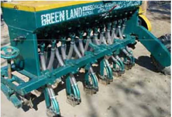
Figure 217: A dibble planter
The dibble planter in Figure 217 can be classified and fully described as an 8-row, rear-mounted, tractor-powered dibble planter equipped with the following components:
• a punch type furrow opening device;
• a rigid frame section gauging type furrow opener depth control device; • a fluted roller external force feed type mass flow seed metering device; and
SECTION 10
Planter classification and
description keys
Used in combination the keys that follow allow for the broad classification and detailed description of planting machinery in a consistent and meaningful way. The keys are derived from the information contained in the preceding sections. In both keys the classification or description is formulated by reading from right to left, i.e.:
• number of rows, mounting option, mounting, power source then type, in the case of classification; and
• options, type, then device, in the case of description.
A key for planter classification
Type of Planter Power Source Mounting Mounting Options
Number of Rows
Hand held
Hand pushed Human
Hand pulled
Animal Pulled
Trailed
Semi mounted
Rear
Mid Broadcast
or Drill or
Precision or
Dibble
Tractor
Mounted
Front
A key for planter description
Component Device
Type
Options
Plain
Notched
Bubble
Ripple
Fluted
Wavee
Soil and
Residue
Cutting Device
Disc Coulter
Turbo
Blade
Single
Aligned
Finger Wheel
Double
Staggered
Plain
Single
Notched
Aligned
Plain
Staggered
Aligned
Concave Disc
Double
Notched
Staggered
Single Finger
Finger Harrow
Multiple Finger
Sweep
Tine
Point
Roller
Soil Engaging Components
Row
Preparation
Device
Horizontal
Disc
A key for planter description (continued)
Group Device
Type
Options
Full
Runner
Stub
Concave Disc
Aligned
Single Angle
Single
Compound Angle
Aligned
Twin Inclined
Staggered
Aligned
Double
One Vertical, One
inclined
Staggered
Disc Coulter
Triple
Point
Blade
Inverted “T”
Near Vertical
Forward Curved
Dedicated
Shoe
Rearward
Curved
Point
Duckfoot
Tine
Dual Purpose
Sweep
Bioblade
Powered
Soil Engaging Components (Continued)
Furrow Opening
Device
Punch
A key for planter description (continued)
Group Device
Type
Options
Slide
Seed Firming
Device
Wheel
Loop
Trailing
Chain
With bar
Single
Concave Disc
Double
Single
Disc Coulter
Double
Single
Knife
Double
Single
Paddle
Double
Single
Tine
Double
Single
Finger
Double
Single
Soil Engaging Components (Continued)
Seed Covering
Device
Finger wheel
Double
A key for planter description (continued)
Group Device
Type
Options
Flat
Wedge
Over-Centre
Ribbed
Plain
Ribbed
Zero-Pressure
Split packer
Single
Aligned
Presswheel
Inclined
Twin
Staggered
Single
Aligned
Finger wheel
Double
Staggered
Row Specific
Seed Bed
Firming Device
Coil press
Wooden
Metal
Roller
Tyre
Spiral
Cage Roller
Toothed
Packer
Disc
Peg
Leaf
Chain
Rigid
Soil Engaging Components (Continued)
Non Specific
Seed Bed
Firming /
Levelling
Device
Harrow
Rotary
Flexible
A key for planter description (continued)
Group Device
Type
Options
Rigid Frame
Frame Section
Gauging Furrow
Opener Depth
Control Device
Flexible Frame
Rear Wheel
Dedicated Wheel
Front Wheel
Parallelogram
Twin Wheels
Rear Wheel
Dedicated Wheel
Furrow Opener Depth
Control
Individual Row
Gauging Furrow
Opener Depth
Control Device
Trailing Arm
Twin Wheels
Sliding Plate
Stationary Opening
Rotary Plate
Internal Force Feed
Fluted Roller
Mass Flow
Seed Metering
Device
External Force Feed
Peg/Studded
Roller
Mechanical Horizontal
Mechanical Inclined
Mechanical Vertical
Air Assisted Vertical
Plate
Brush Assisted Vertical
Belt
Vacuum Disc
Pressurized Drum
Seed Metering Devices
Precision Seed
Metering Device
Finger Pickup
A key for planter description (continued)
Group Device
Type
Options
No Tube
Metal Tube
Plastic tube
Gravity Drop
Seed delivery
Device
Rubber tube
Spinning Disc
Oscillating Spout
Mechanically
Assisted Seed
Delivery Device
Elevator
Delivery Only
Primary Head
Seed Delivery
Pneumatic Seed
Delivery Device
Delivery and Division
SECTION 11
Conclusion
This book attempts to describe and define terminology for all components of the wide range of planting equipment seen by the authors over many years experience, primarily in Australia, but also in China, the United States and Europe. It also includes a small number of units known only from reports in the literature. It attempts compatibility where possible with existing, related ‘standard’ information, such as that provided in the various standard documents by ASAE (2005).
SECTION 12
Further information
http://www.wantfa.com.au/ Western Australian No-tillage Farmers
Association
http://www.santfa.com.au/ South Australian No-till Farmers
Association
http://www.vicnotill.com.au/ Victorian No-till Farmers Association
http://www.cfi.org.au/ Conservation Farmers Inc
http://www.ifao.com/Notillbook/notillbooklist.htm List of books on conservation tillage / no-till / direct seeding / zero-tillage
http://www.grdc.com.au/growers/gc/gc58/notill.htm Grains Research and Development
Corporation article
http://www.istro.org International Soil Tillage Research
Organisation
http://www.ctfsolutions.com.au Controlled Traffic Farming website
http://www.fao.org/ag/ags/aGSE/agse_e/general/CONT1.htm FAO conservation agriculture
background
SECTION 13
Bibliography
ASAE (2005). Manual of Standards, Engineering Practices and Data. American Society of Agricultural Engineers, St Joseph.
Abernathy, G. H. and J. G. Porterfield (1969). Effect of planter opener shape on furrow characteristics. Trans. ASAE., 1:16–19.
Adam, N. M., McDonald M. B. and P. R. Henderlong (1989). The influence of seed position, planting and harvesting dates on soybean seed quality. Seed Sci. & Technol., 17:143–152.
Agness, J. B. and H. J. Luth (1975). Planter evaluation techniques. ASAE Paper No., 75–1003. Am. Soc. Agr. Eng., St Joseph, MI.
Asher, C. J. (1987). Crop nutrition during the establishment phase: role of seed reserves. In: I. M. Wood, W. H. Hazard and F. R. From (Editors), Crop Establishment Problems in Queensland: Recognition, Research and Resolutions. Occas. Publ. No., 34, Australian Institute of Agricultural Science, Brisbane, Qld.: 88–106.
Awadhwal, N. K. and G. E. Thierstein (1985). Soil crusts and its impact on crop establishment: A review. Soil & Tillage Res., 5: 289–302.
Baker, C. J. (1976). Experiments relating to techniques for direct drilling of seeds into untilled dead turf. J. Agric. Engng. Res. 21:133–144.
Baker, C. J. (1977). Testing and development of direct-drilling equipment for dry soils. Proc. International Conf. on Energy Conservation Crop Production, Massey University, New Zealand, 205–213.
Baker, C. J. (1993). Zero-tillage gets the go-ahead. Farming Ahead (17):15,17.
Benjamin, L. R. (1990). Variation in time of seedling emergence within populations: A feature that determines individual growth and development. Adv. in Agron. 44:1–25
Bewley, J. D. and M. Black (1982). Physiology and biochemistry of seeds in relation to germination. Vol. 2. Springer-Verlag: Berlin.
Blacket, D S. (1987). Improving crop emergence with management and agronomy. In: I. M. Wood, W. H. Hazard and F. R. From (Editors), Crop Establishment Problems in Queensland: Recognition, Research and Resolutions. Occas. Publ. No. 34, Australian Institute of Agricultural Science, Brisbane, Qld.: 192–207.
Bligh, K. and A. Stone (1993). Cross Slot shows its worth. Farming Ahead, 21:18
Braunack, M. V. and A. R. Dexter (1989). Soil aggregation in the seedbed: a Review. 2. Effect of aggregate sizes on plant growth. Soil & Tillage Res. 14: 281–298.
Brennan, P. S. and R. J. Henry (1987). Breeding strategies for the amelioration of crop establishment problems. In: I. M. Wood, W. H. Hazard and F. R. From (Editors), Crop Establishment Problems in Queensland: Recognition, Research and Resolutions. Occas. Publ. No. 34, Australian Institute of Agricultural Science, Brisbane, Qld.: 107– 119.
Brocklehurst, P. A. (1985). Factors affecting seed quality in vegetable crops. Scientific Horticulture, 36: 48–57.
Brown, N. J. (1970). The influence of cultivation on soil properties. J. Ins. Ag. Eng., 25, (3): 112–114.
Bucher, D. H., Hitzhusen, T. E. and D. T. Sorlie (1975). John Deere power-till seeder. ASAE Paper No., 75–1591. Am. Soc. Agr. Eng., St Joseph, MI.
Campbell, A. J. and C. J. Baker (1989). An x-ray technique for determining three-dimensional seed placement in soils. Trans. ASAE., 32, (2):379–384.
Cannell, R. Q. and M. B. Jackson (1981). Alleviating aeration stresses. In: G. F. Arkin (Editor), Modifying the Root Environment to Reduce Crop Stress, ASAE. Mon. No 4., Am. Soc. Ag. Eng., St Joseph. Mich: 141–192.
Carter, O. (1969). Effect of fertilisers on germination and establishment of pastures and fodder crops. Wool Tech. & sheep Breeding, July 1969,69–75.
Choi, C. H. and D. C. Erbach (1986). Cornstalk residue shearing by rolling coulters. Trans. ASAE., 26, (6): 1530–1535.
Choudhary, M. A., Gou Pei Yu, and C. J. Baker (1985). Seed placement effects on seedling establishment in direct-drilled fields. Soil & Tillage Research, 6:79–93.
Choudhary, M. A. (1988). Modelling of crop seedling emergence as a function of soil moisture and direct drilling openers. Proceedings of 11th International ISTRO Conference on Tillage and Traffic in Crop Production, Edinbrough 11–15th July 1988.
Choudhary, M. A. and C. J. Baker (1993). Conservation tillage and seeding systems in the South Pacific. Soil & Tillage Research, 27:283–302.
Collis-George, N. (1987). Effects of soil physical factors on imbibition, germination, root elongation and shoot development. In: I. M. Wood, W. H. Hazard and F. R. From (Editors), Crop Establishment Problems in Queensland: Recognition, Research and Resolutions. Occas. Publ. No. 34, Australian Institute of Agricultural Science, Brisbane, Qld.: 23–41.
Cook, S. J. and J. M. Scott (1987). Fertiliser placement strategies for establishment and growth of crops. In: I. M. Wood, W. H. Hazard and F. R. From (Editors), Crop Establishment Problems in Queensland: Recognition, Research and Resolutions. Occas. Publ. No. 34, Australian Institute of Agricultural Science, Brisbane, Qld.: 166– 172.
Cook, S. J., Clem R. L., MacLeod N. D. and P. A. Walsh (1993). Tropical Pasture Establishment. 7. Sowing methods for pasture establishment in northern Australia. Tropical Grasslands, 27: 261–275.
Elliott, L. F., McCalla T. M. and A. Waiss (1978). Phytotoxicity associated with residue management. In Crop Residue Management. W. R. Oschwald (Editor), ASA Special Publ. No 31 Am. Soc. of Agron., Madison, Wisc., 131–146.
Fenner, M. (1992). Environmental influences on seed size and composition. Hort. Rev. 13, 183–213.
Ferraris, R. (1992). Seedbed factors affecting establishment of summer crops in a vertisol. Soil & Tillage Research, 23, 1–25.
Gebresenbet, G. and H. Jonnson (1992). Performance of seed drill coulters in relation to speed, depth and rake angles. J. Agric. Engng. Res. 52, 121–145.
Gramshaw, G. M., McKeon G. M. and Clem R. L. (1993). Tropical Pasture Establishment. 1. A systems perspective of establishment illustrated by oversowing in the sub-tropics. Tropical Grasslands, 27: 261–275.
Gray, D. (1981). Fluid drilling of vegetable seeds. Hort. Rev. 3,1–27.
Gray, A. G. and D. MacIntyre (1983a). Studies of soil penetration by disc coulters of direct drills. SIAE Departmental Note No. SIN/361, Feb., 1983.
Gray, A. G. and D. MacIntyre (1983b). Soil penetration by disc coulters of direct drills. The Agricultural Engineer, 38(4):106–109.
Grevis-James, I. W. and T. R. Kamel (1977). Conservation tillage: A glossary of selected terms. QDPI, Division of Land Utilisation, Tech. Bulletin No. 32/1977. Brisbane, Australia.
Hadas, A. and D. Russo (1974). Water uptake by seeds as affected by water stress, capillary conductivity and seed-soil water contact. 2. Analysis of experimental data. Agron. J. 66:647–652.
Halderson, J. L. (1983). Planter selection accuracy for edible beans. Trans ASAE, 26, (2):367–371.
Harty, R. L., Heslehurst M. R. and J. McDonald (1987). Seed vigour. In: I. M. Wood, W. H. Hazard and F. R. From (Editors), Crop Establishment Problems in Queensland: Recognition, Research and Resolutions. Occas. Publ. No. 34, Australian Institute of Agricultural Science, Brisbane, Qld.: 79–86.
Hayes, W. A. (1985). Conservation tillage systems and equipment requirements. In: Systems Approach to Conservation Tillage. F. M. D'Itri (Editor) Lewis Pub., 21–40.
Heinonen, R. (1985). 'Soil management and crop water supply'. (4th Edition), Dept. Soil Sc. Swedish University of Agricultural Sciences, Uppsala, Sweden.
Heslehurst, M. R. and J McDonald (1987). Seed quality components of successful field establishment. In: I. M. Wood, W. H. Hazard and F. R. From (Editors), Crop Establishment Problems in Queensland: Recognition, Research and Resolutions. Occas. Publ. No. 34, Australian Institute of Agricultural Science, Brisbane, Qld.: 141–153.
Heyns, A. J. (1989). Techniques for the evaluation of precision planters. In Land and Water Use, Dodd & Grace (Editors). Balkema, Rotterdam.
Hill, J. (1986). 'V' press wheels for light soil. Agfact E4.5, 1986. Dept. Ag. NSW. Aust.
Holzhei, D. E. and T. H. Burkhardt (1985). Modelling the seed zone in the soil. ASAE paper No., 85–2020. Am. Soc. Agr. Eng., St Joseph, MI.
Janke, J. and D. C. Erbach (1985). Seed depth distribution in no till and strip till. ASAE Paper No., 85–1013. Am. Soc. Agr. Eng., St Joseph, MI.
Jorgenson, M. E. (1988). Choosing the right seeding and fertilising equipment. PAMI Gleanings, No 558, March, 1988.
Khan, A. A. (1992). Preplant physiological seed conditioning. Hort. Rev. 13: 131–181.
Kushwaha, R. L., Vaishanv, A. S. and G. C. Zoerb (1986). Soil-bin evaluation of disc coulters under no-till crop residue conditions. Trans. ASAE., 29(1):40–44.
Lock, D. S. (1993). Tropical Pasture Establishment. 5. Improved handling of chaffy grass seeds: options, opportunities and value. Tropical Grasslands, 27: 314–326.
MacLeod, N. D., Walsh P. A., Cook S. J. and R. L. Clem (1993). Tropical Pasture Establishment. 16. Economic considerations for pasture establishment. Tropical Grasslands, 27: 396–405.
Maiti, R. K., and M. De J. Carrillo-Gutierrez (1989). Effect of planting depth on seedling emergence and vigour in sorghum. Seed Sci. & Technol., 17: 83–90.
Martin, R. J. and W. L. Felton (1983). No-tillage crop production in northern N.S.W. Proceedings of the project team meeting, Agricultural Research Centre, Tamworth, May, 4th 1983).
McGahan, E. J. and B. G. Robotham (1992). Effect of planting depth on yield in cereals. Proc. Conf. on Agric. Eng., Albury. I. E. Aust. Nat. Conf. Publ. No. 92/11:121–126.
McLeod, J. G., Dyck, F B., Campbell, C. A. and C. L. Vera (1992) Evaluation of four zero-tillage drills equipped with different row openers for seeding winter wheat in the semi-arid prairies. Soil & Tillage Research, 25: 1–16.
Mead, J. A., Palmer, A. L. and K. Y. Chan (1992) Effect of seedbed condition on sowing point performance. Soil & Tillage Research, 22: 13–25.
Miller, C. P., Taylor J. A. and M. F. Quirk (1993) Tropical Pasture Establishment. 8. Management of establishing pastures. Tropical Grasslands, 27: 344–348.
Moller, N. (1975). Conventional coulters for small grain drilling. Institutionen for Arbetsmetodik Och Teknik. Report No. 28/1975.
Morrison, J. E. and C. F. Abrams (1978). Conservation tillage opener for planters and transplanters. Trans. ASAE, 21, (1):843–847.
Morrison, J. E. (1978). No-tillage experimental planter performance and depth regulation evaluation. Trans. ASAE, 21(4):602–604,609.
Morrison, J. E. and T. J. Gerik (1985). Planter depth control: 2. Empirical testing and plant responses. Trans. ASAE, 28, (6): 1744–1748).
Morrison, J E. (1988). Computerised selection of planters and drills: an example of the use of ‘AI’ in agriculture. Proceedings of 11th International ISTRO Conference on Tillage and Traffic in Crop Production, Edinbrough 11– 15th July 1988, Vol 2: 775–780.
Murray, D. H. A., Dodman R. L. and J. M. Marley (1987) Biotic factors in field crop establishment in Queensland with particular reference to insects, diseases and weeds. In: I. M. Wood, W. H. Hazard and F. R. From (Editors), Crop Establishment Problems in Queensland: Recognition, Research and Resolutions. Occas. Publ. No. 34, Australian Institute of Agricultural Science, Brisbane, Qld., 23–41.
Norman, M., Schirmer, I. and N. H. Hancock (1992). The development of electronic moisture tracking for automatic depth control of planting depth. Proc. Conf. on Agric. Eng., Albury. I. E. Aust. Nat. Conf. Publ. No. 92/11:115– 119.
Norris, C. P. (1978). Comparative testing of seed metering and seed delivery equipment. Proc. Conf. on Agric. Eng., Toowoomba. I.E. Aust. Nat Conf. Publ. 78/8:3–6.
Norris, C. P. (1982). Performance of some different types of peanut/maize planters in NQ. Proc. Conf. on Agric. Eng., Armidale. I.E. Aust. Nat. Conf. Publ. No 82/8: 149–154.
Norris, C. P., and I. A. Ryan (1993). Sunflower seeding equipment-The effect of field emergence on plant spacing accuracy. Qld Agric. J. 109:331–335.
Palmer, A. L., Smith P. A. and N. A. Albert (1988). The trouble with seeders. Proc. Conf. on Agric. Eng., Hawkesbury. I.E. Aust. Nat. Conf. Publ. No 88/12:61–63.
Payton, D. M., Hyde, G. M. and J. B. Simpson (1985). Equipment and methods for no-tillage wheat planting. Trans. ASAE. 28, (5):1419–1423.
Radford, B. J. (1982). Establishment problems in summer and winter grain crops in Queensland and possible solutions. Proceedings QDPI Crop Establishment Workshop Toowoomba, May 1982.
Radford, B. J. and R. G. H. Nielsen (1983a). Extension of crop sowing time during dry weather by means of stubble mulching and water injection. Aust. J. Exp. Agri. Anim. Husb., 23: 302–308.
Radford, B. J. (1983b). Seed soaking. Agdex No 102/23., F195/Oct 83. QDPI., Brisbane, Aust.
Radford, B. J. and R. G .H. Nielsen (1985). Comparison of a press wheel, seed soaking and water injection as aids to sorghum and sunflower establishment in Queensland. Aust. J. Exp. Agric., 25: 656–664.
Radford, B. J. (1986). Effect of press wheel and depth of sowing on establishment of semi-dwarf and tall wheats. Aust. J. Exp. Agric., 26: 697–702.
Radford, B. J. (1987). Crop establishment ailments – diagnosis and prevention. In: I. M. Wood, W. H. Hazard and F. R. From (Editors), Crop Establishment Problems in Queensland: Recognition, Research and Resolutions. Occas. Publ. No. 34, Australian Institute of Agricultural Science, Brisbane, Qld., 120–129.
Rainbow, R. W., Slattery, M. G. and C. P. Norris (1992). Effects of seeder design specification on emergence and early growth of wheat. Proc. Conf. on Agric. Eng., Albury. I. E. Aust. Nat. Conf. Publ. No. 92/11:13–20.
Riethmuller, G. P. (1990). Machinery for improved crop establishment in Western Australia. Proc. Conf. on Agric. Eng., Toowoomba. I.E. Aust. Nat. Conf. Publ. No 90/13:40–45.
Roberts, E. H. and M. Black (1989). Seed quality. Seed Sci. & Technol., 17: 175–185.
Rogers, R. B. and S. Dubetz (1979). Effect of soil-seed contact on seed imbibition. Can. Agr. Eng., 22, (1):89–92
Saxton, K. E., (1990). Criteria for conservation tillage drills and the cross-slot opener. Proceedings of the Zero-Tillage Workshop, Bismark, N. Dakota Jan.l7–19, 1990:69–74.
Schaaf, D. E., Hann, S. A. and C. W. Lindwall (1981). Performance evaluation on furrow openers cutting coulters and press wheels for seed drills. In: Crop Production with Conservation in the 80's. ASAE Publ. No. 7/81: 76–84.
Scott, J. M., (1989). Seed coatings and treatments and their effects on plant establishment. Adv. Agron., 42: 43–83.
Slattery, M. G. and R. W. Rainbow (1992). Development of a seed placement test rig. Proc. Conf. on Agric. Eng., Albury. I. E. Aust. Nat. Conf. Publ. No. 92/11:365.
Smith, E. M., Hammett, D. E. and H. J. Thompson (1979). Ground driven power tillage. ASAE Paper No. 79–1024. Am Soc. Agr. Eng. St Joseph, MI.
Smith, E. M. (1979). Response of narrow row soybeans to populations and straw residue using a powr-till seeder. ASAE Paper No. 79–1014. Am Soc. Agr. Eng. St Joseph, MI.
So, H. B., (1987). Soil physical factors limiting crop establishment. In: I. M. Wood, W. H. Hazard and F. R. From (Editors), Crop Establishment Problems in Queensland: Recognition, Research and Resolutions. Occas. Publ. No. 34, Australian Institute of Agricultural Science, Brisbane, Qld.: 154–165.
Stephens, L. E. and R. R. Johnson (1991). Soil conditions created by planting systems. ASAE Paper No. 91–1003. Am Soc. Agr. Eng. St Joseph, MI.
Tessier, S., Papendick, R. I., Saxton, K. E. and G. M. Hyde (1989). Roughness meter to measure seed row geometry and soil disturbance. Trans. ASAE, 32(6):1871–1873.
Tessier, S., Saxton, K. E., Papendick, R. I. and G. M. Hyde.(1991a). Zero-tillage furrow opener effects on seed environment and wheat emergence. Soil & Tillage Research, 21: 347–360.
Tessier, S.,