On single-angle single disc coulter opener types (Figure 59) the discs are mounted vertically (i.e. have no tilt angle) but are drawn at an angle to the direction of travel (i.e. have disc angle). The opener relies on the disc angle to cut and displace soil and/or residue to form the furrow. This type of opener forms a near vertical, narrow, rectangular furrow into which the seed is placed by a dropper tube and seed boot that is located behind the centre, and largely in the shadow, of the disc. Soil tends to be displaced to one side of furrow. For a given soil type and condition, the degree of disturbance and displacement depends largely on the disc size, disc angle, depth setting and speed of operation.
Figure 59: Single-angle single disc coulter type opener
On compound-angle single disc coulter openers (Figure 60) the discs are mounted so as to have both tilt and disc angles (i.e. the disc is offset to the vertical and drawn at an angle to the direction of travel). These angles alter the furrow opening process such that the soil is cut and lifted rather than cut and displaced. The degree of displacement increases with speed of operation.
Figure 60: Compound-angle single disc coulter type opener
On both the single and compound angle types, in particular, the position of the depth or gauge wheel is significant. Apart from controlling opener depth, the depth or gauge wheel may be used to:
• assist in reducing soil displacement from the furrow;
the compound angle types. The performance of single disc coulter openers in wet clay soils can be improved by the use of scrapers to clean the disc.
The typical layout of a planter utilising a single aligned disc coulter opener is shown in Figure 61.
Figure 61: A planter utilising a single aligned disc coulter type opener
Figure 61 shows that the vertical aligned disc coulter is an integral component of the opener, which consists of the disc coulter, a filler plate and the seed placement device. While the disc coulter performs a similar function to those used as a discrete ‘soil and residue cutting device’ its removal would render the opener inoperable under any soil type and condition.
The more detailed views of the aligned single disc coulter opener in Figure 62 show the disc coulter, the filler plate and the seed boot that form part of the opener. The filler plate forms part of the wedge shape that expands the cut to form the furrow and has forward projections that act as scrapers to help clean the disc when operating under moist/sticky soil conditions. The seeding boot encloses the lower portion of the dropper tube and prevents soil movement back into the furrow before seed placement.
Figure 63 gives the front and the side views of a typical single angle, single disc coulter type of furrow opener. In addition to the furrow opener depth control wheel (i.e. the large wheel), the front and side views show the relative position of two (optional) smaller wheels located forward of the disc centreline and on either side of the vertical disc coulter. The prime function of these wheels is to assist residue cutting. In essence, the wheels hold the residue while it is being cut by the disc. Under softer soil conditions this can improve the cutting action and reduce the potential of the disc to ‘hair-pin’ rather than to cut the residue. The position of the depth or gauge wheel can reduce the degree of soil displacement from the furrow, particularly when the machine is operating at higher forward speeds.
Figure 63: The front and side views of a single-angle disc coulter type furrow opener
Figure 64 shows similar views of a compound angled single disc coulter type furrow opener. In this case, the disc has both tilt and disc angles, i.e. it is angled to both the vertical and the direction of travel. The views also show the fitting of scrapers to assist cleaning of disc, which can be important when working in clay soils with high moisture contents. Again, the position of the depth wheel can limit soil displacement from the furrow.
Figure 64: The front and side views of a single compound angled disc coulter opener
hand side of the machine opening in one direction and all the openers on the right hand side of the machine opening in the opposite direction as shown on the 4-row planter in Figure 65.
Figure 65: Balancing side forces by having opposed openers on either side of the machine
Another approach is to arrange the individual openers in opposed pairs across the full width of the machine as shown on the 16-row machine in Figure 66.
Figure 66: Openers arranged in opposed pairs across the full width of the machine
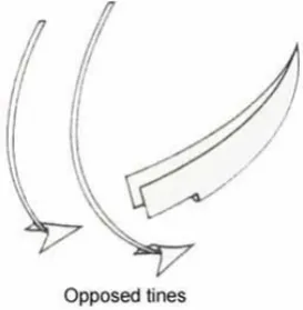
In Figures 65 and 66 each row unit (i.e. opener and press wheel combination) is mounted independently on a spring-loaded trailing arm pivotally attached to the machine’s mainframe toolbar. Another method of balancing the side forces generated by single and compound angle disc coulter openers is to mount them in opposed pairs on a common arm (Figure 67).
The particular design shown in Figure 68 has been developed for twin row planting in frictional soils. Both discs share a common press/depth wheel, the operation of which is shown in Figure 67.
Figure 68: Opposed single disc coulter openers sharing a common press wheel
Single disc coulter type openers have increased in popularity for use in conservation cropping systems over recent years, largely because the single disc coulter’s soil penetration and residue cutting ability enables effective operation over a wide range of soil types and residue conditions without the need for a separate soil and residue cutting device (i.e. an additional vertical disc coulter positioned in front of the opener). Seed placement on vertical or compound single disc coulter openers is accomplished via a dropper tube attached to a wedge shaped placement device similar in position and action to that described for single concave disc type openers. Figure 69 shows a typical seed placement device attached to a single angle disc coulter type opener. In this case, the seed delivery tube is positioned behind the distinctly separate and replaceable, fixed wedge-shaped placement device.
Figure 70 shows a similar view of a single angle disc coulter type opener where the fixed wedge shaped seed placement device has been replaced by a small rotary disc that protects the dropper tube and prevents soil movement back into the furrow before seed placement.
Figure 70: A rotary disc type seed placement device on a single-angle disc coulter opener
Double disc coulter type
Double disc coulter type openers usually consist of two plain, flat disc coulters arranged so that the lower leading edges of the discs touch to cut and displace soil (Figure 71). As the discs roll forward, they cut residue and soil, and displace soil downwards and outwards to form a ‘V’-shaped furrow. The seed delivery tube is fully enclosed by the discs and enables seed to be deposited into the furrow at a position slightly ahead of the point where the trailing edges of the discs leave the soil.
Figure 71: ‘Twin inclined’ and ‘vertical and inclined’ double disc coulter types
Double disc coulter types can be further classified on the basis of disc sizes, angles and alignment. Double disc coulter types can be classified as ‘twin inclined’ or ‘vertical and inclined’ (Figure 71).
The twin inclined disc types are symmetrical; both discs incline uniformly to the vertical as well as to the direction of travel. In the case of the vertical and inclined disc types, one disc is vertical and parallel to the direction of travel, the other inclines in both directions.
Figure 72: Design options within twin inclined types of double disc opener
Figure 73: Design options within one-vertical one-inclined types of double disc opener
incorporating using a notched disc as the leading disc would confer the greatest residue-handling ability on double disc opener types used without soil and residue cutting devices.
Examples of the lower front views of aligned ‘twin inclined’ and ‘one vertical-one inclined’ types of double disc coulter furrow opener are shown in Figure 74.
Figure 74: Aligned ‘twin inclined’ and ‘one vertical-one inclined’ types of double disc opener
Figure 75 shows examples of staggered ‘twin inclined’ and staggered ‘one vertical-one inclined’ double disc coulter type furrow openers.
Figure 75: Staggered ‘twin inclined’ and ‘one vertical-one inclined’ types of double disc opener
Figure 76: A staggered twin inclined double disc coulter with a notched leading coulter
Seed placement on double disc coulter type openers does not require the use of any specialised placement device in addition to the seed delivery tube, as the action of the discs opens and holds the furrow open until seed placement occurs. Nevertheless, dropper tube design plays an important part in the seed placement process.
Where seeds exit from a short dropper tube that terminates some distance from the furrow base (Figure 77), seeds may be distributed over a wider band and not necessarily confined to the base of the furrow. A well-designed dropper tube that extends almost to the base of the furrow provides more uniform placement. Research indicates that if such dropper tubes terminate with a rearward deflection (Figure 78), both seed placement and seed spacing (where appropriate) can be improved.
Triple disc coulter types
Triple disc coulter opener types have a plain, flat vertical disc coulter mounted close to, and in front of, a twin inclined double disc coulter assembly (Figure 79). In design, it approximates that of a twin inclined double disc coulter opener used in conjunction with a disc coulter type dedicated soil and residue cutting device. The leading disc makes a vertical cut in the soil and the double discs form the ‘V’-shaped furrow by displacing the soil downward and outward. The leading disc assists in cutting crop residues and the resulting vertical cut tends to give more control over subsequent soil fracture. Using a flat plain leading disc coulter may result in a more uniform and less disturbed furrow; using a wavy leading disc coulter increases soil disturbance and tends to result in a wider furrow shape.
Figure 79: The layout of a triple disc coulter type furrow opener
[image:10.595.208.390.473.608.2]Figure 80 shows a rear side view of a triple disc coulter opener. The smaller-diameter leading disc is typical of earlier designs and limits residue-handling ability. More recently, the dedicated triple disc coulter type has been largely replaced by a combination of a twin inclined double disc coulter opener and a separate disc coulter soil and residue cutting device. This combination provides greater flexibility in the type, diameter and setting of the leading disc compared to the discrete triple disc coulter unit.
Figure 80: A rear view of a dedicated triple disc coulter type furrow opener
Tine type openers
A wide range of tine type openers is used and an even wider range of names is used for particular shapes/designs within this broad grouping. In general, tine openers have rake angles (i.e. the angle made between the leading edge of the opener and the direction of travel) of less than 90 degrees. Tine type openers tend to ‘dig’ a furrow by penetrating the soil and displacing soil upward and outward to form a ‘U’ or ‘V’-shaped furrow. Under high surface residue conditions tine type openers need to be preceded by a soil and residue cutting device to cut the surface residue.
Tine openers can be broadly classified as ‘dedicated’ or ‘dual purpose’. In general terms, dedicated tine types are relatively narrow and have been specifically designed for use on planting equipment. Dual purpose types are generally wider and include those that have been selected from the range of tine type ground tools traditionally used on both tillage and planting equipment. Figure 81 gives some typical examples of types within both categories. They are discussed below.
Figure 81: The two general types of tine type of furrow opener
Dedicated tine type furrow openers
Figure 83 shows the general form of point type furrow openers. Typically, they have a low rake angle (less than 40 degrees), a narrow leading edge and a pointed tip.
Figure 83: the general form of point type tine openers
The leading edge of point type openers may be flat, rounded or ‘V’-shaped and the body of the point may have small wing extensions to help lift soil to create the furrow or otherwise disturb the soil to improve seed/soil contact. The point has heel clearance to assist with penetration and avoid compacting or smearing the furrow base. Point type openers perform successfully over a wide range of soil types and seedbed conditions but they are ideally suited for use in heavier clay soils and where there is no requirement for seedbed disturbance below the depth of seed placement. A significant advantage in using point type openers is that they are relatively inexpensive, there is a wide range of specific designs available, many are interchangeable with or without the use of adaptors and some individual points can be inverted to allow a change in rake angle, the degree of disturbance, etc.
All three types shown in Figures 84 and 85 are interchangeable via the use of a standard adaptor. Figure 84 shows two examples of point type openers. The wingless version is designed symmetrically, enabling it to be inverted when worn to extend its useful working life. The winged version is simply an adaptation of the same basic shape; one of many variations in the design available to facilitate point selection for particular conditions.
Figure 85 shows a winged point mounted in both positions enabled by reversing (inverting) the point. The change in wing position resulting from inverting the point provides for a degree of flexibility in the nature and the extent of seedbed disturbance resulting from its use. In the ‘wings up’ position the opener creates significantly more disturbance to the seedbed.
Figure 85: An example of a reversible point type opener
Knife points have the general form depicted in Figure 86. They are essentially a blade with a narrow cross-section, normal to the direction of travel, and a relatively large rake angle (60–70 degrees). Knife points create a narrow furrow by displacing soil sideways because of the low critical depth resulting from the narrow cross-section and high rake angle.
Figure 86: The general form of knife type tine openers
Figure 87: A typical knife type tine opener
Inverted ‘T' type tine openers are essentially winged knife type openers; Figure 88 shows their general form. The position of the wings varies depending on the particular design. The wings may be restricted to the lower portion of the blade section or be placed further up the trailing edge.
Figure 88: The general form of inverted ‘T’ type tine openers
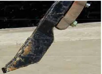
[image:14.595.216.381.74.194.2]Essentially, the wings tend to create disturbance within the seed zone while keeping surface disturbance to a minimum. This action enables the inverted ‘T’ types to successfully operate over a wider range of soil types and conditions than the knife types. Nevertheless, the action of the inverted ‘T’ type makes it unsuited for use in moist clay soils where smearing and soil adhesion to the opener compromises performance. The concept for the bioblade type furrow opener was largely derived from work undertaken to develop and refine the action of the inverted ‘T’ type opener. Figure 89 shows the front and side views of a typical inverted ‘T’ type tine opener.
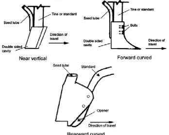
Shoe type tine openers are taken here to include a wide range of tine mounted dedicated furrow openers that can have a near vertical, forward or rearward curved leading edge with side plates that enclose the seed delivery system or otherwise assist in preventing soil movement back into the furrow before seed placement. Figure 90 shows the general forms of this type.
Shoe type openers have been developed essentially for use in conventional, well-prepared seedbeds without significant amounts of surface residue. Given this, the diversity of furrow opening actions resulting from the various forms and their general inapplicability in modern conservation cropping systems they are not further discussed here. Typical examples of all three general forms as described are shown in Figure 91.
[image:15.595.128.477.215.493.2]Figure 90: General form of near vertical and forward and rearward curved shoe type tine openers
Dual-purpose tine type furrow openers
Dual-purpose tine type openers are essentially secondary tillage tools that have been selected to open furrows for seed placement. The three general forms of dual-purpose tine type furrow openers are ‘points’, ‘sweeps’ and ‘duckfoot’ (Figure 92).
Figure 92: The general types of dual-purpose tine type furrow openers
Dual-purpose point type openers differ from dedicated point types in that the leading edge of the dual-purpose point is typically curved rather than straight and is flatter, wider and steeper than the leading edge of the dedicated point. They can be single or reversible and are generally considered inferior in their furrow opening action to dedicated point types. In general, their furrowing opening action is less controlled and gives more seedbed disturbance than their dedicated counterparts, particularly in firm to hard seedbed conditions where soil tends to be shattered rather than cut or parted.
Typical point (reversible), duckfoot and sweep opener types are shown in Figure 93.
Figure 93: Typical point, duckfoot and sweep type, dual purpose tine type furrow openers
A wide diversity of seed placement devices is used with tine type openers. While they vary in complexity, most consist of a dropper tube delivering the seed via a placement device attached to the lower rear portion of the tine, standard or shank that supports the furrow opener. In most cases, the function of the device is to prevent soil movement back into the furrow before seed placement occurs.
In the case of dual purpose tine type openers (i.e. wide points, duckfoot and sweep types) the placement device is usually a very simple ‘U’-shaped piece of metal attached to the rear of the tine through which the seed drops to the furrow. These placement devices (Figure 93) follow in the shadow of the opener and/or tine.
On dedicated tine openers, the placement device used for shoe types is often incorporated into the opener design (Figure 91), where the side plates that prevent soil movement back into the furrow are fully or partly formed by extensions protruding rearwards from the main body of the opener. This is also illustrated in Figure 94 where the rearward curved shoe opener is attached to and fully enclosed by the combined seed delivery and support system.
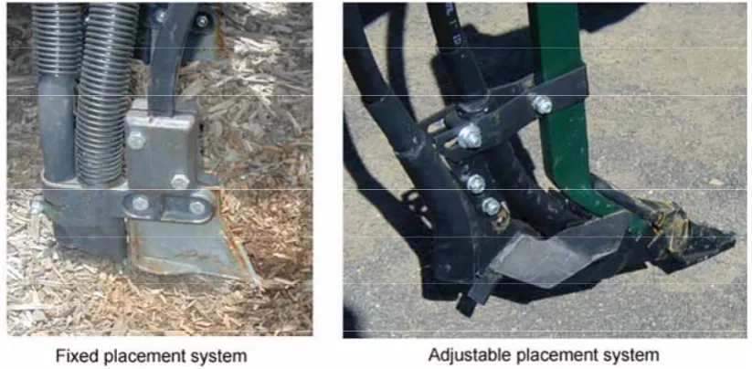
On dedicated tine openers, the placement device for the narrow point, knife and inverted ‘T’ type openers is usually more sophisticated, often with provision for vertical, sideways and rearward adjustment (relative to the opener) to suit particular opener types, soil types and soil conditions. Figure 95 shows a fixed seed and fertiliser placement system attached behind an inverted ‘T’ type opener and an adjustable version of the same type mounted behind a narrow point type opener.
Figure 95: Fixed and adjustable seed and fertiliser placement systems for tine type opener
The bioblade opener
[image:18.595.92.504.177.379.2]The Agrisystems™ cross-slot opener or bioblade furrow opener is one of the more recent developments in opener design. In essence, it combines the attributes of a soil and residue cutting disc coulter with an inverted ‘T’ type tine opener. Conceptually, at least, the bioblade opener was formed by splitting the inverted ‘T’ type opener lengthwise and positioning the front edges of each portion of the split opener so they rubbed on each side of a flat, notched disc coulter. As the opener (Figure 96) is drawn through the soil the disc coulter cuts residue and makes a vertical slot deeper than the intended depth of planting. The vertically adjustable, winged Bio-Blades™ make a horizontal ‘cross-slot’ at the required level below the surface into which the seed and fertiliser fall on opposite sides of the disc.
The low surface disturbance, combined residue/soil cutting and furrow opening capability, and ability to separate seed and fertiliser are key attributes of this opener type. It has shown good capability over a wide range of types and conditions, but requires significant vertical force to ensure penetration in hard soil conditions. Excessive soil cover when planting to depth and the potential to leave loose disturbed soil below the seeding depth, particularly under moist clay soil conditions, may limit performance. This – together with its high cost, complexity and wear rate – has restricted the adoption of this opener type.
Figure 97 shows front, side and rear views of the bioblade type opener. Seed placement is via a dropper feeding seed directly into the space that forms in the shadow of the ‘winged bioblades’ that not only open the furrow but also prevent soil flow back into the furrow before seed placement.
Figure 97: Front, rear and side views of the bioblade type furrow opener
Powered opener types
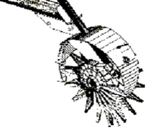
Powered openers were developed in the 1970s in an effort to combine herbicide application and tillage and planting requirements into a single pass operation for pasture renovation. Essentially, these openers employ a powered cutting wheel or disc to cut crop residues and produce a narrow, well-defined, non-compacted furrow of loose soil into which the seed is placed. Figure 98 gives a diagrammatic representation of the powered type opener.
Figure 98: A diagrammatic representation of a powered type furrow opener
Powered openers have demonstrated exceptional ability to operate over a wide range of soil types and conditions, but they have high capital and operating costs compared to most other opener types. This – together with improvements in the performance of other opener designs – has restricted adoption or further development of this opener type. Figure 99 shows a rear side view of a commercially available powered type furrow opener.
Figure 99: The rear side view of a powered type furrow opener
Punch type openers
Punch type openers do not create a furrow in which the seed is placed but rather push or dibble a series of holes into the soil into which one or more seeds are placed. While the concept of using punched or dibbled holes for seed placement has been extensively used in some conventional (particularly horticultural) cropping systems, several units have been developed for use in conservation cropping systems over more recent years.
Most units use a seed meter and an accumulator unit into which the seeds are deposited before being transferred to the ‘punch’ opener for direct deposition into the soil.
While most units use multiple punch openers mounted around a cylinder some have had single vertically reciprocating punch to effect seed placement along the row.
Examples include the single row unit developed in Africa for direct planting through crop residues (Figure 100) and a multi-row unit developed in China to plant through plastic mulch (Figure 101).
[image:20.595.212.366.608.740.2]5.4 Group 4 – Seed firming devices
Seed firming devices are designed to press uncovered seed into the soil at the base of the seed furrow to improve seed/soil contact. While seed firming devices are commonly incorporated in the design of specialised horticultural planting machines using a runner type furrow, their use in other applications has been largely confined to machines using a double disc coulter type furrow opener.
5.4.1 Functional requirements of seed firming devices
Where used, the functional requirements of a seed-firming device are to:
• firm uncovered seed into the moist soil at the base of the furrow to improve the prospects of rapid moisture transfer to the seed; and/or
• assist seed placement in the base of the furrow by reducing the possibility for seed bounce after initial contact with the soil.
5.4.2 Operational requirements of seed firming devices
To achieve their functional requirements the operational requirements of seed firming devices include:
• correctly matching the seed firming device to the width and shape of the furrow to ensure it ‘runs’ on the base of the furrow;
• positioning the seed firming device relative to the furrow opener/seed placement device to ensure it firms the seed on the base of the furrow before any seed covering (i.e. by soil falling back into the furrow) occurs;
• ensuring that (when in use) the device does not interfere with seed spacing requirements by ‘picking up’ or ‘dragging’ seed, particularly when operating under moist clay soil conditions where seed and/or soil may adhere to the device;
• making provision to easily remove or otherwise take the seed firming device out of service when not required or when seedbed conditions are unsuitable for its effective use.
5.4.3 Types of seed firming devices
Most seed firming devices press the seed into the base of the furrow with either a ‘rolling’ or a ‘sliding’ action and can be broadly classified as either ‘seed firming wheels’ or ‘seed firming slides’ (Figure 102).
Figure 102: General types of seed firming devices
Seed firming wheels
Seed firming wheels are comparatively small in both width and diameter and firm the seed by a rolling action. Their use is largely confined to applications where they are fitted close to the rear side plates of a runner type furrow opener to restrict soil flow back over the seed before firming takes place. In most cases, the wheels are mounted on a pivoted trailing arm (Figure 103). This arrangement enables the wheel to be lifted vertically and restrained, rather than having to be removed, when not in use. While suitable for use over a wide range of soil moisture conditions in frictional soil types (sands and loams), the wheel’s tendency to pick up both seed and soil under moist, cohesive soil (clay) conditions often restricts their use.
Seed firming slides
[image:24.595.217.382.159.264.2]Seed firming slides firm the seed by way of a ‘sliding’ rather than ‘rolling’ action and are generally directly fitted to the rear lower portion of the seed dropper tube used in conjunction with a double disc coulter type furrow opener (Figure 104). In this application, the disc coulters enclosing the dropper tube and slide prevent soil movement back over the seed before firming is effected.
5.5 Group 5 – Seed covering devices
Seed covering devices are specifically designed to promote soil flow back into the furrow to cover the seed after placement and/or firming. They play an important role in promoting and stabilising conditions conducive to rapid seed germination and influencing seed emergence and establishment through the manipulation of the depth of soil cover over the seed.
5.5.1 Functional requirements of seed covering devices
The functional requirements of seed covering devices are to:
• assist in the transfer of displaced surface soil back into the furrow for the purpose of covering the seed with soil;
• assist in regulating the depth of soil cover over the seed (i.e. assist in regulating planting depth relative to the final seedbed surface); and
• in some cases, assist in re-levelling the seedbed surface.
Covering the seed with soil helps:
• provide and stabilise an appropriate seed environment (e.g. reduce the rate of moisture loss and provide seed/soil contact to optimise both the rate of moisture transfer and the duration of moisture availability to the seed, reduce temperature fluctuations, etc); and
• protect seed from predators such as birds, mice and insects.
5.5.2 Operational requirements of seed covering devices
To achieve the functional requirements, the operational requirements of seed covering devices include that:
• they can be selected and/or adjusted to enable them to operate effectively over the range of field conditions likely to exist at time of seeding;
• the depth of soil cover is uniform and appropriate for the species sown;
• seeds in the furrow are not displaced during the covering process;
• the soil covering the seed is left in a condition that does not impede shoot emergence; and
• the devices are compatible with the range of anticipated row spacings.
The need for, and the design of, the covering device on a planter depends on many factors, including:
• the soil type and condition;
• the design of the furrow opener;
• the type and amount of surface residue; and
• the speed of operation, etc.
Not all planters have or need dedicated seed covering devices. Some drill seeders, for example, rely solely on soil flow around the opener to cover the seed. In general, the success of this approach requires:
• a well-prepared seedbed – increasing soil ‘tilth’ and ‘friability’ usually improves the potential for soil to flow around the opener and back into the furrow after the seed is placed
adjacent furrow openers and/or cultivating tines may affect the depth/uniformity of soil cover over the seed, particularly if wide openers are used on narrow row spacings. Soil displaced by one opener may be thrown in such a way that it adds to the cover over the adjacent seeded row. In conservation cropping systems where narrow openers are used, a seedbed-firming device may be used to perform both the covering and the firming functions.
5.5.3 Types of seed covering devices
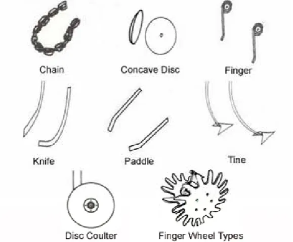
The wide range of dedicated (i.e. row specific, rather than non row specific types) seed covering devices can be generally classified as ‘chain’, ‘concave disc’, ‘finger’, ‘knife’, ‘paddle’, ‘tine’, ‘disc coulter’ or ‘finger wheel’ (Figure 105).
Figure 105: General types of dedicated soil covering devices
Chain type covering devices
[image:26.595.154.444.249.489.2]Chain type covering devices are designed to trail behind the furrow opener and essentially drag loose soil into the furrow to cover the seed. The resulting effect depends on many factors, including the size, length and mass of the chain, and the method of attachment. For example, the chain may be looped, used in combination with a bar or simply trailed (Figure 106).
Chain type covering devices are most easily adapted for use in well-prepared (friable) seedbeds without significant quantities of surface residue and where no significant degree of soil movement is required to fill the furrow. Figure 107 shows the chain and bar configuration attached behind a point type furrow opener and a looped chain configuration attached behind a shoe type furrow opener.
Figure 107: Examples of chain-and-bar and looped chain type covering device
Concave disc type covering devices
As seed-covering devices, concave discs can be mounted singularly or in opposed pairs behind a furrow opener to move soil back into the furrow to cover seed (Figure 108).
Figure 108: Single and double concave disc type covering devices
The double concave disc option is more generally used and is ideally suited when a significant amount of soil is to be moved to adequately cover the seed.
The ability to adjust the discs horizontally and vertically and to change the angle of the disc in relation to the direction of travel provides for flexibility in use and adjustment.
While the cutting action of the concave disc type covering devices allow them to operate effectively under conditions where there’s a significant amount of crop residue on the soil surface, a degree of residue incorporation into the furrow occurs.
Figure 109: Rear view of a double concave disc type covering device
Disc coulter type covering devices
Disc coulters can be mounted singly or in opposed pairs (double disc coulter) behind a furrow opener to move soil back into the furrow to cover seed (Figure 110).
The double disc coulter option is more generally used and is ideally suited to reduced or zero tillage planting situations where their residue cutting and soil displacement function is used to effectively move soil back over the furrow to cover the seed. The disc coulters can be aligned or staggered.
Figure 110: Single and double disc coulter type covering devices
The ability to adjust the disc coulters horizontally and vertically and to change the angle of the coulters in relation to the direction of travel provides flexibility in use and adjustment.
Figure 111: Double disc coulter type covering devices following a seed-firming wheel
Figure 112 shows the rear view of a double disc coulter type covering device. In this case, the disc on the left is being used to cover the seed in a furrow created by a runner type furrow opener (i.e. located immediately behind the seed firming wheel) while the disc on the right is covering fertiliser that has been deposited into a furrow opened by a single concave disc opener.
Figure 112: Double disc coulters, one covering seed the other covering fertiliser
Knife type covering devices
Knife type covering devices need provision for vertical and horizontal adjustment as well as for rotating the knife (relative to the direction of travel) to change the degree of soil movement back into the furrow to cover the seed. They are predominately used in well-prepared seedbeds that do not have any significant surface residue. Figure 114 shows opposed knives positioned behind a seed-firming wheel. The knives are mounted independently on spring-tensioned members.
Figure 114: Opposed knife type covering devices
Paddle type covering devices
Paddle type covering devices can be used singly or in pairs and are essentially elongated blades that are positioned near horizontally on one or both sides of the furrow and have curved trailing ends that effect soil movement back over the furrow to cover the seed as shown in Figure 115.
Figure 115: Paddle type covering devices
[image:30.595.187.411.154.287.2]Paddle type covering devices have similar characteristics to knife types and can be used in similar situations. An opposed pair of paddle type covering devices shown in Figure 116.
Tine type covering devices
[image:31.595.229.366.160.300.2]Tine type covering devices are generally used in opposed pairs and consist of tine standards mounted on either side of the furrow to which a wide variety of point, duckfoot and sweep type ground tools can be attached to effect soil movement back over the furrow to cover the seed. The typical positioning of these devices is shown in Figure 117.
Figure 117: Tine type covering devices
[image:31.595.208.385.415.549.2]Tine type covering devices are commonly used as covering devices on planting machines that have provision to effect full width (entire field surface) cultivation for weed control at time of planting. While the wide range of ground tool types available provide for a degree of flexibility, the major limitations are the high degree of disturbance caused to the seedbed and the limited residue-handling ability resulting from the close proximity of the tines.
Figure 118: Tine type covering devices fitted with reversible point type ground tool
Finger type covering devices
[image:32.595.171.426.146.297.2]Finger type covering devices usually consist of one or more spring steel wire fingers positioned in various spatial arrangements to redistribute loose soil in the immediate row area and thereby cover the seed in the furrow (Figure 119).
Figure 119: Single or multiple finger type covering devices
Finger type covering devices cannot cause significant soil displacement and tend to level rather than move soil. The degree of soil disturbance generally increases with increasing rake angle. However, increasing the finger rake angle to increase disturbance causes a corresponding reduction in residue-handling ability, particularly where multiple fingers are involved. Therefore, finger type devices, particularly multiple finger types, are more commonly used as entire seedbed levelling devices (see Group 7 of the soil-engaging components on page 102) rather than furrow covering devices.
A single finger type covering device is shown in Figure 120. In this application it is used to help cover fertiliser placed in a furrow created by a single disc coulter.
[image:32.595.182.416.463.622.2]Finger wheel type covering devices
[image:33.595.180.418.175.305.2]As a covering device finger wheels can be used singly or as opposed pairs (Figure 121). The range of finger wheel types used is similar, or in most cases identical, to those used as row preparation devices. However, the setting of the wheels is different. Covering finger wheels are set to engage with the soil and angled to move soil back over the row rather than set to have minimum contact with the soil and angled to move residue away from the row as is the case when used as row preparation devices.
Figure 121: Single and double finger wheel covering devices
Examples of single and double finger wheels used as covering devices are shown in Figure 122.
[image:33.595.108.488.362.536.2]5.6 Group 6 – Row specific seedbed firming devices
Row specific seedbed firming devices are designed to firm the soil that covers the seed in a furrow. They differ from entire seedbed firming/levelling devices (i.e. Group 7 of the soil-engaging components, see page 102) in that their area of influence is the immediate row area and does not include the inter-row space. Most of the benefits attributed to row specific seedbed firming devices accrue from optimisation of soil compaction in the seed zone. However, over-compaction of the seedbed can have disastrous effects on seedling development, particularly emergence.
The optimum level of compaction is a compromise between the level that promotes beneficial effects (e.g. improved moisture status around the seed, stabilisation of conditions, etc) and the level that causes adverse effects (e.g. excessive mechanical impedance to shoot development, reduced soil aeration, etc).
The need for, and the type and setting of, a row specific seedbed firming device will be almost application specific and depend on factors such as soil type, soil condition/soil management (soil moisture, soil tilth, surface residues, etc) the type of crop to be planted, and the type and setting of the furrow opener used.
5.6.1 Functional requirements of row specific seedbed firming devices
Under almost all field conditions, firming the soil in the immediate seed zone has been shown to improve both seedling emergence and seedling growth. The significant improvement in emergence (commonly 15–20%) is attributed to a number of factors. These factors give rise to the functional requirements of row specific seedbed firming devices, which include to:
• assist in the general stabilisation of seedbed conditions by firming/compacting the loose soil covering the seed in the furrow;
• improve moisture availability and transfer to the seed by improving seed/soil contact;
• promote rapid and uniform emergence by manipulating both the depth and uniformity of soil cover over the seed;
• improve the prospects for emergence by reducing light penetration into the seedbed and the potential for sub-surface leaf emergence, particularly in the case of heavy clay soils;
• reduce the potential for insect damage to the seed by impeding their movement by firming the soil in the furrow;
• reduce the potential for weed seed germination by not firming soil in the inter-row space; and
• promote benefits that may result from alteration to the micro-relief of the seedbed.
In some cases, e.g. some twin inclined press wheel and finger wheel types, both the seed covering and soil firming functions can be accomplished.
While seedbed firming has been shown to improve emergence and establishment over a wide range of conditions, the effect is most apparent as soil conditions, particularly moisture, become limiting. The use of row specific seedbed firming devices, therefore, enables:
• crops to be established under conditions that would otherwise be called marginal or unsuitable for sowing;
• extension of the planting time available after effective rainfall.
5.6.2 Operational requirements of row specific seedbed firming devices
To achieve the functional requirements, the operational requirements of row specific seedbed firming devices include that:
• ideally, the shape of the device (width, profile, etc) be matched to the furrow shape so its action is not impeded by the firmer soil on either side of the top and walls of the furrow;
• the device be mounted so that it tracks directly over the centre of the furrow at all times;
• the device mounting be such that the pressure exerted on the soil can be easily adjusted and maintained to suit the particular seed type and seedbed conditions;
• the diameter of the device is such that its rolling action is not impeded by soil or residue conditions; and
• the type of device be selected or adjusted to suit the soil condition, e.g. selecting a particular type may reduce soil adhesion when working under moist clay soil conditions.
5.6.3 Types of row specific seedbed firming devices
[image:35.595.132.468.507.669.2]Common row specific seedbed firming devices include press wheels, finger wheels and press coils as generally depicted in Figure 123. Press wheels are the most common type. This results largely from the diversity of types, shapes and sizes that exist. Nevertheless, the use of the finger wheel and press coil types is becoming more common. Each of these general types of row specific seedbed firming devices are discussed below.
Press wheel types
[image:36.595.185.414.134.267.2]The large range of press wheel types precludes a detailed discussion of the attributes of each, however, most can be broadly classified as either ‘over-centre’, ‘zero-pressure’ or ‘inclined’ (Figure 124).
Figure 124: The three general types of press wheel
The relative merits of each type can be inferred from consideration of both their action and their reaction to:
• the type of crop planted; and
• the soil type and condition.
The ability of seedlings to emerge through compacted layers is somewhat species-dependent; the particular form of germination is a major determinant.
Monocotyledonous cereals and grasses (wheat, sorghum) which exhibit hypogeal germination (i.e. the coleoptile emerges) can emerge through compacted layers more easily than dicotyledonous plants exhibiting either epigeal germination (i.e. the hypocotyl emerges as in beans) or hypogeal germination (i.e. the epicotyl emerges as in peas). The major implications of this (in isolation from other factors) are:
• when a crop species known to be more sensitive to compaction is sown, press wheel pressure must be reduced; and
• where appropriate, the use of over-centre type press wheels should be avoided.
Soil type and condition can influence both the press wheel pressure and the press wheel type to be used. Well-prepared seedbeds in a friable condition require less pressure to give the same degree of seed/soil contact than a less well-prepared, cloddy seedbed. Where the level of soil moisture or soil structure is such that firming causes or induces a hard setting layer above the seed, press wheel pressure should be reduced and zero pressure or twin wheel systems used.
In general, over-centre type press wheels are favoured in reduced/no till situations where the seedbed conditions are generally less well-prepared and relatively high pressures over the seeded row are required to obtain good seed/soil contact. The inclined types are ideally suited for use in well-prepared or more friable seedbed conditions. The role of the zero pressure type is somewhere between the other two types. In all cases, press wheel pressure should be selected to suit the crop type and soil conditions.
Over-centre press wheel types
[image:37.595.166.448.133.323.2]Over-centre press wheel types generally have a flat, wedge or ribbed profile and for a given loading tend to exert maximum pressure at the soil surface directly above the seed (Figure 125).
Figure 125: Typical over-centre press wheel profiles
Under reduced or zero tilled conditions, where narrow furrow openers are used, narrow wedge or rounded ribbed types may be required to match the furrow shape and so work effectively. Where wider openers are used, the flat or flat ribbed types may better suit the conditions. Metal, pneumatic and solid rubber types are available. Figure 126 shows examples of the flat, wedge and ribbed types of over-centre press wheel.
[image:37.595.102.497.436.570.2]Zero pressure press wheel types
[image:38.595.162.431.155.354.2]Zero pressure press wheel types usually have a generally concave profile resulting from a hard moulded rubber type, soft centre rubber type (i.e. moulded with hard edges and a soft flexible centre) or split packer metal types. For a given loading, these press wheel types tend to concentrate pressure above but to the sides of the seed zone (Figure 127).
Figure 127: Typical zero pressure press wheel profiles
[image:38.595.129.469.508.734.2]Zero pressure press wheels are particularly useful in friable seedbeds that have a tendency towards hard setting, particularly when more compaction-sensitive crops are grown. Soft centre rubber tyres with a ribbed surface can overcome some of the difficulties associated with hard setting soils. The impressions made by the ribs tend to dry and crack open, allowing emergence through an otherwise almost impenetrable barrier.
Figure 128 shows examples of the moulded, soft centre (plain and ribbed) and the split packer types of zero-pressure type press wheel.
Inclined press wheel types
[image:39.595.107.488.591.729.2]Inclined press wheel types can have a variety of profiles but are generally narrow and inclined to the vertical and/or the direction of travel. Inclined press wheel types may be used individually or as twin inclined pairs (Figure 129) and are often called closing wheels because the angle of inclination assists both covering and closing the furrow.
Figure 129: Inclined press wheel types
For a given loading, these press wheel types tend to concentrate the pressure around the seed but leave the surface soil above the seed relatively uncompacted as suggested in Figure 130.
Figure 130: Indicative pressure zones for inclined press wheels
Inclined press wheel types are suited for use over a wide range of soil types, soil conditions and crop types. Generally, single inclined press wheels are better suited for use with single disc coulter type furrow openers and twin inclined press wheels for use with double disc coulter type furrow openers.
Finger wheel types
[image:40.595.208.389.227.340.2]Finger wheel, row specific seedbed firming devices close and compact soil around the seed with an action similar to that of twin inclined press wheels. While finger wheels used for row preparation or furrow closing may be used for seedbed firming, those specifically designed for firming differ in that their section is concave not flat, and the fingers are shorter and wider (Figure 132).
Figure 132: The typical shape of finger wheels used as a row specific seedbed firming device
[image:40.595.201.396.407.529.2]The finger wheel may be staggered in the direction of travel and the angle of one wheel adjustable (Figure 133) to alter the degree of soil movement and seedbed firming.
Figure 133: Finger wheel adjustment
While the soil is firmed within the immediate seed zone there is little side wall compaction and the surface soil above the seed is left loose and slightly mounded.
A finger wheel may be used in conjunction with an inclined press wheel (Figure 134).
Coil press types
Each coil press, row specific seedbed firming device is manufactured from a single spring steel rod. The rod is rolled to form three coils and attached to an axle at a single central point (Figure 135).
Figure 135: A press coil seedbed firming device
[image:41.595.213.385.362.509.2]When used as a row specific seedbed firming device, individual coil press units are arranged in gangs on a common shaft which is drawn at right angles or slightly offset to the direction of travel. The shaft is supported by two bearings and attached to the planter’s mainframe via an adjustable spring loaded trailing arm (Figure 136).
Figure 136: A gang of coil press seedbed firming devices
When drawn at large angles (30–40˚) to the direction of travel, the coil press unit can be used as a non row specific seedbed levelling device, as shown operating on the left hand side of the planter in Figure 138.
5.7 Group 7 – Non row specific seedbed
firming/levelling devices
Non row specific seedbed firming and/or levelling devices are designed to firm and/or level the entire field surface, i.e. exert their influence over both the row area and the inter-row space. When used, they usually perform the final soil working operation. These devices may be used on a planter in addition to, or as a replacement for, row specific seedbed firming devices.
5.7.1 Functional requirements of non row specific firming/levelling devices
Non row specific seedbed firming and/or levelling devices are generally used to achieve one or more of the following:
• firming the field surface to improve seed germination prospects by increasing seed/soil contact;
• levelling the field surface to facilitate uniformity in the depth of cover over the seed or the effectiveness of subsequent cultural practices, e.g. irrigation, harvesting, etc; and
• controlling small weeds at time of planting.
5.7.2 Operational requirements of non row specific firming/levelling devices
To achieve their functional requirements, the operational requirements for non row specific firming and/or levelling devices include the ability to:
• attach and remove the devices easily;
• adjust the aggressiveness and/or effectiveness of the firming, levelling or weed control functions;
• operate effectively over the range of field/seedbed conditions likely to exist at the time of planting; and
• not impair or otherwise restrict the manoeuvrability of the planting machine.
5.7.3 Types of non row specific seedbed firming/levelling devices
Although a wide range of non row specific seedbed firming and/or levelling devices exist most can be broadly classified as either ‘roller’, ‘packer’ or ‘harrow’ types as generally depicted in Figure 139.
Figure 139: General types of non row specific seedbed firming/levelling devices
Roller type non row specific firming/levelling devices
Rollers firm and level the field surface by applying a vertical downwards force without any significant prior redistribution of surface soil. The uniformity of compaction and/or levelling largely depends on pre-existing soil surface conditions; hollows are removed only to the extent that the ridges can be compacted. As a result, uniform and adequate firming of soil around the seed is unlikely, particularly where the soil surface over the seeded row has been previously depressed by furrow opener and/or press wheel action.
A wide diversity of roller types, shapes and sizes exist and they are manufactured from an equally diverse range of materials including wood, metal and vehicle tyres (Figure 140).
Figure 140: Some types of rollers used as non row specific seedbed firming devices
While the mass of tyre and wooden types is generally fixed, the mass of hollow metal rollers can often be adjusted by adding or removing water.
residue. Rollers are also cheaper than press wheels, so they are often preferred, particularly where seedbeds are well-prepared and level before planting. Figure 141 shows some examples of typical rollers.
Figure 141: Examples of roller types
Packer type non row specific firming/levelling devices
Packer type, non row specific firming and levelling devices have similar characteristics to roller types in that they firm the field surface by applying a vertical downwards force without any significant prior redistribution of surface soil. They differ significantly in that they usually leave the soil surface ‘rilled’ ‘dibbled’ or ‘grooved’, rather than flat, as a result of their usually discontinuous flat, round, tooth or ‘V’-shaped sectional profile. Their more aggressive action also provides for more clod pulverisation in addition to their firming and levelling action.
Spiral packers, cage rollers, toothed packers, disc packers, etc, are some of the range of packer types available. Figure 142 shows examples of flexible toothed and rigid coil type packers.
Harrow type non row specific firming/levelling devices
Compared to roller and packer types that level and firm by rolling, harrows level and firm by a raking action that causes soil displacement and consolidation. This also provides for varying degrees of weed control, depending on the nature and extent of soil disturbance induced.
Peg, finger, leaf, chain and rotary are some of the wide range of harrow types available. While most are designed for use in well-prepared seedbeds with little or no surface residue, the finger and rotary types (Figure 143) are suitable for use where surface residues exist.
Figure 143: Examples of ‘rotary’ and ‘finger’ type harrows
There is considerable diversity within each type of harrow. For example, rotary harrows can be rigid or flexible across their working width (Figure 144) and be designed for shallow or deeper operational working depths.
Figure 144: Examples of rigid and flexible rotary harrows
SECTION 6
Planter furrow opener depth
control components
Effective planting depth is measured as the vertical distance from the seed to the soil surface immediately above the seed. As discussed in Section 2.2, and shown in Figure 145, there is an optimum effective depth of planting for each species and, for given conditions, this depth is typically related to seed size. Generally, small seeds (e.g. most pasture and vegetable crops) need to be planted at very shallow depths (e.g. 3–8 mm) to achieve optimum emergence percentages and the emergence percentage decreases rapidly as the effective depth of sowing increases. Larger seeds (e.g. cereal grain crops) generally need to be planted deeper (e.g. 30 to 60 mm) for optimum emergence percentages and the emergence percentage decreases with shallower or deeper effective depths.
Figure 145: The typical effect of effective planting depth on crop emergence
In addition to influencing the overall emergence and establishment percentages, uniformity in effective planting depth also influences uniformity of emergence, because seeds planted at shallower depths typically emerge faster than seeds planted deeper.
Achieving the optimum effective planting depth essentially depends on two factors:
• the depth to which the furrow is opened relative to the original soil surface; and
• the depth of soil cover over the seed.
6.1 Functional
requirements of furrow opener depth
control mechanisms
As furrow depth is measured relative to the seedbed surface, the functional requirements of furrow opener depth control mechanisms include the ability to:
• open the furrow to the required depth;
• maintain uniformity of depth along the length of the furrow; and
• on multi-row machines, maintain the same depth on all openers across the width of the machine.
6.2 Operational requirements of furrow opener depth
control mechanisms
To meet their functional requirements, the operational requirements of furrow opener depth control mechanisms include the ability to:
• maintain the required accuracy of depth control over the range of soil types and soil surface conditions likely to be encountered at time of planting; and
6.3 Types of furrow opener depth control mechanisms
Depth is measured relative to the soil surface, so for accurate depth control, the opener depth control mechanism should be controlled by a sensor (usually a wheel or wheels) that:
• is in contact with, or otherwise senses opener depth from, the soil surface;
• is located as close as possible to the position where the opener operates; and
• has adequate flotation so as to be able to respond to variations in the soil surface elevation without excessive and/or undue variation in sinkage.
Although these principles generally apply, there is often a trade-off between accuracy of depth control and other considerations, such as overall machine cost or the compatibility of a particular depth control mechanism with other design features of the machine (e.g. opener design, residue-handling ability, row spacing). This, in turn, gives rise to a range of depth control mechanisms with varying levels of performance, particularly as field surface roughness increases.
While a large range of planter depth control mechanisms exist, most can be broadly classified as either ‘frame section gauging’ systems or ‘individual row gauging’ systems, as briefly discussed below.
6.3.1 ‘Frame section gauging systems’ for furrow opener depth control
With frame section gauging systems, the depth of all furrow openers attached to a particular frame or frame section is controlled by the height of the frame relative to the soil surface. To adjust the furrow depth, the machine frame or frame sections are raised or lowered (relative to the soil surface) by adjusting the position (relative to the frame) of the depth and/or transport wheels that support the machine frame in its working position. Figure 146 shows the side and rear view of a trailed, rigid hitch, four-bar, rigid framed cultivator/planter (seed metering and delivery equipment not shown) where:
• the dual purpose (duckfoot) tine type furrow openers are attached directly to, and are evenly spaced over, the four transverse tool bars;
• the depth/transport wheels are centrally located (relative to the bars) outside the frame; and
[image:49.595.91.511.443.645.2]• the machine is working on a flat (level) seedbed surface.
It can be seen that:
• the position of the frame relative to the soil surface controls furrow opener depth;
• the attitude of the frame is controlled by both the depth/transport wheels and the tractor drawbar; and
• when the frame is parallel to a flat seedbed surface, depth control, both along the rows and between furrow openers across the width of the machine, is accurate.
Figure 147 shows the same machine operating on an irregular seedbed surface and clearly shows the limitations of the ‘frame section gauging’ system of furrow opener depth control. Nevertheless, it also serves to illustrate the general principles earlier outlined, i.e. the depth of the openers closer to the depth/transport wheels (i.e. those towards the outer edge of two central bars – bars 2 and 3) are more accurately controlled.
Figure 147: A trailed, rigid hitch, 4-bar rigid frame planter operating on an irregular surface
There are a number of ways to improve the accuracy of depth control on machines that use ‘frame section gauging’ systems. All involve additional cost and most involve reducing the effective width and/or length of the frame section. In essence, both approaches aim to bring the openers closer to a depth/transport wheel as shown in Figure 148.
Figure 148 shows the side and rear views of a trailed, flexible hitch, 4- bar, 3- section, flexible framed cultivator/planter working on an irregular seedbed surface. It shows the improvement gained by using a flexible hitch and a flexible frame to reduce length and width of the frame sections respectively. The flexible hitch shortens the effective length of the frame and thus improves depth control along the length of the furrow. The flexible frame divides the total width of the frame into a number of smaller individual frame sections, improving the uniformity of depth control across the width of the machine.
The frame section gauging method of depth control is often used on planters such as those commonly called ‘airseeders’ and ‘grain drills’, typical examples of which are shown in Figures 149 and 150 respectively.
Figure 149 shows a rear side view of a trailed rigid hitch, 4-bar, 3-section, flexible framed cultivator based airseeder type of drill planter. The individual furrow openers are attached via tine or standard to one of the three frame sections. The method of depth control is clearly ‘machine section gauging’, as the position of a frame section relative to the soil surface controls the depth of all openers attached to the frame section.
Figure 149: A drill planter utilising frame section gauging for furrow opener depth control
Figure 150 shows the rear side view of an Australian drill planter commonly known as a combine. This machine differs from some other drill planters in that it has a combination of tillage and planting ground tools attached to a rigid, 6-bar sub frame. The combination of tillage and planting ground tools provide full width cultivation for weed control at time of planting. Nevertheless, the method of furrow opener depth control is frame section gauging, as the depth of all the furrow openers is dependent on the position of the machine’s frame relative to the soil surface.
6.3.2 ‘Individual row gauging systems’ for furrow opener depth control
With individual row gauging systems each opener has its own depth control mechanism, i.e. each opener is able to move independently of all others on the machine. Their movement (within a working range) is not constrained by the toolbar or mainframe to which they are attached.
There is a large range of individual row gauging depth control systems, but most can be broadly classified as either ‘parallelogram’ or ‘trailing arm’ systems. Variations within each type can be broadly sub-classified on the basis of the number and the location of the gauge wheels used.
Parallelogram systems of individual row depth control
In parallelogram systems, each furrow opener is attached to an individual frame section or unit that is attached to the machine’s mainframe or toolbar by a parallelogram linkage. The parallelogram linkage allows the individual opener’s frame section freedom of vertical movement, thus isolating it from variations in tool bar or mainframe height as well providing for independent movement relative to other such opener frames attached to the same toolbar or mainframe.
The height of the individual frame section relative to the seedbed surface, and hence the furrow opener depth, is controlled by a gauge/press wheel attached to the frame (Figure 151). Opener depth is changed by moving either the gauge wheel(s) or the opener up or down relative to the frame.
Figure 151: The parallelogram method of individual opener depth control
Figure 152: Gauge wheel positions for depth control on parallelogram systems
Figure 153: ‘Twin’ gauge wheel positions for parallelogram systems
Unlike the ‘twin’ wheel system in Figure 153, where the opener frame is pivotally attached to the parallelogram and its attitude depends on the relative vertical positions of the front and rear gauge wheels, the frame in Figure 152 is an extension of the parallelogram’s rear vertical member. The parallelogram ensures the frame maintains the same attitude (essentially horizontal to the seedbed surface) throughout its range (arc) of vertical movement. This arrangement helps facilitate the positioning of, for example, seed boxes and seed metering systems on the frame and is typically used on unit type precision planters.
Dedicated gauge wheels (i.e. those mounted adjacent to the opener) give better depth control than either front or rear mounted gauge wheels (i.e. relative to the opener), essentially because of their closer proximity to the opener. Because of the averaging effect, the performance of the twin wheel configuration is generally considered to be somewhere between that of the dedicated and the front and/or rear wheel systems.
Rear gauge wheel type
Figure 154 shows the side view of a toolbar mounted unit type precision planter where the seed box, seed metering system (vacuum disc type) and runner type opener and rear gauge/press wheel are attached to a frame that is suspended from the toolbar by way of a parallelogram linkage. The depth of the furrow opener is independent of the tool bar (by virtue of the parallelogram) and controlled by the position of the rear gauge/press wheel’s position relative to the frame.
Figure 154: A unit planter utilising a ‘rear gauge wheel’ type of the parallelogram system
Dedicated gauge wheel type
Figure 155 shows a side view of a unit type precision planter where the seed box, seed metering system (vacuum disc), double disc opener and twin inclined press wheels are attached to a frame suspended from the toolbar by a parallelogram linkage. The depth of the furrow opener is independent of both the toolbar (by virtue of the parallelogram) and the press wheels (by virtue of the pivot point by which the press wheels are attached to the frame section) and is controlled by the dedicated gauge wheels positioned on either side of the double disc type opener.
Front gauge wheel type
Figure 156 shows the side view of a furrow opener frame mounted to a toolbar by way of a parallelogram. The frame position relative to the soil surface is controlled by the depth/gauge wheel mounted forward of the opener. Opener depth is therefore controlled by the front mounted gauge wheel and adjusted by moving the opener up or down relative to the frame.
Figure 156: A furrow opener utilising a ‘front gauge wheel’ type of the parallelogram system
[image:55.595.133.465.433.635.2]Twin gauge wheel type
Figure 157 shows the side view of a runner opener attached to a frame which is connected to the machine’s toolbar by way of a parallelogram linkage. Opener depth is controlled by the front and rear wheels supporting the frame to which the opener is attached.
Trailing arm systems of individual row depth control
In trailing arm systems the furrow opener is connected either directly or indirectly to the machine’s mainframe or toolbar by way of a pivotally attached trailing arm. This pivot point allows the opener freedom of vertical (and in some cases horizontal) movement in relation to the machine’s mainframe or toolbar and to other openers across the width of the machine.
The position of the arm, and hence the opener’s depth, is controlled independently by a wheel attached directly to the arm or by wheels supporting a frame attached to the arm. The position of the depth or gauge wheel(s) is important in relation to accuracy of furrow opener depth control and these positions can be broadly classified as being ‘beside’ or ‘behind’ the furrow opener (Figure 158) or as a ‘forward and behind’ system (Figure 159). Depth or gauge wheels mounted ‘beside’, ‘behind’ or ‘forward and behind’ the opener are generally defined as ‘dedicated’, ‘rear’ and ‘twin’ wheel systems respectively.
Figure 158: ‘Dedicated’ and ‘rear’ gauge wheel positions for trailing arm type depth control systems
Figure 159: ‘Twin’ gauge wheel positions for trailing arm type depth control systems
Dedicated gauge wheels (i.e. those mounted adjacent to the opener) provide better depth control than the rear mounted gauge wheel (i.e. relative to the opener), essentially because of their closer proximity to the opener. Because of the averaging effect, the performance of the twin wheel configuration is generally considered to be somewhere between that of the dedicated and the rear wheel systems.
Nevertheless, both the ‘rear’ and ‘twin’ gauge wheel systems are commonly used because, in addition to providing for depth control, the wheels may be used for other purposes. For example, rear mounted gauge wheels can also be used as a row specific firming device i.e. used as a press wheel. The front gauge wheel in the twin wheel type could also be used as a roller type row preparation device.
Rear gauge wheel type
Figure 160 shows the side view of a combined seed and fertiliser placement system. The fertiliser is placed below the seed via a dropper tube behind the leading tine type opener. The seed is placed via the rearward curved shoe type furrow opener attached to the trailing arm pivotally mounted to the fertiliser tine and supported by a rear mounted gauge/press wheel.
The depth of the shoe type opener is adjusted by raising or lowering it relative to the trailing arm, the position of which, relative to the soil surface, is controlled by the rear press/gauge wheel.
Figure 160: A furrow opener utilising a rear gauge wheel type of the trailing arm system of depth control
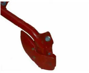
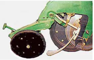
Dedicated gauge wheel type
Figure 161 shows a single compound angle disc coulter opener mounted on a trailing arm. A dedicated gauge wheel mounted beside the disc controls the depth of the opener.
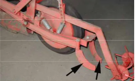
Twin gauge wheel type
Figure 162 shows the side view of a narrow point type furrow opener mounted on a frame that is attached to the planter mainframe by way of a trailing arm. The twin wheels, i.e. the one positioned in front of and the one positioned behind the opener, control the position of the frame relative to the soil surface and hence opener depth.