Multiuser Decorrelating Based Long-Range Frequency-Domain Channel Transfer Function
Prediction in Multicarrier DS-CDMA Systems
Bin Hu, Wei Liu, Lie-Liang Yang and Lajos Hanzo School of ECS, University of Southampton, SO17 1BJ, UK.
Tel: +44-23-8059 3125, Fax: +44-23-8059 4508
Email: bh202r,wl03r,lly,[email protected]; http://www-mobile.ecs.soton.ac.uk
Abstract— In this contribution, multiuser decorrelating based frequency-domain channel estimation and long range channel prediction techniques are proposed for a generalized Multicarrier DS-CDMA (MC DS-CDMA) system communicating over a fast fading and frequency-selective channel. In the MC DS-CDMA system considered, the channel transfer function (CTF) is estimated in the frequency-domain with the aid of pilot symbols by invoking the multiuser decorrelating based channel estimation technique, in order to reduce the effects of both the Multiuser Interference (MUI) and the background noise. Then, Kalman filter as-sisted long-range channel prediction is carried out with the aid of both the current and previous frequency-domain CTFs for the sake of predicting the future CTFs. Furthermore, a sinc-interpolator is employed for the sake of deriving the frequency-domain CTFs associated with the data symbols. Our simulation results show that for a reasonable signal-to-noise ratio (SNR) value the proposed frequency-domain multiuser decorrelating based channel estimator is robust to the effects of both the MUI as well as the noise.
I. INTRODUCTION
One of the most challenging problems in high data rate wireless sys-tems is that of overcoming the effects of dispersion imposed by mul-tipath propagation. Based on a combination of Direct Sequence Code Division Multiple Access (DS-CDMA) and Orthogonal Frequency Di-vision Multiplexing (OFDM), MC DS-CDMA [1], [2], [3], [4], [5], has been proposed for a variety of high-rate wireless communication applications. In this contribution, we discuss the generalized MC DS-CDMA system investigated in [6], which incorporates the subclasses of both multitone DS-CDMA [3] and orthogonal MC DS-CDMA [4] as special cases. In the MC DS-CDMA system considered, the en-tire frequency band is divided into a number of subcarriers. Signals transmitted in each subcarrier experience flat fading, provided that the bandwidth of each subcarrier is lower than the coherence bandwidth of the channel. Moreover, a sufficient long cyclic prefix can be incorpo-rated for the sake of compensating for both the asynchronous delay dif-ferences of the different users as well as for the delay-spread-induced inter-symbol interference (ISI) imposed by the dispersive channel [2]. In this case, each of the subcarriers can be estimated or predicted using a variety of schemes designed for flat fading channels.
On the other hand, in future wireless systems, the carrier frequency is likely to be high, which results in normalized high Doppler frequen-cies. Thus, using the outdated channel transfer function (CTF) esti-mated based on the past received data using Decision Directed Chan-nel Estimation (DDCE) principles [2] may not be sufficiently accurate. However, with the aid of long range CTF prediction, the future Chan-nel Impulse Response (CIR) or CTF may be estimated sufficiently ac-curately [7]. Various algorithms have been proposed in the literature [7], [8], [9], [10], [11] for the sake of implementing long range CIR or
The financial support of the European Union under the auspices of the Phoenix and Newcom projects and that of the EPSRC,UK is gratefully ac-knowledged.
CTF prediction. In [7], the CIR was predicted based on the Minimum Mean Square Error (MMSE) estimation principles. The most impor-tant characteristic of this algorithm is that the sampling rate is typically significantly lower than the data rate. In [8] the ROOT-MUSIC algo-rithm was invoked for non-dispersive channel envelope prediction. By contrast, the ESPRIT algorithm was employed for the prediction of fast-fading wideband channels in [9]. Furthermore, in [10], [11] both the one-dimensional 1-D and 2-D Unitary-ESPRIT algorithms have been employed for estimating the CTF. Once the CTF has been de-termined, its future values can be extrapolated in both the time and frequency domain using the techniques proposed in Chapters 15 and 16 of [2].
By contrast, the novelty of this paper is that we invoke the multiuser decorrelating based channel estimation scheme in the context of gener-alized MC DS-CDMA for the sake of estimating the frequency-domain (FD) CTF while reducing the effects of both the Multiuser Interference (MUI) and the background noise. Then, Kalman filter assisted long range FDCTF prediction is carried out in order to predict the future CTFs based on both the current and previous CTFs determined with the aid of the dedicated MC DS-CDMA pilot symbols to be described in Section III. Finally, we generate the frequency-domain CTFs asso-ciated with the data symbols by employing a sinc interpolator.
The rest of this paper is organized as follows. In Section II the philosophy of the uplink generalized Multicarrier DS-CDMA system and the wideband wireless channel are briefly described. In Section III the multiuser decorrelating based channel estimation scheme is in-vestigated, while the long range channel predictor assisted by both a Kalman filter and a sinc-interpolator are considered in Section IV. The attainable performance is studied in Section V. Finally, Section VI of-fers our conclusions.
II. SYSTEMMODELS
IFFT P/S LPF
cos(2πfct) bk(t)
ck(t)
c k,1
c k,2
c k,V
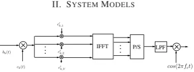
Fig. 1. Transmitter schematic of MC DS-CDMA using both time-domain and frequency-domain spreading
The transmitter of the generalized MC DS-CDMA system is por-trayed in Fig.1. At the transmitter side, the binary data streambk(t)is spread using anN-chip time domain DS spreading waveformck(t). The DS spread signals are simultaneously modulated using Binary Phase Shift Keying (BPSK) and then spread using a frequency do-main orthogonal spreading sequenceck= [ck,1, ck,2, . . . , ck,V]of lengthV, where we haveck·cHk = 1. In our investigations we
[image:1.595.346.537.540.611.2]assume that OFDM usingV subcarriers was invoked [2], whereV consecutive chips of the MC DS-CDMA spreading sequences were mapped toV different subcarriers during an OFDM symbol and hence the OFDM symbol duration wasTc = Tb/N. The spread OFDM chip-vector ofV subcarriers can be expressed assk =ckbkck(t) = [s1, s2, ..., sV]. The Inverse Fast Fourier Transform (IFFT) is then in-voked for modulating theV subcarriers by using the spread OFDM chip-vectorsk[2]. The output signal of the IFFT-based demodulator is a block ofV number of time domain samples in parallel form. After parallel to serial (P/S) conversion these time domain signals are trans-mitted through a multipath fading channel, which is assumed to have Lpaths.
In our investigations, block-based data transmission is consid-ered where there are M useful MC DS-CDMA symbols, namely
[bk,0j, bk,1j,· · ·, bk,(M−1)j], in jth block. Thus the kth user’s jth transmitted signal block after IFFT and P/S conversion can be ex-pressed as[˜sk,0j,˜sk,1j,· · ·,˜sk,(M−1)j], where the chip-vector˜sk,mj
represents the IFFT of the spread OFDM chip-vectorsk,mj, which can be expressed as
sk,mj=ckbk,mjck(t). (1)
A cyclic prefix of lengthLis inserted in the chip-vector˜sk,mjprior to transmission for the sake of compensating for both the asynchronous delay differences of the different users as well as for the delay-spread-induced ISI imposed by the dispersive channel [2]. Furthermore, a guard interval of lengthτmaxis inserted in each transmission block for the sake of preventing the inter-symbol-block-interference among different users, whereτmaxis the maximum delay of all users, which is normalized to the OFDM symbol periodTc=Tb/N. Consequently, a transmission block is comprised of{(V+L−1)N M+τmaxV}chips and hence the duration of a transmission blockTB may be expressed asTB={(V+L−1)N M+τmaxV} ·Tc, whereTc =N VTb is the chip-duration.
We assume that the CIR encountered is time-invariant during a transmission block [12]. Therefore, the CIR corresponding to thejth transmission block can be expressed as:
hkj(t) =
L−1
X
=0
hkj,·δ(t−τk,Tc), (2)
wherehkj,is the complex channel gain experienced by the signal of thekth user in theth path, which obeys Rayleigh fading, whileτk, is the kth user’s delay in the th path. Let us assume that the first user corresponding tok= 1is the user-of-interest and his/her delay is τk,0= 0for simplicity.
At the receiver, the TD samples of the received signal correspond-ing to the cyclic prefix are first removed and V-point FFT is in-voked for demodulating the remaining V samples and generating the demodulated subcarrier signals in the FD [2]. Consequently, the received signal can be expressed in vectorial form as rmj = [rmj,0, rmj,2, . . . , rmj,V−1]T,
rmj =
K
X
k=1
CkHkjbk,mjck(t) +nmj=Gjbmj+nmj, (3)
where Hkj = [Hkj,0, Hkj,2, . . . , Hkj,V−1]T denotes the FDCTF, and Ck = diag{ck}. The matrixGj in Eq.(3) is an(V ×K) -dimensional matrix comprising both the channel’s complex-valued FD fading factors and the FD spreading signatures of all the K users,
hence we haveGj = [g1j,g2j, . . . ,gKj], where gkj = CkHkj. Furthermore, the vectorbmj = [b1,mjc1(t), b2,mjc2(t),
. . . , bK,mjcK(t)]T is the data vector andn
mj is the Additive white Gaussian Noise (AWGN) vector associated with the covariance matrix ofσ2IV, whereIV denotes the(V ×V)-dimensional identity matrix. Finally, the(V ×M N)-dimensional matrixRjcorresponding to the jth received signal block may be expressed as
Rj=GjBj+Nj, (4)
where we haveBj= [b0j,b1j,· · ·,b(M−1)j]andNjis contributed bynmjof Eq.(3).
Since we assume that a cyclic prefix of lengthLwas inserted, no OFDM ISI is incurred. Hence the FDCTFHkjin Eq.(3) can be ex-pressed as theV-point DFT of the CIRhkj= [hkj,0, . . . , hkj,L−1]T. More explicitly, we haveHkj=FL·hkj, whereFLis an(V ×L) -dimensional matrix, which is given by the firstLcolumns of the DFT matrixFformulated as:
F=
0 B B B @
1 1 . . . 1
1 e−j2π/V . . . e−j2π(V−1)/V ..
. ... . .. ...
1 e−j2π(V−1)/V . . . e−j2π(V−1)(V−1)/V
1 C C C
A. (5)
III. CHANNELESTIMATION
Pilot-aided channel estimation in OFDM/MC DS-CDMA systems may be carried out either by including appropriately spaced pilot subcarriers in all symbols as in [2], or by transmitting dedicated OFDM/MC DS-CDMA symbols containing no data-bearing subcar-riers, followed by a number of dedicated data symbols having no pilot subcarriers [13]. In this contribution the latter technique is used. In order to mitigate the effects of both the MUI and the background noise imposed on the FDCTF prediction, channel estimation is typically car-ried out prior to channel prediction [7]. In [14] multiuser decorrelating technique was first proposed for signal detection in multiple user sce-nario. By contrast, we invoked multiuser decorrelating technique [14] in our FDCTF estimation scheme for the sake of suppressing the ef-fects of MUI. When the pilot symbol block is received, we multiply both sides of Eq.(4) with the matrixBH
j(BjBHj)−1 generated from the pilot symbols, and attain an estimate of the matrixGj encapsulat-ing both the FDCTFHkjand the FD spreading signaturesCkof all theKusers as follows:
˜
Gj=Gj+NjBHj (BjBHj)−1=Gj+ ˜Nj, (6)
wherejdenotes the index of the received symbol blocks andN˜j is a(V ×K)-dimensional noise matrix. Consequently, the first column of the matrixG˜j, which corresponds to the desired user, is given by
˜
g1j = g1j+ ˆn1j, where the (V ×1)-dimensional noise vector is the first column of the noise matrixN˜j. Upon multiplying the vector
˜
g1jwith the matrixCH1, we obtain the estimate of the desired user’s FDCTFH1j, which can be expressed as
˜
H1j=H1j+CH1 nˆ1j=H1j+ ˜n1j, (7)
According to [15], the autocorrelation function ofHj,vcan be ex-pressed as
r[Δj; Δv] =E[Hj,vHj∗,v] =rt[Δj]rf[Δv], (8)
whereΔj = j−j, Δv = v−v, andrt[Δj]is the time-domain symbol-spaced autocorrelation function, which can be expressed as [15]
rt[Δj] =J0(2πfdmΔjTB), (9)
withJ0(·)representing the zero-order Bessel function of the first kind andfdmdenoting the maximum Doppler frequency. By contrast, the frequency-domain symbol-spaced autocorrelation functionrf[Δv]in Eq.(8) is given by [16]
rf[Δv] =
LX−1
=0
σ2e−j2πΔvf0τ, (10)
where we havef0= 1/(M Tb), whileτdenotes the delay of theth multipath component andσ2 is its average power. In contrast to the autocorrelation function ofHj,vin Eq.(8), the autocorrelation function of its estimateH˜j,vin Eq.(7) is given by
E[ ˜H(j,v)H˜(∗j,v)] =rt[Δj]rf[Δv] +V σ2δ(Δj)δ(Δv). (11)
Furthermore, the cross-correlation betweenH˜j,vandHj,vcan be ex-pressed as
E[ ˜Hj,vHj∗,v] =rt[Δj]rf[Δv]. (12)
Based on Eq.(7) the estimated FDCTF can be formulated as
ˆ
Hj=DHj H˜j, (13)
whereHˆjdenotes the estimate ofHjand the(V ×V)-dimensional matrixDj = [dj,0,dj,1,· · ·,dj,V−1]represents the FD coefficient matrix of the estimation filter designed for estimating Hj, where
dj,v = [dj,v0, dj,v1,· · ·, dj,v(V−1)]Tis a(V ×1)-dimensional vec-tor. The MMSE based coefficient matrixDjmay be obtained by using classic Wiener filtering, which is formulated as [17]
Dj=R−˜1
HH˜RHH˜ , (14)
whereRH˜H˜ =E[ ˜HjH˜Hj]is the(V×V)-dimensional autocorrelation matrix ofH˜j, whileRHH˜ =E[ ˜HjHHj]is the(V ×V)-dimensional cross-correlation matrix.
The minimum MSE (MMSE)Jf o(j,v)of the FDCTF estimator after FD filtering can be expressed as [17]
Jf o(j,v)=rf[0]−rHf,vR−˜1
HH˜rf,v, (15)
whererf,v = E[ ˜HjHj,v∗ ]is thevth column of the cross-correlation matrixRHH˜ .
After FDCTF estimation filtering of the past FDCTFS in the MMSE sense,Hˆj,vcan be expressed as
ˆ
Hj,v=Hj,v+ζj,v, (16)
whereζj,vis a zero-mean process having a variance ofJf o(j,v), which represents the estimation error betweenHˆj,vandHj,v. Based on the property thatζj,vis independent of bothHˆj,vandζj,v, provided that we havej =j[15], the autocorrelation function ofHˆj,vat a given frequency may be expressed as:
E[ ˆHj,vHˆj∗,v] =rt[Δj]rf[0] +Jf o(j,v)δ(Δj). (17)
FFT FFT
J
FDCTF estimation
FDCTF prediction by Kalman filter Estimated FDCTF
Predicted FDCTF FDCTF
estimation
Estimated FDCTF
pilot data
data data pilotdata datapilotdata
J
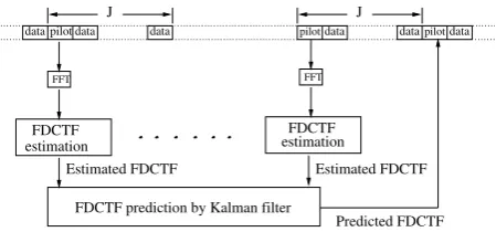
Fig. 2. Illustration of long range prediction for narrowband systems.
IV. CHANNELPREDICTION ANDINTERPOLATION In this contribution we assume that a dedicated pilot OFDM/MC DS-CDMA symbol block having the same number of symbols as the data symbol block is inserted before everyJ−1transmission blocks and theJconsecutive transmission blocks are treated as a pilot-aided transmission frame in this investigation. As portrayed in Fig.2, the FDCTF associated with the next OFDM/MC DS-CDMA pilot symbol block is predicted with the aid of all the pilot blocks available from the past by invoking long-range prediction. As described in Section I, the FDCTFHj,vexperiences narrowband fading at a given subcarrier, provided that the bandwidth of each subcarrier is lower than the coher-ence bandwidth of the channel. Thus, a set ofV Kalman filters can be used for predicting the future FDCTFs at each of theV subcarriers.
For a given FD subcarrierv, v = 1,2, . . . , V, the FDCTF can be described by an AR model [18], which is given by
Hj,v=
P
X
p=1
apHj−p,v+wj,v, (18)
where{ap}represents the AR coefficients derived in [18] andwj,vis the AWGN.
According to [17], the Kalman filtering process used for predicting the FDCTF from all the past values on a subcarrier basis is formulated as
˘
Hj,v=Fj−1,vH˘j−1,v+wj,v, (19)
where we haveH˘j,v= [Hj,v, Hj−1,v,· · ·, Hj−P+1,v]T andwj,v= [w(j,v),0,· · ·,0]T is the(P ×1)-dimensional process noise vector. In Eq.(19),Fj−1,vis the(P×P)-dimensional transition matrix from timej−1toj[17], which is given by
Fj−1,v=
2 6 6 6 4
a1 · · · aP−1 aP
1 · · · 0 0
..
. . .. ... ...
0 · · · 1 0
3 7 7 7
5. (20)
Furthermore, according to Eq.(16) the Kalman measurement equation [17] can be formulated as
ˆ
Hj,v=Cj,vH˘j,v+ζj,v, (21)
whereCj,v = [1,0,· · ·,0]is a(1×P)-dimensional measurement matrix. Consequently, the Kalman filter based FDCTF prediction can be formulated as [17]
`
H[(j+1,v)|(j,v)]=Fj,vH`[(j,v)|(j−1,v)]+G(j,v)αj,v, (22)
where H`[(j+1,v)|(j,v)] represents the MMSE prediction of H˘j+1,v
[image:3.595.325.550.67.172.2]0 20 40 60 80 100 120 140 160 180 200
Ŧ15
Ŧ10
Ŧ5 0 5
Time expressed in pilot symbol blocks
Envelope in dB
[image:4.595.329.548.76.211.2]True CTF Predicted CTF 15 users Predicted CTF 1 user
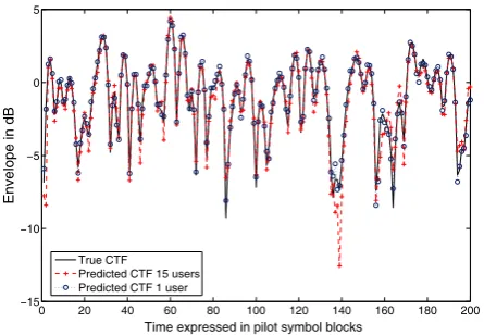
Fig. 3. The true CTF magnitude and the Kalman filter based predicted CTF magnitude of the 16th subcarrier, when assuming that the spacing of pilot sym-bol blocks wasJ= 30transmission blocks, the maximum Doppler frequency
wasfdm= 100Hz, the transmission block duration wasTB = 0.00004s,
the number of multipath components wasL= 5, the length of the transmis-sion block wasM = 10, the length of the cyclic prefix wasL−1 = 4, the power intensity wasσ2 = 0.2for each multipath component and we had
Eb/N0= 25dB. Furthermore, the order of the Kalman filter wasP = 20.
innovation process, respectively [17]. According to [18], we have
Fj,v=Fj−1,vin our investigations.
After long range FDCTF prediction, we attain the specific CTF cor-responding to the data symbol block to be demodulated by interpolat-ing the CTF overK number of consecutive pilot symbol blocks. In [19], a sinc interpolator was proposed for conventional single-carrier modulation, where the fading amplitude of thejth data symbol in the nth transmitted frame was estimated from theKnumber of surround-ing pilot symbols, includsurround-ing the pilot symbols of the(K −1)/2 previ-ous frames, the current frame and of the(K−1)/2subsequent frames, which were predicted in advance by using Kalman filtering assisted FDCTF prediction. In this spirit, the estimate of the FDCTFHˆj
n cor-responding to thejth MC DS-CDMA data symbol block in thenth MC DS-CDMA frame seen in Fig.2 may be expressed as [19]
ˆ Hnj=
KX/2
k=−(K−1)/2
fkjHˆn+k, (23)
wherej= 1, . . . , J−1is the MC DS-CDMA data symbol block index between two pilot symbol blocks portrayed in Fig.2 whilefj
kdenotes the real-valued interpolation coefficient, which is computed from the sinc function as
fkj=sinc(j
J−k). (24)
V. SIMULATIONRESULTS
In this section we quantify the achievable performance of the gen-eralized MC DS-CDMA system communicating over aL = 5paths dispersive Rayleigh fading channel contaminated by AWGN employ-ing 15-chip Gold codes as TD spreademploy-ing sequences and 32-chip Walsh codes as the FD spreading codes.
In Fig.3 the FD envelope of the true CTFHj,vand its Kalman fil-ter based FDCTF predictionH`[(j,v)|(j−1,n)] are shown, when stip-ulating the assumption that the maximum Doppler frequency was
0 20 40 60 80 100 120 140 160 180 200
10Ŧ3 10Ŧ2 10Ŧ1 100
Time expressed in pilot symbol blocks
MMSE
[image:4.595.64.287.79.233.2]20dB J=20 30dB J=20 20dB J=30 30dB J=30
Fig. 4. The CTF MMSE versus the time expressed in terms of the num-ber of the pilot symbol blocks for the Kalman filter based long-range FD-CTF prediction of the16th subcarrier, when assuming that the maximum Doppler frequency wasfdm= 100Hz, the transmission block duration was
TB = 0.00004s, the number of multipath components wasL = 5, the
length of transmission block wasM= 10, the length of the cyclic prefix was
L−1 = 4, the power intensity wasσ2l = 0.2for each multipath component
and the order of the Kalman filter wasP= 20. In this simulation, we had both
Eb/N0 = 20dBandEb/N0 = 30dB. Furthermore, the spacingJof the
pilot symbol block was assigned one of two different values: namely 20 and 30.
fdm = 100Hz, the number of multipath components wasL = 5, the length of the pilot block wasM= 10, the cyclic prefix was consti-tuted byL−1 = 4chips, the power intensity wasσ2= 0.2for each of theL= 5multipath components, while the order of the Kalman filter wasP = 20. Furthermore, we hadEb/N0= 25dBand the transmis-sion block duration wasTB = 0.00004s, while the spacing of pilot symbol blocks wasJ= 30. We can observe from Fig.3 that when the SNR is sufficiently high, the Kalman filter based FDCTF predictor is capable of closely tracking the wideband channel’s FDCTF. Further-more, by employing multiuser decorrelating based channel estimation, the system supportingK = 15users achieved a near-single-user per-formance, since the MUI has been suppressed.
In Fig.4 we evaluated the achievable FDCTF MMSE performance versus the time expressed in terms of the number of the pilot symbol blocks used by for the Kalman filter based FDCTF predictor. In these investigations, we hadEb/N0 = 20dBandEb/N0 = 30dB. All other parameters were the same as those in Fig.3. In Fig.4 the FDCTF MMSE associated with bothJ= 20andJ= 30was recorded. Fig.4 demonstrates that the MMSE reaches a certain residual value, as the number of pilot symbol blocks used for Kalman filtering based predic-tion is increased. Moreover, for a fixed value ofEb/N0, as expected the MMSE corresponding toJ = 5is lower than that corresponding toJ= 30.
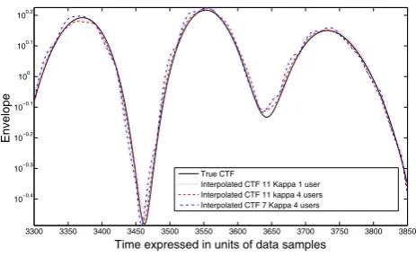
In Fig.5 we evaluated the attainable FDCTF interpolation perfor-mance associated with different values ofK, when usingJ = 30. The FDCTF of pilot symbols were obtained according to Fig.3. Fig.5 shows that when supportingK = 4users, the system operating in conjunction withK = 11outperformed that usingK = 7at the ex-pense of a higher computational complexity. The system supporting K = 4users achieved a similar performance to that serving a single user, provided that they had the same value ofK.
detec-3300 3350 3400 3450 3500 3550 3600 3650 3700 3750 3800 3850 10Ŧ0.4
10Ŧ0.3 10Ŧ0.2 10Ŧ0.1 100 100.1 100.2
Time expressed in units of data samples
Envelope
True CTF
Interpolated CTF 11 Kappa 1 user Interpolated CTF 11 kappa 4 users Interpolated CTF 7 Kappa 4 users
Fig. 5. The true CTF envelope and the interpolated CTF envelope for
K = 7and 11, when we hadJ = 30. The FDCTF was obtained by Kalman filtering assisted long range prediction, when assuming that the maxi-mum Doppler frequency wasfdm= 100Hz, the transmission block duration
wasTB = 0.00004s, the number of multipath components wasL= 5and
we hadEb/N0 = 25dB. Furthermore, the order of the Kalman filter was
P= 20.
0 2 4 6 8 10 12 14 16 18
10Ŧ5 10Ŧ4 10Ŧ3 10Ŧ2 10Ŧ1 100
Eb/N0(dB)
BER
1 user 4 users 15 users 30 users
Multiuser Decorrelating Detector Channel Estimation and Prediction
Perfect channel estimation
[image:5.595.66.298.78.221.2]Conventional Rake Receiver Channel Esimation and Prediction
Fig. 6. BER versusEb/N0performance of the uplink of a generalized MC
DS-CDMA wireless system operating in conjunction withK= 11andJ = 30. All other parameters were the same as those in Fig.5. In this simulation, the BER performance of the systems supporting different users were studied comparatively.
tors, the systems invoking FDCTF estimation, prediction and interpo-lation achieved a slightly worse BER performance than the systems assuming perfect channel estimation, i.e., about 1 dB worse at a BER of10−4. Again, the system supportingK= 4users achieved a similar performance to that serving a single user. As expected, these systems outperformed that supportingK= 15or 30 users. Furthermore, Fig.6 suggested that the systems employing multiuser decorrelating detec-tors significantly outperformed the system refraining from multiuser decorrelating detection. These results confirmed that our multiuser decorrelating based channel estimator is robust to the effects of both the MUI and the background noise and hence improved the attainable BER performance.
VI. CONCLUSIONS
In this contribution we have proposed a multiuser decorrelating based FDCTF estimation scheme designed for generalized MC DS-CDMA for the sake of estimating the FDCTFs associated with the pi-lot MC DS-CDMA symbols, which is capable of mitigating the effects of both the MUI and the background noise. Kalman filter assisted long range channel prediction was then carried out for predicting the future FDCTFs based on the current and previous pilot FDCTFs. Finally, we generated the FDCTFs for the data symbols by employing a sinc interpolator. Our simulation results demonstrated that Kalman filter based FDCTF predictor is capable of closely tracking the subcarriers’ FD envelope at reasonableEb/N0 values. Furthermore, the system supporting multiple users is capable of attaining a similar performance to the system serving a single user by invoking multiuser decorrelating based channel estimation.
REFERENCES
[1] L. Hanzo, L. L. Yang, E. L. Kuan, and K. Yen,Single- and Multi- Carrier DS-CDMA. John Wiley & Sons - IEEE Press, 2003, 1060 pages.
[2] L. Hanzo, M. Munster, B. J. Choi, and T. Keller,OFDM and MC-CDMA. John Wiley & Sons - IEEE Press, 2003, 960 pages.
[3] L. Vandendorpe, “Multitone spread spectrum multiple access communications sys-tem in a multipath Rician fading channel,”IEEE Transactions on Vehicular Tech-nology, vol. 44, no. 2, pp. 327–337, 1995.
[4] E. A. Sourour and M. Nakagawa, “Performance of orthogonal multicarrier CDMA in a multipath fading channel,”IEEE Transactions on Communications, vol. 44, pp. 356–367, March 1996.
[5] Ramjee Prasad and Shinsuke Hara, “Overview of Multicarrier CDMA,”IEEE Com-munications Magazine, pp. 126–133, Dec. 1997.
[6] L.-L. Yang and L. Hanzo, “Performance of generalized multicarrier DS-CDMA over Nakagami-mfading channels,”IEEE Transactions on Communications, vol. 50, pp. 956 – 966, June 2002.
[7] A. Duel-Hallen, S. Hu and H. Hallen, “Long range prediction of fading signals: enabling adaptive transmission for mobile radio channels,”IEEE Signal Processing Magzine, vol. 17, pp. 62-75, May 2000.
[8] J. K. Huang and J. H. Winters, “Sinusoidal modeling and prediction of fast fading processes,”Global Telecommunications Conference, vol. 2, pp. 892 - 897, Novem-ber 1998.
[9] L. Dong, G. Xu and H. Ling, “Prediction of fast fading mobile radio channels in wideband communication systems,” Global Telecommunications Conference, pp. 3287 - 3291, November 2001.
[10] S. Semmelrodt and R. Kattenbach, “Application of spectral estimation techniques to 2-D fading forecast of time-variant channels,”COST 273 TD(01)034, October 2001. [11] S. Semmelrodt and R. Kattenbach, “A 2-D fading forecast of time-variant channels based on parametric modelling techniques,”The 13th IEEE International Sympo-sium on Personal, Indoor and Mobile Radio Communications, pp. 1640 - 1644, September 2002.
[12] T. Hwang and Y. Li, “Iterative cyclic prefix reconstruction for coded single-carrier systems with frequency-domain equalization (SC-FDE),”IEEE Vehicular Technol-ogy Conference 2003-Spring, pp. 1841 - 1845, April 2003.
[13] Y. S. Choi and P. J. Voltz and F. A. Cassara, “On channel estimation and detec-tion for multicarrier signals in fast and selective Rayleigh fading channels,”IEEE Transactions on Communications, vol. 49, pp. 1375-1387, Aug. 2001.
[14] S. Verdu,Multiuser Detection. Cambridge University Press, 1998, 474 pages. [15] P. Hoeher, “A statistical discrete-time model for the WSSUS multipath channel,”
IEEE Transactions on Vehicular Technology, vol. 41, pp. 461-468, November 1992. [16] W. G. Jeon, K. H. Paik and y. S. Cho, “Two-dimensional MMSE channel estimation for OFDM systems with transmitter diversity,”IEEE Vehicular Technology Confer-ence 2001-Fall, pp. 1682 - 1685, October 2001.
[17] S. Haykin,Adaptive Filter Theory. Prentice Hall, Inc, 2002.
[18] K. E. Baddour and N. C. Beaulieu, “Autoregressive models for fading channel sim-ulation,”IEEE Global Telecommunications Conference, pp. 1187 - 1192, November 2001.
![Bis{2 [(pyridin 4 yl κN)sulfanyl]pyrazine}silver(I) tetrafluoridoborate](data:image/gif;base64,R0lGODlhAQABAIAAAP///wAAACH5BAEAAAAALAAAAAABAAEAAAICRAEAOw==)