UNIVERSITI TEKNIKAL MALAYSIA MELAKA
MODELLING OF FRONT SUSPENSION MODULE USING
FLEXIBLE MBD MOTION VIEW
This report submitted in accordance with requirement of the Universiti Teknikal Malaysia Melaka (UTeM) for the Bachelor of Degree of Mechanical Engineering
Technology (Automotive Technology) (Hons.)
by
LEE CHIA WEI
B071310501
930511-83-5079
UNIVERSITI TEKNIKAL MALAYSIA MELAKA
BORANG PENGESAHAN STATUS LAPORAN PROJEK SARJANA MUDA
TAJUK: MODELLING OF FRONT SUSPENSION MODULE USING FLEXIBLE MBD MOTION VIEW
SESI PENGAJIAN: 2016/17Semester 1
Saya LEE CHIA WEI
mengaku membenarkan Laporan PSM ini disimpan di Perpustakaan Universiti Teknikal Malaysia Melaka (UTeM) dengan syarat-syarat kegunaan seperti berikut:
1. Laporan PSM adalah hak milik Universiti Teknikal Malaysia Melaka dan penulis. 2. Perpustakaan Universiti Teknikal Malaysia Melaka dibenarkan membuat salinan
untuk tujuan pengajian sahaja dengan izin penulis.
3. Perpustakaan dibenarkan membuat salinan laporan PSM ini sebagai bahan pertukaran antara institusi pengajian tinggi.
4. **Sila tandakan ( )
SULIT
TERHAD
TIDAK TERHAD
(Mengandungi maklumat yang berdarjah keselamatan atau kepentingan Malaysia sebagaimana yang termaktub dalam AKTA RAHSIA RASMI 1972)
(Mengandungi maklumat TERHAD yang telah ditentukan oleh organisasi/badan di mana penyelidikan dijalankan)
Alamat Tetap:
No. 51, Jln Sg Nibong 7, Tmn Mewah Baru, Batu 3 ½ Jln Kapar,42100 Rantau Panjang, Selongor
Tarikh: 12 Disember 2016
Disahkan oleh:
Cop Rasmi:
Tarikh: _______________________
FAKULTI TEKNOLOGI KEJURUTERAAN
Tel : +606 234 6623 | Faks : +606 23406526
Rujukan Kami (Our Ref) : Rujukan Tuan (Your Ref) :
1 JUN 2016
Pustakawan
Perpustakaan UTeM
Universiti Teknikal Malaysia Melaka Hang Tuah Jaya,
76100 Durian Tunggal, Melaka.
Tuan/Puan,
PENGKELASAN LAPORAN PSM SEBAGAI SULIT/TERHAD LAPORAN PROJEK SARJANA MUDA TEKNOLOGI KEJURUTERAAN MEKANIKAL (TEKNOLOGI AUTOMOTIF): LEE CHIA WEI
Sukacita dimaklumkan bahawa Laporan PSM yang tersebut di atas bertajuk
“MODELLING OF FRONT SUSPENSION MODULE USING FLEXIBLE
MBD MOTION VIEW” mohon dikelaskan sebagai *SULIT / TERHAD untuk tempoh LIMA (5) tahun dari tarikh surat ini.
2. Hal ini adalah kerana hasil kajiannya adalah sulit.
Sekian dimaklumkan. Terima kasih.
Yang benar,
________________
iii
DECLARATION
I hereby, declared this report entitled “Modelling of Front Suspension Module Using Flexible MBD Motion View” is the results of my own research except as
cited in references.
Signature : ……….
Name : ………
iv
APPROVAL
This report is submitted to the Faculty of Engineering Technology of UTeM as a partial fulfillment of the requirements for the degree of Bachelor of Mechanical Engineering Technology (Automotive Technology) with Honours. The member of the supervisory is as follow:
v
ABSTRACT
vi
DEDICATIONS
vii
ACKNOWLEDMENTS
viii
TABLE OF CONTENTS
DECLARATION……… iii
APPROVAL………...…… iv
ABSTRACT………..v
DEDICATIONS………...…vi
ACKNOWLEDGMENTS………..…vii
TABLE OF CONTENTS……….….………...…….viii
LIST OF FIGURES………...……...….xi
LIST OF TABLE………...xiii
LIST OF SYMBOLS AND ABBREVIATIONS………. xiv
CHAPTER 1: INTRODUCTION... 1
1.1 Background of the Research……….… 1
1.2 Problem Statement……… 2
1.3 Objectives………....….. 3
1.4 Scope………. 4
CHAPTER 2: LITERATURE REVIEW………. 5
2.0 Introduction……….. 5
2.1 Vehicle Suspension………..… 5
2.1.1 Macpherson Suspension………... 7
2.1.2 Modelling of the different suspensions………..… 10
2.2 Side load………. 11
2.3 Helical Coil Spring……….... 12
2.3.1 Spring Parameters………...………14
ix
2.3.3 Design as a flexible body (multibody)………..…. 18
2.3.4 Spring Force Line………. 18
2.3.4.1 Calculation of the spring force line………... 19
2.3.5 Optimization of spring design (force line)………. 20
2.4 Experimental Validation……….………...… 21
2.4.1 Measurement of Parameters………..……...…. 23
CHAPTER 3: METHODOLOGY………...…...… 26
3.0 Introduction………..…...….. 26
3.1 Flowchart………..……. 27
3.2 Modelling of suspension system in Motion View………... 28
3.3 Creating coil spring in CATIA V5……….29
3.4 Finite Element Analysis (FEA) of spring component in Hyper Mesh…... 31
3.5 Multibody dynamic (MBD) modelling of suspension with spring as flexible body………... 33
3.6 Obtaining force and moment of the suspension strut………... 34
3.7 Calculation of spring force line………... 35
3.8 Experimental validation with Universal Testing Machine (UTM)……... 37
3.9 Suspension system optimization………...… 38
3.10 Expected Results………...…. 39
CHAPTER 4: RESULT AND DISCUSSION………40
4.0 Introduction……….40
4.1 Linearization of Nonlinear Elements………..41
4.1.1 Experimental Validation with Stiffness………..41
4.2 Comparison between original spring design and new spring design………..44
4.2.1 Stress Analysis………45
4.2.2 Analytical evaluation at the strut assembly level………48
x
CHAPTER 5: CONCLUSION……….57
5.0 Introduction……….………57
5.1 Summary of Research……….57
5.2 Achievement of Research Objectives……….57
5.3 Significance of Research……….58
5.4 Challenges Dealing……….58
5.5 Recommendation for Future Work……….58
REFERENCES………..59
APPENDICES………...65
A SPRING SPECIFICATION ………...66
B CALCULATION FOR SPRING STIFFNESS USING POINT-SLOPE FORMULA……….68
C CALCULATION FOR PERCENTAGE OF ERROR IN SPRING STIFFNESS………70
xi
LIST OF FIGURES
Figure 1.1 Schematic diagram for loads acting on the Macpherson strut suspension 2
Figure 2.1 MacPherson suspension system 8
Figure 2.2 The geometry points of coordinates or hardpoints of a suspension unit 10 Figure 2.3 Side force or load exerted on the piston rod (strut) 11
Figure 2.4 Stress-strain curve 14
Figure 2.5 Helical spring with axial load 16
Figure 2.6 Different types of forces that can be present in a mechanical system 17 Figure 2.7 Schematic diagram to calculate the spring force line 19 Figure 2.8 Shapes of coil spring (Y. I. Ryu et al., 2010) 20 Figure 2.9 Simplified "Design-to-Production-Line" Cycle 22
Figure 2.10 Scheme of measurement system 22
Figure 2.11 Explanation of the experimental static response of the suspension: a) a silencer-equipped with 4 strain gauges in full bridge for measuring
tensile force or compression and b) Measuring transducers 24
Figure 3.1 Flowchart of the project 27
Figure 3.2 Macpherson suspension module in Motion View 28 Figure 3.3 Measuring the spring parameters using Optical Comparator 30 Figure 3.4 The coil spring geometry in CATIA 31 Figure 3.5 Finite element model of coil spring 32 Figure 3.6 Multi-flexible suspension model in Motion View 34 Figure 3.7 Schematic diagram where force and moment applied on the strut 35 Figure 3.8 Typical test setup for strut experimentation (UTM) 37
xii
Figure 4.1 Graph of Load against Displacement for Experimental Result 42 Figure 4.2 Graph of Load against Displacement for Simulation Result 43 Figure 4.3 Stress analysis results for original spring design at rebound (left),
unladen (middle) and full bump (right) 46 Figure 4.4 Stress analysis results for new spring design at rebound (left),
xiii
LIST OF TABLES
Table 2.1 AMC225xe properties 13
Table 2.2 Steel properties 13
Table 2.3 Technical specification of spring set 15
Table 2.4 The values of parameters measured in areas of interest 24
Table 3.1 The parameters of coil spring to be changed 39
Table 4.1 The specifications of the original and new springs 44
Table 4.2 Force line position on upper and lower seat for both designs during full bump 48
Table 4.3 Force line position on upper and lower seat for both designs during unladen 50
Table 4.4 Force line position on upper and lower spring during rebound 51
Table 4.5 Force line position on upper and lower spring during full bump 53
xiv
LIST OF ABBREVIATIONS, SYMBOLS AND
NOMENCLATURE
ADAMS - Automated Dynamic Analysis of Mechanical Systems
AMC225xe - Aerospace Metal Composites
L - Free length of coil spring
FE - Finite element
MBD - Multibody Dynamic
MSC - MacNeal-Schwendler Corporation
UK - United Kingdom
US - United States
USA - United States of America
UTM - Universal Testing machine
SLA - Short-Long Arm
1
CHAPTER 1
INTRODUCTION
1.1 Background of the Research
In the tremendous fast growing automotive industries in Malaysia, the population of vehicle users increased from 9928238 in the year 2005 to 12763452 in year 2011 (Transport Statistic Malaysia, 2005-2011). As a result, demands on the vehicle specifications greatly heighten. They wanted the lowest possible maintenance fees with great reliability or lifespan of the vehicle components and at the same instant, their comfort is to be preserved.
In contrast, mechanical moving parts in the vehicle are insusceptible to wear which intend to reduce their lifespan. Among those contributive weary parts, one of them is suspension. Latterly, Macpherson strut is the most common suspension system assembled in passenger cars or motor vehicles (Prof. S. C. Jain et.al, 2004). According to Prof. S. C. Jain et.al (2014), the Macpherson strut is preferred due to its simplicity and can be pre manufactured into a unit at the assembly line. Its structure simply incorporates of an outer part in which firmly attached to a mounting in the body shell and the inner part secured to the upper part of the hub. The body of strut is reinforced by a coil spring which performs functionality to maintain the system at predetermined height and a cartilage-like shock absorber to absorb vibrations. Then, the structure of the strut further into a steering arm locked to the lower inner position of the strut.
2
absorber, deviations in tolerance in most components in the absorber distort the piston and piston shaft off the center line. This radial misalignment of the rod and piston results in an act of rubbing between shaft and rod guide as the shaft strokes within the inner tube, then leading to an irreversible wear to both shaft and rod guide.
1.2 Problem Statement
In the past few decades, the automobile engineering stepped a steep technological growth (S. Pathmasharma et al, 2003). In order to achieve market share, improvements on the weary automotive parts must be implemented regardless higher demands from the vehicle’s user. Of that, the requirements of a selective commercial car to be competed were the comfort of the passenger and reliability of the vehicles’ parts. In such commonly used automobile parts such as Macpherson suspension, it failed to stand out to meet the current requirements. According to J. Liu et.al (2006), the side force initiated most at the top of the damper rod in Macpherson strut which produced an inner friction between damper parts as shown in Figure 1.1.
Figure 1.1 Schematic diagram for loads acting on the Macpherson strut suspension
3
friction to operate the suspension perfectly. The traditional method to minimize the side load is to incline the spring to a certain inclination angle yet the side load still cannot be completely eliminated due to the limited installation space of the suspension. Therefore, it was essential to reduce the side load (source of friction) to compromise preservation to the damper in the strut and to strengthen ride performance.
In this research, a modeling of a Macpherson front suspension module using Hyper Works Motion-View to investigate the effect of the spring design towards strength and dynamic characteristic of the module. The dynamic characteristic is the determinant factor for a long-lasting suspension before a new replacement is needed. A passenger’s comfort is impaired with the ability of the damper (shock absorber) of the suspension to absorb vibration transmitted.
1.3 Objective
Thus, in this research, the effect of spring design towards the strength and dynamic characteristic of the MacPherson front suspension module is to be studied. The spring design in mean an appropriate inclination location against the shock absorber axis should be precisely determined to minimize the loading and stress on the entire strut. The following objectives are as below:
a) To use Hyper Works Motion-View to model a MacPherson front suspension module with spring as flexible body.
b) To conduct a laboratory test to obtain a force characteristic and stress on the coil spring for the MacPherson suspension to validate simulation model.
4
1.4 Scope
From the beginning of the project, the modelling of the Macpherson strut in an application of a precise engineering simulation software, Altair Hyper and latterly, followed by an actual testing of a commercial Macpherson suspension using Universal Testing Machine (UTM). The result from the modelling module was then validated in compare with testing result for the analysis of strength and characteristics of the Macpherson suspension. The limitation of the force line was further improved in reconstruction of inclination of spring against the shock absorber axis in Alter Hyper (Hyper Work) software. In the project, the process of conduct was to lead into following achievements:
a) A validated simulation model of a Macpherson module used in current commercial vehicle.
b) An improved force line for spring design to escalate the strength and dynamic characteristic of the MacPherson suspension to prolong the lifespan of the Macpherson strut and possibly resist wear.
5
CHAPTER 2
LITERATURE REVIEW
2.0 Introduction
The literature review was studied earlier on the Macpherson suspension system as an option to a vehicle suspension. The continuity of the literature review followed by the characteristic of helical coil spring in Macpherson strut to be further discussed. The
coil spring illustrated as a flexible multi body dynamic (MBD) in the related MBD softwares was reviewed in this chapter. The definition of a spring force line of a suspension strut and how formulated spring force line calculation can act as an evaluation to the suspension design are to be analyzed in this chapter. The final part in this chapter will include an experimental validation as verification to the model output parameters before the optimization is yet to be constructed to improve spring force line is to be discussed throughout.
2.1 Vehicle Suspension
6
S.C.Jain et al., 2014). Thus, any suspension system should have ability to capture, release, and introduce energy to the system. A suspension system was basically divided into three types which were the passive, semi-active and active suspension system. They were simply understood that a traditional type suspension which only consisting of springs and dampers was clarified as a passive suspension and as if controlled externally, it was merely called as a semi active or active suspension. A passive suspension system was an open loop control system (without feedback) and meant to be unadjustable by any mechanical part. In other words, the performance of the passive suspension can said to be totally dependent on the road profile. For an active suspension, it capable to provide an enhancing performance via aid from the force actuator which resulted as a close loop control system. This force actuator was an additional mechanical part assigned into the system which controlled by a controller. The controller will calculate and decide to whether provide or remove energy from the system with the help of sensors giving input. The sensors will preliminary sense and transfer the road profile data to the controller (Yogesh Sanjay Pathare and Nimbalkar Sachin R., 2014).
7
lengths (SLA, short-long arm). The double wishbone was merely defected in preference due to the complexity of its design, production cost, increased number of parts such as joints and bearing which impacted negatively on the tire wear due consumption of bushing rubber (Shpetim Lajqi et al., 2013).
2.1.1 Macpherson Suspension
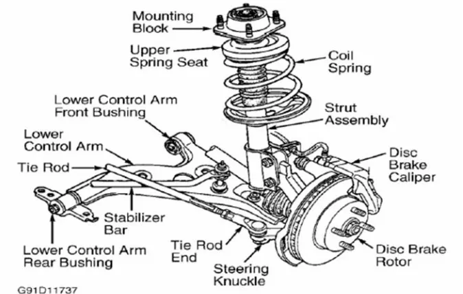
8
Figure 2.1 MacPherson suspension system (Jagwinder Singh et.al, 2015)
It was structurally built up with a substantial compression link stabilized by a secondary link with lower control arm which was mounted at the bottom to the hub or axle of the wheel as shown in Figure 2.1. The lower arm system contributed to both lateral and longitudinal movement of the wheel (A.Purushotham, 2013).
9
The Macpherson strut will eventually worked together with the environment experienced by the vehicle. In accordingly to Dave Garza et al. (2011), when a wheel hit on the road disturbance especially a road hump, the wheel and suspension strut will trigger an upward motion and leading the spring coil to be compressed. The coil spring performed in a way to sustain an appropriate suspension ride height and control suspension travel in drive. Then, shock absorber moved together with the spring coil to monitor the spring action of being compressed or tensioned. Once the spring was compressed, an elastic potential energy was stored in where latterly immediate released to extend the spring in the same proportion of energy. It resulting in the lower strut chamber to be forced downwards. The upper and lower control arm bushings were the ones which provided a free vertical movement of the control arm and to absorb the unwanted vibrations and wheel impacts. The strut was supported by a stabilizer bar to minimize the body sway during and after passing the hump. When the vehicle about to cornering or turning (steering wheel was turned), the pivoted arms were to shifted inward and forward to the body chassis to ensure the wheel remained upright besides resisting the braking and accelerating forces. The entire assembly simply as that simple to be constructed into a unit, removing the upper control arm, thus providing more significant spacing for the engine compartment (Prof. S.C.Jain et al., 2014).