© 2017, IRJET | Impact Factor value: 6.171 | ISO 9001:2008 Certified Journal
| Page 464
Power Generation by Using Suspension System
Himanshu S. Rewatkar
1, Vicky R. Gedekar
2, Kunal L. Parate
31,2,3
UG scholar, Department of Mechanical Engineering, G.H. Raisoni College of Engineering,
Nagpur, Maharashtra, India.
---***---Abstract -
The main objective of designed the controller fora vehicle suspension system is to reduce the discomfort sensed by passengers which arises from road roughness and to increase the ride handling associated with the pitching and rolling movements. This necessitates a very fast and accurate controller to meet as much control objectives, as possible. Therefore, this paper deals with an artificial intelligence Neuro-Fuzzy (NF) technique to design a robust controller to meet the control objectives. The advantage of this controller is that it can handle the nonlinearities faster than other conventional controllers. The approach of the proposed controller is to minimize the vibrations on each corner of vehicle by supplying control forces to suspension system when travelling on rough road. The other purpose for using the NF controller for vehicle model is to reduce the body inclinations that are made during intensive manoeuvres including braking and cornering. A full vehicle nonlinear active suspension system is introduced and tested. The results show that the intelligent NF controller has improved the dynamic response measured by decreasing the cost function.
Key Words: Full vehicle, nonlinear active suspension system, control design.
1. INTRODUCTION
It was described to develop electricity using the real-time motion of parts in a form of wheeler. After careful analysis of a various such parts it was decided to generated electricity using relational motion available in a suspension system of a two wheeler.
In the new age of the electric bikes, almost everything has to be modified. In one hundred years, people will launch at today's hybrid and pure electric vehicles rather in the way we launch at motor vehicles from 1880 that looked like something dragged along by a horse because that was the starting point. Inside and out, today's electric vehicles look almost the same as what went before.
We have batteries and electrical and electronic controls in big lumps because that is what they had to look like in the past, together with masses of wiring. We have a big lump of noisy, dirty, shaking internal combustion engine in a hybrid because that is what an engine has looked like in the past. Bring in smart electronic surfaces, wireless links, laminar conformal batteries and mini turbine range extenders. Then we really will have moved on in cost, performance and passenger safety, comfort and space available.
However, until we figure out how to make comfortable vehicle bodies we shall need shock absorbers, so they might as well generate electricity.
In 2005, David Oxen reider of Boiling Springs, PA, presented a design for an electricity generating shock absorber. Experimental Bosch suspension systems have generated electricity. Problems have included the devices being too large, too expensive, and too inefficient in converting electricity or just poor shock absorbers because they dispensed with the spring or had the wrong damping characteristics.
1.1 Selection of Project
We the group of young engineers found that, there is an impending need to make much more forays to make Non-Conventional energy attain popular acclaim. This is also very essential to preserve the conventional sources of energy and explore viable alternatives like sustainable energy (the energy which we are already utilizing but for some safety of other uses we are suddenly wasting it, that can be reutilized), solar, wind and biomass that can enhance sustainable growth. What is more, such alternatives are environment friendly and easily replenish able. Therefore, they need to be thoroughly exploited with a functionally expedient, energy matrix mix. Growing economies, especially of Asia are gifted with sufficient resource base and non-conventional energy technologies are consistent both for grid linked energy generation and transmission in out of the way locales that are islanded from the grid. Adaptation of technology and employing them should be pursued right from this moment to have a head start, be informed of the barriers in technology applications of the renewable variety and synergizing them with the existing, traditional power production technology. It is known that in coming times, wind energy will be the most cost-effective renewable resource. Yet, it is doubtful if any individual technology would hold center-stage. Thus we selected kinetic motors means the “Energy in motion when it is suddenly applied with a sort of obstacle, then according to Newton’s law for every action there is an equal and opposite reaction. Utilization of this reaction is the basic reason behind the selection of this project work.”
2. LITRATURE REVIEW
2.1 Introduction
© 2017, IRJET | Impact Factor value: 6.171 | ISO 9001:2008 Certified Journal
| Page 465
do. So by doing the literature review we can gain knowledgeto make sure we fully understand and can complete the project. A review of the article was performing to identify studies that relevant to the topic.
2.2 Electromagnetic Suspension System
The first method is, which works on the principle of Faraday’s law of electromagnetic induction. The shock absorber consists of two tube-like components where a smaller magnetic tube slides inside a larger, hollow coil tube. The coil component is made of copper coils wound around a plastic tube, while the magnetic component is made of ring-shaped magnets separated by ring-ring-shaped magnetically permeable spacers.
2.3 Regenerative Suspension System
The second method is, in which converts linear motion in to rotary motion. The rotational power is stored in flywheel & flywheel rotates dynamo, which generates electricity. When vehicles move on speed breaker rack will be reciprocate. The rack is attached with pinion that rotates in one direction only. The rack & pinion arrangement convert linear motion in to rotary motion. This rotary motion is further magnified using chain drive. The output of free wheel is attached with flywheel which stores kinetic energy and transfer to dynamo which generate electricity.
3. DESIGN DETAILS
3.1 Components
4. CONSTRUCTION AND WORKING OF POWER
GENERATION SUSPENSION SYSTEM FOR TWO
WHEELER
4.1 Construction
It consist of two plates of iron sheet, two plates of wooden sheet i.e. plywood, eight studs rod are used in it and four motors. First horizontal plate and fourth horizontal plate is made up iron sheet of 95mm x 95mm having 5mm thick is fabricated. The second horizontal plate and the third horizontal plate of 95mm x 95mm having 10mm thickness are made up of plywood sheet are fabricated. There are eight vertical stud rods of 5mm in diameter and 250mm length.
The first horizontal plate and third horizontal plates are connected to each other passing through second horizontal plate with the help of four stud rods and the forth horizontal plate and second horizontal plate are connected to each other passing through third horizontal plate with the help of other four stud rods.
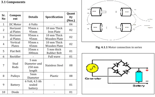
[image:2.595.32.556.426.754.2]The rubber belt flat type is fixed on the second plate and forth plate with the help of nut and bolt. On the third horizontal plate two vertical plates are mounted of 95mm x 45mm having 10 mm thickness made up of plywood sheet. Four motors are mounted on the two vertical plywood plates. These motors are connected in series to each other with Full wave Rectifier Bridge.
Fig. 4.1.1 Motor connection in series
Fig. .4.1.2 Circuit Diagram Sr.
No Component Details Specification
Quant ity (Nos.)
1 DC Motor 6 Volts - 04
2 Horizontal Plates 95mm x 95mm 10 mm Thick Iron Plate 02
3 Horizontal Plates 95mm x 95mm Wooden Plate 10 mm Thick 02
4 Vertical Plates 95mm x 45mm Wooden Plate 10 mm Thick 02
5 Flat Belt 35mm x 300mm Rubber Belt 5 mm thick 01
6 Rectifier - Full wave 01
7 Rods Stud
5 mm Diameter and
250 mm length
Stainless Steel 08
8 Pulleys Diameter 5mm Plastic 08
9 Battery 6 Volt, 4.5 Ah sealed
battery - 01
© 2017, IRJET | Impact Factor value: 6.171 | ISO 9001:2008 Certified Journal
| Page 466
Fig. 4.1.3. Construction of suspension system4.2 Working of Project
In this project we have to develop a suspension energy generation unit by using belt and pulley
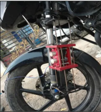
[image:3.595.49.324.65.279.2]Here, when the vehicle suspension works, the linear motion of the suspension creates friction between the pulleys and the belt. Due to this, the pulley starts rotating. The pulleys are mounted on the shaft of the DC motors. As the pulleys get rotated the shaft of the motors also get rotated which generate electricity. The figure shows the implementation of the project and its working therein. As the vehicle passes over an uneven road surface, there is relative motion of the individual wheels. As shown, the linear motion of the wheels causes the suspension to compress and this imparts motion to the belt which is attached to the wheel assembly. This in turn gives rotational motion to the pulley as shown in the highlighted area. The belt then transfers the rotary motion through pulley to the DC motors. The motors generates electricity which is the given to the various auxiliaries of the vehicle. The project assembly thus includes one front wheel, suspension and the designed units attached to it.
[image:3.595.309.547.312.523.2]Fig.4.2.1 Suspension system mounted on vehicle
Fig: 4.2.2 Suspension in normal condition
Fig: 4.2.3 Suspension in working condition
4.3 Model Calculations
Electrical Calculation
When a vehicle is running at a speed of 20 to 30 km/hr we observe 6 to 9 volts with the help of multi meter.
Voltage Generated (V) = 9 volt Current Generated (I) = 3.2 amp
As Electrical Power (P) = V x I = 9 x 3.2 = 28.8 Watts
TO CALCULATE CHARGING TIME FOR 6 VOLT BATTERY
Charging time =battery current (Ah) / current generated (A) =4.5 (Ah) /3.2(A)
= 1.40 hr
But it was noted that during charging 40% get loss =4.5 x 40 /100
[image:3.595.73.237.578.761.2]© 2017, IRJET | Impact Factor value: 6.171 | ISO 9001:2008 Certified Journal
| Page 467
To charge a 6 volt battery with this suspension including40% loss we can charge the battery with 1.9 hr.
TO CALCULATE CHARGING TIME FOR 12 VOLT BATTERY
Consider that the suspension system is mounted on both side of the front suspension.
Total voltage produced by this suspension system in 18 volt, 64A
Therefore time required to charge a 12 volt, 33 Ah battery is, Charging Time =Battery current (Ah) / current generated (A)
=33 (Ah)/ 6.4 (A) =5.15 hr
But it was noted that 40% loss during battery charging =33 x 40/100
=13.2 (Ah)
Charging time = 33 + 13.2 /6.4 =7.21 hr
4. RESULT
4.1 Estimation Cost
4.2 Advantages and Disadvantages
4.2.1 Advantages
Shock absorbers have a great for performance, handling and stability.
They are best choice for work and severe use vehicles.
High pressure gas mono tube design- 360psi to prevent aeration and shock fade.
Low pressure gas twin tube design- These units are good for average, everyday driving.
4.2.1 Dis-advantages
Not applicable for all types of two wheelers. On smooth road power generation is less than 4
volt.
Design of the suspension system not suitable for scooter.
As whole system consist of electric wiring, so that chances of short circuits.
Conventionally, the vibration energy of vehicle suspension is dissipated as heat by shock absorber, which wastes a considerable number of resources. Power Generating by Shock Absorber brings hope for recycling the wasted energy. All types of Power Generating Shock Absorber, especially electromagnetic suspension, and their properties are reviewed in this project. From the perspective of comprehensive performance including vibration control ability, regenerative efficiency and application reliability. With improvement of technology, Power Generating Shock Absorber may become one of promising trends of vehicle industry.
5.2 Future scope
The scope for this project is that it is simple in construction and design and has low in price. It is easily mounted on the chassis of the vehicle and it produced 2 to 3 volts in even road and 6 to 9 volts on uneven rod which is sufficient for charging the vehicle battery when the vehicle is in a running position. This increases the efficiency of electric vehicles up to 10%. Further improvement in the suspension design makes it suitable for any two wheelers (electric). By increasing the no. of DC motor generation of power get increases which are used to charge high voltage battery. This system can be used on to the mono suspension system by making suitable design. By modifying this system we can implement this on to the electric car
Sr.
No Component Unit Cost (Rs.) Quality (Nos.) Cost (Rs,)
1 Horizontal Plates 100 4 400
2 Rectifier 5 1 5
3 Stud Rods 8 10 80
4 DC motor 130 4 520
5 Belt 20 1 20
6 Paint 25 2 50
7 Welding 150 - 150
8 Wire 10 - 10
9 Pulley 5 8 40
10 Nut and Bolt 50 - 50
11 Battery 230 1 230
12 Diode 2 1 2
Total 1557.00 Rs.
5. CONCLUSION & FUTURE SCOPE
© 2017, IRJET | Impact Factor value: 6.171 | ISO 9001:2008 Certified Journal
| Page 468
6. REFERENCES
[1] Arekar, M.P. and Shahade, S. (2015). Power Generating Shock Absorber. International Journal of Innovative Research in Science, Engineering and Technology, Volume 4, Issue 3: 169-178
[2] International Journal of Engineering Technology, Management and Applied Sciences www.ijetmas.com March 2015, Volume 3 Issue 3, ISSN 2349-4476
[3] International Journal of Pure and Applied Research in Engineering and Technology, Research Article Impact Factor: 0.621 ISSN: 2319-507X Swapnil Kamthe, IJPRET, 2014; Volume 2 (9): 169-178 IJPRET
[4] Proceedings of the World Congress on Engineering 2013 Vol III, WCE 2013, July 3 - 5, 2013, London, U.K.
[5] International Journal of Engineering Science and Innovative Technology (IJESIT) Volume 3, Issue 4, July 2014