Recent Advances in Measuring and Understanding the Influence of Molecular
Alignment on the Light Extraction Efficiency of OLEDs
Caroline Murawski, Arko Graf, Philipp Liehm, Ana Neferu,
Eli Zysman-Colman, Malte C. Gather
Organic Semiconductor Centre, SUPA School of Physics and Astronomy and EaStCHEM School of Chemistry, University of St Andrews, North Haugh, St Andrews, United Kingdom
Abstract
We review recent progress in controlling the alignment of the transition dipole moment of electroluminescent molecules to maximize the light extraction efficiency in OLEDs. Particular focus devoted to ways of measuring molecular orientation and on linking molecular structure to alignment.
Author Keywords
Introduction
Organic light-emitting diodes (OLEDs) are light sources in which the light is generated by an ultrathin (few tens of nm) transparent film consisting of organic molecules and/or organometallic complexes. Under electrical or optical excitation, the excited molecules emit light, homogeneously and continuously across the whole layer. OLEDs can be produced from solution, e.g., by inkjet printing, or via evaporation under high vacuum. The technology is compatible with a wide variety of different substrate materials, including for example flexible plastic substrates, TFT backplanes and silicon CMOS chips. These unique properties render OLEDs a highly suitable technology for both displays and lightning, with a number of commercial products now in mass production for the former.
For many years, a primary focus in OLED research has been to improve the internal device efficiency, i.e. the yield of charge-to-photon conversion. In many state-of-the-art devices today, however, this is achieved with near unity efficiency, mostly thanks to the development of triplet harvesting[1–3], doped charge transport layers[4,5], and efficient
charge blocking structures[6]. The focus has therefore now moved to improving the efficiency of outcoupling, i.e.
enhancing the fraction of the generated photons that escape from the OLED into the surrounding air. Despite good progress, outcoupling remains a major loss channel, with < 30% of the photons being extracted from typical OLEDs. Developing efficient approaches to light extraction that can be readily applied in a display fab setting remains a major challenge for the community[7].
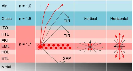
[image:2.612.191.424.468.592.2]Among the approaches currently considered to enhance outcoupling, the use of oriented emitter molecules is receiving special attention because it promises to enhance light extraction through materials design and thus without increasing the complexity of the device. The influence of emitter orientation on outcoupling efficiency in OLEDs becomes clear when one analyzes the two main loss mechanisms involved in the outcoupling of light from an OLED: total internal reflection (TIR) leads to trapping of light in waveguided modes and the excitation of surface plasmons confines and ‘dumps’ light at any metallic electrodes (Figure 1). Both of these processes are absent for light that is emitted directly the forward direction, i.e. at normal incidence with respect to planar surfaces. Since the emission of each emitter molecule can be described as a radiative dipole, their orientation strongly affects the amount of light lost within the planar structure of the OLED.
Figure 1 illustrates the outcoupling of light from an OLED for radiative dipoles that have either a horizontally or a vertically oriented transition dipole moment. Horizontal orientation is desirable since in this case the maximum power is dissipated in the forward direction and hence the emitted light can be extracted efficiently. Simulations show that by moving from isotropically, i.e. randomly, oriented emitter molecules to completely horizontally aligned molecules, one can increase the OLED efficiency by a factor of 1.5[7].
For OLEDs based on polymeric materials, the long and pseudo-rigid shape of the polymer, combined with the fact that the transition dipole moments of polymers tend to be aligned along the polymer chain[10], means that preferential
horizontal dipole orientation is frequently obtained for these materials. By contrast, it was originally assumed that outcoupling enhancement due to oriented emissive dipoles cannot be harnessed for small molecule based OLEDs because these were believed to generally show an isotropic orientation. However, Yokoyama et al. showed that linear-shaped small molecules with suitable substituents can spontaneously align within a neat thin film that is deposited by thermal evaporation under high vacuum and it was then hypothesized that this alignment may yield substantial improvements in efficiency [11]. Subsequently, Flämmich et al. proposed a more accurate method to
measure the orientation of emissive dipoles in electrically driven OLEDs[12] and Frischeisen et al. found that in
fluorescent, small molecule OLEDs horizontal emitter orientation can increase the outcoupling efficiency substantially[13].
While these first works were based on elongated fluorescent emitter molecules, it is less obvious that phosphorescent emitter complexes, which tend to have a more spherical molecular structure, can also show preferred molecular orientation. Over the past five years, however, there has been extensive research into this questions by us[14–16] and many others (e.g., Ref. [9,17–20]) and a number of interesting insights were gained from this.
The following reviews the work originally published in Ref. [14–16].
Measuring transition dipole orientation
One of the strategies that have been used to determine the average orientation of the transition dipole moments of emissive molecules is to perform angle-resolved photoluminescence spectroscopy on thin films of the material in question and compare against optical simulations. An extension of this approach is to record and analyze angle-resolved electroluminescence from complete OLED stacks. Working with complete OLEDs and using electrical rather than optical excitation ensures that one measures the average orientation of the emitter molecules involved in the actual emission process and thus excludes possible artifacts; however, this comes at the cost of additional complexity of the measurement and is restricted to measuring OLEDs with sufficient stability as required to prevent changes in brightness or spectrum during the measurement.
The emissive molecules in an OLED or an optically excited thin film of emitter molecules can be described as a superposition of the contribution from horizontally (h) and vertically (v) aligned dipoles. The overall emission from the structure into the far-field medium is described by the spectral radiant intensity and can therefore be written as
𝐼(𝜃, 𝜆, 𝑎) = 𝑎 𝐼𝑇𝑀,𝑣+ (1 − 𝑎)(𝐼𝑇𝑀,ℎ+ 𝐼𝑇𝐸,ℎ). (1)
Here, TM (transverse magnetic) and TE (transverse electric) indicate the polarization of the emitted light. θ is viewing angle, λ the wavelength and a is the anisotropy factor, i.e. the ratio of the number of vertical dipoles to the total number of dipoles, which describes the average orientation of the transition dipole moment. Isotropic orientation (a = 1/3) is present if 1/3 of the transition dipole moments are aligned perpendicular to the planar surface, i.e. vertically oriented, and 2/3 are aligned parallel to the planar surface horizontally oriented. Optical simulations show that maximum outcoupling efficiency is achieved for a = 0, in other words complete horizontal alignment of all transition dipole moments.[12]
The anisotropy factor a is determined by performing a least-squares fit to measured spectral radiant intensity with data obtained from an optical simulation using a as a fitting parameter. The optical simulations are based on a well-established transfer matrix approach combined with an electromagnetic dipole model.[21] Analysis of Equation (1)
shows that I(θ,λ,a)is most sensitive to a if an equal amount of light is emitted by horizontally and vertically aligned dipoles. As discussed above, vertically oriented dipoles normally contribute very weakly to the overall emission. Therefore, this requirement is best fulfilled by an OLED stack that is designed for the first optical minimum, i.e. where light emission from horizontally aligned dipoles is suppressed by destructive interference between direct emission and light reflected from the back cathode. To enhance the sensitivity further one can filter out the ITE,h
metal cathode and the EML strongly affect I(θ,λ,a).[22] In many small molecule OLEDs, this distance essentially
corresponds to the thickness of the electron transport layer (ETL), which is thus added as a second fitting parameter for each device.
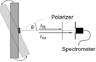
[image:4.612.220.403.151.269.2]A setup that can be used to measure the polarization resolved electroluminescence spectra of each OLED as a function of viewing angle θ is schematically illustrated in Figure 2. The OLED is mounted on a goniometer and emission is collected through a polarizer by a fiber-coupled spectrometer.
Figure 2. Sketch of a setup for measuring angle-resolved spectral radiant intensity. The OLED to be investigated is mounted on a goniometer and emission is collected through a polarizer by a fiber-coupled spectrometer.
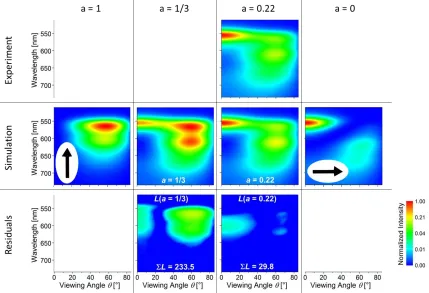
Figure 3 shows an example of normalized experimental and simulated I(θ,λ,a) data for a phosphorescent OLED. For this example, the least-squares optimization yields an anisotropy factor of a = 0.22 and a good agreement between simulated and experimental data is observed for this value. Simulations assuming isotropic or even fully vertical orientation predict significantly lower emission intensity in the forward direction, i.e. at θ = 0°. A simulation assuming perfectly horizontal orientation underestimates the emission intensity at higher angles.
To investigate the results more closely, one can look at the residuals versus angle and wavelength, i.e. the square of the difference between the experimental and simulated spectral radiant intensity for each data point:
𝐿(𝜃, 𝜆, 𝑎) = (𝐼𝐸𝑥𝑝(𝜃, 𝜆, 𝑎) − 𝐼𝑇𝑀𝑆𝑖𝑚(𝜃, 𝜆, 𝑎))
2
. (2)
The data in Figure 3 show that the deviation between simulation and experiment remains at L(θ,λ,a) < 0.04 from all wavelength and angles for a = 0.22, whereas much larger deviations are observed if one falsely assumes a = 0.33.
Alternative means to determine and study the orientation of the transition dipole moment are to record either the decay rate of emission following a brief electrical or optical excitation pulse or to investigate the dependence of the roll-off in external quantum efficiency (EQE) with increasing current density[16]. While we have found the latter to
yield results consistent with both angle-resolved and time-resolved measurement, particular care has to be taken to exclude other factors that may influence the EQE roll-off.
Examples of molecular orientation
Wang et al. reported on a very efficient and simple OLED stack based on Ir(ppy)2(acac) embedded in a CBP
matrix[23]. To better understand why this structure yields such high efficiency while a similar structure based on the
similar emitter fac-Ir(ppy)3 is considerably less efficient we carried out combined EQE and orientation studies[14].
In our lab, optimized OLEDs based on these emitters achieved external quantum efficiencies of 18.3% using fac -Ir(ppy)3 and 21.7% using Ir(ppy)2(acac),as the respective emitters. We found that the anisotropy factors of
Ir(ppy)2(acac) and fac-Ir(ppy)3 are 0.23 and 0.31, respectively, i.e. while the transition dipole moment of fac-Ir(ppy)3
shows virtually no preferential alignment, for Ir(ppy)2(acac) the transition dipole moment has a preferential
Ir(ppy)2(acac) relative to fac-Ir(ppy)3 devices. However, it appears that the internal efficiency of the Ir(ppy)2(acac)
based devices is also slightly higher, presumably as a result of reduced aggregation of emitter molecules[24].
In a later study, we explored and compared the orientation of seven phosphorescent emitter complexes commonly used in OLEDs: the three facial homoleptic compounds Ir(ppy)3 (green), Ir(chpy)3 (yellow-green), and Ir(piq)3 (red),
as well as the four heteroleptic molecules with one non-chromophoric acetylacetonate (acac) ligand, namely Ir(ppy)2(acac) (green), Ir(dhfpy)2(acac) (yellow), Ir(BT)2(acac) (orange), and Ir(MDQ)2(acac) (orange-red)[15].
Surprisingly, we found that among the molecules studied, Ir(ppy)3 was the only emitter with isotropically distributed
transition dipole moments and that the transition dipole moments of the other homoleptic compounds shows a pronounced anisotropy. To correlate our results to the molecular properties, we calculated the permanent dipole moment and the size of the molecules by density functional theory (DFT). From this we identified the dipole-dipole potential of phosphorescent emitters as a parameter that may be strongly correlated with transition dipole orientation.
We have also looked at the influence of emitter orientation on triplet-triplet annihilation and on the efficiency roll-off of phosphorescent OLEDs[16]. For this study, we systematically varied the distance of the emitter molecules
from the reflective metal cathode of OLEDs based on two different Ir-based emitters [Ir(MDQ)2(acac) and Ir(ppy)3]
in order to investigate the influence of the optical environment on the efficiency roll-off. A clearly different behavior was observed for Ir(MDQ)2(acac) and Ir(ppy)3. By performing time-resolved electroluminescence measurements
[image:5.612.92.521.98.391.2]and detailed optical modeling of our OLEDs, we were able to correlate these differences to the different orientation of the transition dipole moments of these two types of emitters. OLEDs based on Ir(ppy)3, which is oriented
Figure 3. Maps of spectral radiant intensity of a phosphorescent OLED. Experimental data is compared to simulations for anisotropy factors of a = 1 (fully vertical), 1/3 (isotropic), 0.22 (preferentially horizontal), and 0 (fully horizontal). Also shown is point-wise quadratic difference between experiment and simulations for
isotropically, showed the lowest roll-off when the emitter was positioned close to the metal cathode. Ir(MDQ)2(acac), which is instead preferentially horizontally oriented, had the lowest roll-off for emitters located
close to the first optical maximum of the electromagnetic field in the OLED. Due to the clear relation between roll-off and emitter orientation, a roll-roll-off analysis can in principle be used to perform an independent in-situ
measurement of emitter orientation. However, this requires that the contribution of roll-off mechanisms other than TTA is negligible.
Most recently, we also investigated the orientation of Ir(ppy)3 and Ir(ppy)2(acac) via grazing incidence X-ray
diffraction (GIXRD)[25]. This showed that both emitters form crystallite grains even if the emitter is doped into a
host. Further investigations via 2D grazing incidence wide-angle X-ray scattering (GIWAXS) reveal that the crystallite grains of both emitters show a preferential orientation in out-of-plane direction.
Acknowledgements
This work was funded by German BMBF under Contract No. 13N11060 (R2Flex), ESF/EU project OrganoMechanics and the European Community’s Seventh Framework Programme under Grant Agreement No. FP7 267995 (NUDEV). M.C.G. acknowledges support from European Union Marie Curie Career Integration Grant (PCIG12-GA-2012-334407). E.Z.-C. acknowledges support from the Leverhulme trust (RPG-2016-047).
References
[1] M. Baldo, D. O’Brien, Y. You, A. Shoustikov, S. Sibley, M. E. Thompson, S. R. Forrest, Nature1998, 395, 151.
[2] M. A. Baldo, S. Lamansky, P. E. Burrows, M. E. Thompson, S. R. Forrest, Appl. Phys. Lett.1999, 75, 4. [3] H. Uoyama, K. Goushi, K. Shizu, H. Nomura, C. Adachi, Nature2012, 492, 234.
[4] G. He, M. Pfeiffer, K. Leo, M. Hofmann, J. Birnstock, R. Pudzich, J. Salbeck, Appl. Phys. Lett.2004, 85, 3911.
[5] K. Walzer, B. Maennig, M. Pfeiffer, K. Leo, Chem. Rev.2007, 107, 1233. [6] C. W. Tang, S. a. VanSlyke, Appl. Phys. Lett.1987, 51, 913.
[7] M. C. Gather, S. Reineke, J. Photonics Energy2015, 5, 57607.
[8] S.-Y. Kim, W.-I. Jeong, C. Mayr, Y.-S. Park, K.-H. Kim, J.-H. Lee, C.-K. Moon, W. Brütting, J.-J. Kim,
Adv. Funct. Mater.2013, 23, 3896.
[9] K.-H. Kim, S. Lee, C.-K. Moon, S.-Y. Kim, Y.-S. Park, J.-H. Lee, J. Woo Lee, J. Huh, Y. You, J.-J. Kim,
Nat. Commun.2014, 5, 4769.
[10] M. C. Gather, D. D. C. Bradley, Adv. Funct. Mater.2007, 17, 479.
[11] D. Yokoyama, A. Sakaguchi, M. Suzuki, C. Adachi, Org. Electron.2009, 10, 127.
[12] M. Flämmich, M. C. Gather, N. Danz, D. Michaelis, A. H. Bräuer, K. Meerholz, A. Tünnermann, Org. Electron.2010, 11, 1039.
[13] J. Frischeisen, D. Yokoyama, A. Endo, C. Adachi, W. Brütting, Org. Electron.2011, 12, 809.
[14] P. Liehm, C. Murawski, M. Furno, B. Lüssem, K. Leo, M. C. Gather, Appl. Phys. Lett.2012, 101, 253304. [15] A. Graf, P. Liehm, C. Murawski, S. Hofmann, K. Leo, M. C. Gather, J. Mater. Chem. C2014, 2, 10298. [16] C. Murawski, P. Liehm, K. Leo, M. C. Gather, Adv. Funct. Mater.2014, 24, 1117.
[17] M. Flämmich, J. Frischeisen, D. S. Setz, D. Michaelis, B. C. Krummacher, T. D. Schmidt, W. Brütting, N. Danz, Org. Electron.2011, 12, 1663.
[18] T. D. Schmidt, D. S. Setz, M. Flämmich, J. Frischeisen, D. Michaelis, B. C. Krummacher, N. Danz, W. Brütting, Appl. Phys. Lett.2011, 99, 163302.
[19] K. H. Kim, C. K. Moon, J. H. Lee, S. Y. Kim, J. J. Kim, Adv. Mater.2014, 26, 3844.
2016, 15, 85.
[21] M. Furno, R. Meerheim, S. Hofmann, B. Lüssem, K. Leo, Phys. Rev. B2012, 85, 115205.
[22] M. C. Gather, M. Flämmich, N. Danz, D. Michaelis, K. Meerholz, Appl. Phys. Lett.2009, 94, 263301. [23] Z. B. Wang, M. G. Helander, J. Qiu, D. P. Puzzo, M. T. Greiner, Z. M. Hudson, S. Wang, Z. W. Liu, Z. H.
Lu, Nat. Photonics2011, 5, 753.
[24] S. Reineke, T. C. Rosenow, B. Lüssem, K. Leo, Adv. Mater.2010, 22, 3189.
[25] C. Murawski, C. Elschner, S. Lenk, S. Reineke, M. C. Gather, in OSA Tech. Dig. -Light, Energy Environ.,