promoting access to White Rose research papers
White Rose Research Online [email protected]
Universities of Leeds, Sheffield and York
http://eprints.whiterose.ac.uk/
This is an author produced version of a paper published in International Journal of Machine Tools and Manufacture.
White Rose Research Online URL for this paper:
Published paper
Yusoff, A.R., Sims, N.D. (2011) Optimisation of variable helix tool geometry for regenerative chatter mitigation, International Journal of Machine Tools and Manufacture, 51 (2), pp. 133-141
Optimisation of variable helix tool geometry for regenerative
chatter mitigation
Ahmad R Yusoffa,b,∗
, Neil D Simsb,∗∗
a
Faculty of Mechanical Engineering, Universiti Malaysia Pahang, Pekan Campus, 26 600 Pekan, Pahang, Malaysia
b
Department of Mechanical Engineering, The University of Sheffield, Mappin Street, Sheffield, S1 3JD, UK
Abstract
It is well known that regenerative chatter can result in excessive tool wear, poor surface finish, and hence limited productivity during metal machining. Various mitigation methods can be applied to suppress chatter; however, the current paper focuses on applying optimal variable helix tool geometry. A semi discretrisation method is combined with Differential Evolution to optimise variable helix end milling tools so as to avoid chatter by modifying the variable helix and variable pitch tool geometry. The semi discretrisation method is first validated experimentally. The numerical optimisation procedure is then used to optimise tool geometry for a machining problem involving a flexible workpiece. The analysis pre-dicted total mitigation of chatter using the optimised variable helix milling tool at a low radial immersion. However, in practice a five fold increase in chatter stability was obtained, compared to the traditional milling tool.
Key words: regenerative chatter, variable helix, optimisation, milling
1. Introduction
High productivity of metal cutting processes in the aerospace, mould/die and automotive industries is limited by the occurrence of regenerative chatter. Chatter also causes lower machining quality, poor accuracy and surface finish, unpleasant noise and sound, accelerated tool wear, and can even damage the cutting spindle and machined part. Various approaches can be used to avoid the above catastrophic problems, such as active damping [1, 2], passive damping [3, 4], spindle speed variation [5, 6, 7] and variable pitch tools [8, 9, 10, 11, 12, 13]. The present contribution investigates an approach to chatter suppression that disrupts chatter vibration using variable helix tools. These tools possess different geometry to regular
∗Now at Faculty of Mechanical Engineering, Universiti Malaysia Pahang, Pekan Campus, 26 600 Pekan,
Pahang, Malaysia
∗∗Corresponding author
Email addresses: [email protected](Neil D Sims)
(a) (b)
β
δφ
δφ
1 δφ2
δφ3 δφ4
β β β
β
β β β
(c)
β1
β4 β3 β2
(d)
β1
β4 β3 β2
δφ δφ
δφ δφ
δφ
1 δφ2
δφ3 δφ4
δφ δφ
[image:3.595.115.479.107.412.2]δφ
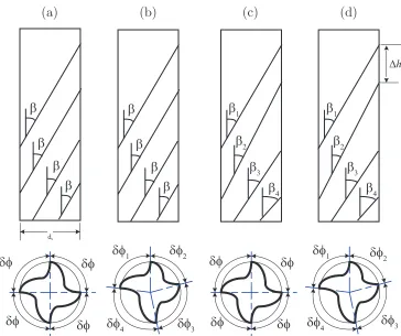
Figure 1: Variable pitch tool geometry for a 4 flute tool. (a) Regular tool - uniform pitch, uniform helix; (b) Variable pitch tool; (c) Variable helix tool - special case with regular pitch at the tool tip; (d) Variable helix tool
tools (with uniform helix and uniform pitch) or variable pitch tools, as shown in Fig. 1.
Variable pitch tools were initially proposed by Slavicek [12]. Later, Opitz et al [11] studied
irregular tooth pitches that produce a higher stable depth of cut. Variable pitch tools were
re-considered by Altintaset al [8] who utilised an invariant time constant and a non uniform
multiple regeneration time delay to optimise pitch geometry. Meanwhile, Budak [9] modelled and optimised a non constant pitch tool. Recently, Olgac and Sipahi [10] maximised the material removal rate in simultaneous machining by applying an irregular pitch cutter that was optimised using the ‘cluster treatment of characteristic roots’ approach.
Variable helix tools have often been disregarded in previous research for suppressing
chatter. To the authors’ knowledge, only Stone [13] and Turneret al [14] considered variable
helix milling tools in their studies. Simset al [15] modelled variable helix and variable pitch
milling tools using a Semi-Discrete Method (SDM). However, they only predicted the chatter stability, and did not optimise the tool design for minimising chatter. Furthermore they did not perform their own experimental validation of the modelling approach.
tools. An experimental study is first conducted to validate the modelling procedure. An optimisation method is then developed so that the variable helix geometry can be chosen to avoid chatter of a flexible workpiece. The optimisation approach is based upon a Differential Evolution (DE) strategy. The optimal tool geometry is then used to fabricate a custom-built variable pitch milling tool, and the experimental performance of this tool is compared to a regular tool geometry. Following a discussion some conclusions are drawn regarding the potential benefits of optimised variable helix tools.
2. Variable helix modelling and validation
Before considering the optimisation of variable helix tools, the chosen chatter prediction method (semi discretisation method, or SDM) is briefly described and its performance is validated experimentally.
2.1. Semi discretisation method
The Semi Discretisation Method (SDM) is a well known technique for analysing the stability of linear retarded dynamical systems. The effects of time delays and time periodicity are considered to produce a high dimensional linear discrete system. Details of SDM are
given in [16]. Recently, Sims et al [15] applied SDM to model irregular helix and pitch
tools. They showed that in order to account for a variable helix on a tool, the stability must be considered for one complete tool rotation period, rather than one tooth-passing period. Furthermore, this work demonstrated that the SDM must be recast in a state-space formulation in order to allow for variable helix geometry. This approach will be used in the present study and so for completeness the SDM modelling procedure is now briefly summarised.
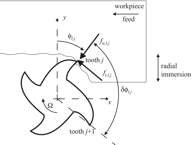
Consider the schematic representation of milling shown in Fig. 2. Here, an axial layer l
of the tool is considered, with toothj engaged in the workpiece. The resulting cutting forces
in the normal (fn,l,j) and tangential (ft,l,j) directions are shown, and these are assumed to
be proportional to the chip thickness h and depth of cut b. These cutting forces can be
summed for all teeth on the tool, and all axial layers of the tool up to the axial depth of
cut. These forces can be expressed as resultant forces Fx and Fy in the x and y directions
respectively.
These forces act to cause relative vibration between the tool and workpiece, due to the structural dynamics of the system. These flexible components could be the cutting tool, workpiece, or the machine-tool structure. The relative vibrations cause a change in the
instantaneous chip thickness h of the teeth engaged in the workpiece. This results in a
feedback process that is illustrated by the block diagram shown in Fig. 3.
Discretising the continuous time structural dynamics gives the following state-space rep-resentation:
xm(kT +T) =Amxm(kT) +Bm
Fx(kT)
Fy(kT)
ux(kT)
uy(kT)
=Csxm(kT)
fn,l,j
toothj
x y
workpiece
radial immersion
toothj+1
φl,j
δφl,j
ft,l,j
Ω
[image:5.595.139.458.111.352.2]feed
Figure 2: Schematic representation of cutting forces during milling
Figure 3: Block diagram of forces and displacements during milling
whereAm and Bm are given by the matrix exponential:
[Am][D×D] [Bm][D×2]
− −
[(D+2)×(D+2)]
= exp
T
[As][D×D] [Bs][2×D]
[0][2×D] [0][2×2]
(2)
In Eq. (1) and (2), As, Bs, and Cs define the continuous time structural dynamics (with
D states) in state space form, and T is the sampling time used for discretrisation. This is
chosen so that there are an integral numberN of samples per tool revolution. With reference
to Fig. 2, the use of a variable helix tool means that the pitch δφl,j of the flutes changes
on each layer l. In [15] this was handled by defining the so-called ‘delay states’ ∆, which
represent the difference between the current discrete-time displacements and theN previous
[image:5.595.185.409.390.491.2]vibrationu and the delay state ∆ can be represented in discrete-time state-space form as:
xd(kT +T) =Adxd(kT) +Bd
ux(kT)
uy(kT)
∆x(kT)
∆y(kT)
=Cdxd(kT) +Dd
ux(kT)
uy(kT)
(3)
The terms in Eq. (3) are given in the Appendix. Finally, the cutting forces can be related
to ∆ by the time-periodic matrix coefficient R:
Fx(kT)
Fy(kT)
=R(nT)
∆x(kT)
∆y(kT)
(4)
The schematic block diagram shown in Fig. 3 can now be replaced by a mathematical model by combining Eq. (1), (2), and (3) to give:
xm(kT +T)
xd(kT +T)
=A
xm(kT)
xd(kT)
+BC(nT)
xm(kT)
xd(kT)
(5)
where:
A=
Am [0]
BdCs Ad
B=
Bm
[0][2N×2]
C(nT) =
R(nT)DdCs R(nT)Cs
(6)
Consequently the states of the system vary between one tool revolution and the next tool revolution as follows:
xm(kT +N T)
xd(kT +N T)
= (A+BC(N T)) (A+BC((N −1)T)) (. . .) (A+BC(T))
xm(kT)
xd(kT)
(7) The asymptotic stability of the system is therefore governed by the eigenvalues or
characteris-tic multipliers of (A+BC(N T)) (A+BC((N −1)T)) (. . .) (A+BC(T)). Characteristic
Multipliers (CMs) with magnitude less than unity indicate a stable system, and the type of instability can be determined by the location at which the CM crosses the unit circle in the marginally stable condition [17].
Complex-valued CMs of unity magnitude are associated with a secondary Hopf bifurca-tion, which lead to quasi-periodic behaviour where the chatter frequency differs from the forced vibration frequency (due to tool rotation). This is the most common form of chatter instability.
Natural frequency (Hz) 200
Modal effective mass (kg) 1.41
Damping Ratio 0.0078
Table 1: Modal parameters of thexdirection mode of vibration of the flexible workpiece
Finally, a CM equal to +1 is associated with a cyclic fold bifurcation, where the chatter frequency equals the forced vibration frequency. This form of instability has not been commonly observed during milling experiments or milling chatter predictions.
2.2. Experimental validation
In previous work [15], this modelling procedure was described in detail, and confidence in the stability predictions was improved by comparing the model to previously published experimental data for regular pitch tools and variable pitch tools. For variable helix tools, the model predictions were compared to time domain simulations. The aim of the present section is to perform experimental validation of the model’s predictions.
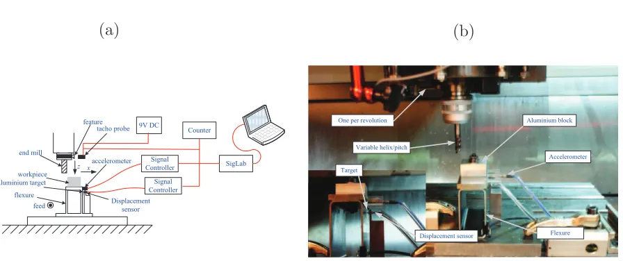
The experiments were conducted on a Mori Seiki SV500 3 axis CNC vertical milling
machine. A four-flute variable helix (37◦
, 40◦
, 37◦
, 40◦
) and variable pitch (78.4◦
, 80.4◦
, 78.4◦
, 80.4◦
) commercially available 12 mm diameter milling tool was used in present study. It was used to down-mill (at 5 percent radial immersion) an aluminium 7075-T6 block mounted on a flexible support that could be modelled as a single-degree-of-freedom system.
The cutting stiffness of the tool/workpiece was estimated to be Kn= 283 MN/m2 and Kt=
143 MN/m2 and the structural dynamics of the flexible workpiece are shown in Table 1.
The experimental configuration is shown in Fig. 4. An eddy-current displacement sensor signal was used to measure the onset of chatter vibrations. A pulse signal produced from a hall-effect probe monitoring the milling spindle was to produce once-per-revolution samples of the eddy-current measurement. The response of the system could be then analysed in terms of the frequency domain, the once/rev vibration samples, and the Poincar´e section in delayed coordinates.
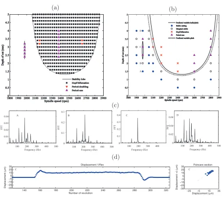
Fig. 5a illustrates the predicted chatter stability using the SDM approach. There is a large region that is associated with secondary Hopf-bifurcations, as found in classical machining chatter. However, in addition there are isolated regions of instability that arise due to period-one bifurcations. Similar behaviour was predicted in [15], where it was pointed out that the existence of period-one bifurcations has previously only been associated with tool runout [18].
(a) (b)
Figure 4: Experimental setup. (a) Schematic; (b) photograph.
stable when some portions of the test cut exhibited unstable behaviour, and some portions exhibited stable behaviour.
The most interesting feature is the isolated island of period one behaviour, labelled C in Fig. 5b. This was only predicted for a variable helix tool, and not for a variable pitch tool, as illustrated by the stability boundaries that are superimposed. This behaviour is illustrated in more detail in Fig. 5c, which shows the FRF of the displacement signal as the depth of cut increases through tests A, B, C, D. The vibration has a low amplitude non sinusoidal behaviour in cut A, but cuts B and C exhibit high amplitude vibrations at the chatter frequency. If the depth of cut is increased further (cut D) then the vibration amplitude drastically reduces and the Fourier analysis resembles that for cut A.
Fig. 5d shows the once per revolution samples and Poincar´e section of the displacement signal for cut C. This clearly illustrates the period one behaviour of the high amplitude vibrations for this test cut.
Returning to Fig. 5b, one discrepancy between prediction and experiment can be seen, namely the experimentally observed period one behaviour at higher spindle speeds (2600 -2800 rev/min). Although secondary Hopf bifurcations were expected here, the predicted stability boundary still closely matched the experimental stability boundary. The period one behaviour could be attributed to unmodelled tool runout or the closeness of the chatter frequency to the forced vibration frequency.
(a) (b)
Number of revolution
(c) (d) B A C D
140 160 180 200 220 240 260 280 300 320
−35 −25 −15 −5 5 15 25 35 D isp la ce men t ( µ m)
Displacement (µm)
D isp la ce men t + δ ( µ m) Displacement 1/Rev
−25 −5 15 35
−35 −25 −15 −5 5 15 25
35 Poincare section
C C
100 200 300 400 500
0 0.02 0.04 0.06 F F T Frequency (Hz) D
100 200 300 400
0 0.1 0.2 0.3 0.4 FF T C Frequency (Hz)
100 200 300 400 500
0 0.1 0.2 0.3 F F T B Frequency (Hz)
100 200 300 400 500
[image:9.595.71.525.189.591.2]0 0.01 0.02 0.03 0.04 F F T Frequency (Hz) A
3. Numerical Optimisation
The previous section has demonstrated the model’s ability to predict chatter stability for variable helix tools. The present section will introduce an optimisation algorithm that will allow the tool’s variable helix angles to be designed so as to avoid chatter.
3.1. Problem formulation
To begin, the optimisation problem must be posed such that potential algorithms can be employed to search for solutions. The stability analysis takes as inputs the structural dynamics of the system, the empirical cutting force coefficients, and the tool’s geometry (helix, pitch angles). For each spindle speed and depth of cut, the stability is then predicted by way of the Characteristic Multipliers, where a CM greater unity indicates instability. Consequently, the maximum CM (at any depth of cut or spindle speed) must be minimised in order to avoid chatter. In order to obtain good performance over a range of spindle speeds and depths of cut, the maximum CMs can be obtained for a range of permutations of these parameters, and then an average maximum CM obtained.
In the present study, the tool’s geometry will be considered to be input parameters that can be optimised so as to avoid chatter. Meanwhile, the structural dynamics, radial width of cut, and cutting force coefficients will be assumed to be fixed. From a practical perspective, the tool geometry must be constrained so as to only consider physically meaningful solutions. For example, the helix angles of consecutive teeth must still provide room for the chip to travel up the flute. With reference to Fig. 1, this can be encoded by introducing the variable ∆hi:
∆hi =
dc−dc(2Nc) −1
tanβi
− dc−2dc(Nc)
−1
sin (2−1
∆φi)
tanβi+1
(8)
Here, dc is the tool diameter, Nc the number of teeth, βi the helix angle for flutei, and ∆φ
the pitch between tooth i and toothi+ 1. Using this as a constraint leads to the following
definition of the optimisation problem:
Minimise mean of maximum CMs, where CM =f(βi, φi)
Subject to constraints
Helical Angle
25◦
≤βi ≤55 ◦
i= 1,2,3. . . Nc
Pitch Angle
φ+ 22.5◦
≤φi≤φ+ 22.5 ◦
i= 1,2,3. . . Nc
Helical height difference ∆hi ≥5 mm
This optimisation problem will be tackled using a Differential Evolution algorithm.
3.2. Differential Evolution procedure
Evaluation Algorithms such as Genetic Algorithm (GA), Evolutionary Programming and Evolution Strategy have been researched for several decades. Differential Evolution (DE)
was introduced by Price et al [19], and can be considered to be an improved GA version
in which mutation plays the key role, with real valued parameters that directly search for the global optimum. A basic idea in DE is that of adapting the search during the evolution process. Compared to other algorithms, DE has the advantages of simple structure, ease of use, speed and robustness. In machining applications, Saikumar and Shunmugan [20] applied DE to select the best cutting speed, feedrate and depth of cut to achieve optimum surface finish while Krishna [21] applied DE in a grinding process.
DE can solve objective functions that are non differentiable, non linear, noisy, flat, multi dimensional, and with multiple local minima. Such functions are difficult to solve analyti-cally, and the variable helix optimisation problem fits within this scope. DE begins using initial samples at multiple random chosen initial points. With simple algorithms, DE can search for the optimal condition very quickly with minimal control parameters such as mu-tation, crossover, selection and population.
The differential evolution approach is similar to GAs in that populations of function evaluations are allowed to evolve based upon certain rules. However, instead of a binary encoded population, differential evolution deals with a real coded population. Furthermore, the evolution rules, namely mutation and crossover, are different. The mutation process is created randomly from the selection of three individual vector differences. In the crossover process, any individual population member has equal opportunity to survive in the next generation based on its fitness value. The process of evolving mutation, recombination and selection through generations or new population is repeated until the optimum solution is achieved. In the present work, the DE source code by Markus Buehren [22] was used. The
code is based on the DE algorithm of Price et al [19].
The values of the DE parameters used in the present work were a crossover rate CR of
0.9, a scaling factorF of 0.9, a size of populationNP equal to 10 times the dimensions of the
input variables, and 70 generations. Meanwhile, there are various strategies or configuration of DE algorithm. In the present study, the strategy ‘DE/rand/1/bin’ was used as it is the most successful and widely used in many applications [21, 20]. This notation implies that the trial vector is perturbed randomly, the difference vectors are considered for the perturbation step in the mutation process, and the type of crossover is binomial.
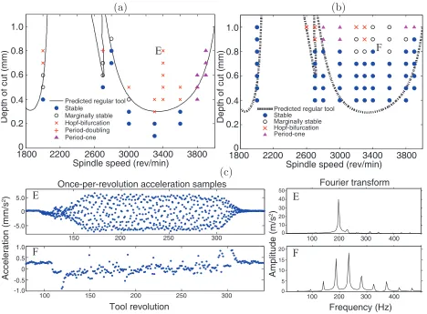
The DE optimisation procedure must be combined with the analytical method for chat-ter stability prediction, in order to optimise the tool geometry so as to avoid chatchat-ter. The resulting procedure is summarised in Fig. 6. Here, four processes can be seen, namely ini-tialisation, semi-discretisation method, objective function evaluation, and DE optimisation. This procedure is as follows:
1. DE parameters are first set to create an initial population for the optimisation process. 2. For each member of the population, predicted stability values are obtained from the SDM algorithm, for the selected range of spindle speeds and depths of cut. The average stability is then calculated.
3. With each new generation of candidate solutions, the DE algorithm produces new
in-put values for the SDM process, i.e. variable helix parameters, βi and variable pitch
Setting up parameters - population size - number of generation - crossover
- mutation rate
Initialise population
Updated population DE algorithm:
- crossover - mutation - selection - generation
Initialise inputs
Semi discretisation method
DE optimisation Initialisation
Objective function evaluation
Perform calculation
Calculate objective function
Return results
Termination criteria
[image:12.595.141.480.226.580.2]met
4. This sequence of operations continues and repeats until a termination criteria is achieved, and the most stable tool geometry is then returned.
Preliminary numerical results [23] have demonstrated that this optimisation approach should enable substantial increases in chatter stability. In the next section, this capability will be investigated experimentally.
4. Experimental testing
4.1. Experimental setup
In this section, an experimental procedure is described that will be used to investigate the performance of optimised variable helix tools compared to traditional uniform pitch uniform helix tools.
The same experimental configuration was used as described in Section 2.2, i.e. a custom-built flexible Aluminium 7075-T6 workpiece. Machining was performed on a Haas VF6 CNC milling machine. The workpiece was to be down-milled at 10 percent radial immersion using a 16 mm diameter 3 flute end mill cutter. For the regular tool, the tangential cutting
force coefficient was estimated to be 1250 MN/m2, and the radial cutting force coefficent
was estimated to be 188 MN/m2. To minimise the static milling force magnitudes and to
prevent large free vibration amplitude because of the interrupted cutting that was applied on the workpiece, a nominal chip thickness of 0.04 mm per tooth was used. A sequence of experiments were performed for a range of spindle speeds and axial depths of cut. At the end of each cutting test, it was necessary to perform a clean-up pass to ensure a sufficiently smooth surface for later tests. Signal acquisition and processing was the same as that described in Section 2.2, except that during each cutting test, the flexure acceleration was measured using a piezoelectric accelerometer (PCB 352C68) rather than a displacement probe.
4.2. Results
The results for regular and optimised tools will be now presented to measure the effec-tiveness of the variable helix approach to mitigating chatter.
The three flute of regular cutter had a uniform helix of (30◦
,30◦
,30◦
) and uniform pitch
of (120◦
,120◦
,120◦
). It should be pointed out that this cutter was substantially stiffer than the flexible workpiece. Consequently the structural dynamics of the cutter can be neglected when optimising its geometry and when predicting the chatter stability.
A corresponding variable helix and variable pitch milling cutter was first designed us-ing the optimisation procedure as described. The optimisation algorithm converged to an average CM value of 0.923 after 47 generations, as shown in Fig. 7. Note that this is an average value of the maximum CMs across a selected range of spindle speeds and depths of cut. Consequently this value does not necessarily indicate complete stability of the system, despite the value being less than unity. In fact the optimised cutter was completely stable over the selected range of spindles speeds and depths of cut. This cutter consisted of a
variable helix geometry (43◦
,44◦
,48◦
) and variable pitch geometry (84◦
,221◦
,55◦
Figure 7: Optimisation results - evaluated objective function for increasing number of generations. (a) (b) (c) E F E F E F 0
1800 2200 2600 3000
Spindle speed (rev/min)
Predicted regular tool Stable
Marginally stable Hopf-bifurcation Period-one Predicted regular tool
Stable Marginally stable Hopf-bifurcation Period-doubling Period-one 3400 3800 0.2 0.4 0.6 0.8 1.0 0 0.2 0.4 0.6 0.8 1.0 5.0 -5.0 0
150 200 250 300
100 150 200 250 300
0.5 0 -0.5 -1.0 1.0 40 30 20 10 0 50 20 15 10 5 0
1800 2200 2600 3000
Spindle speed (rev/min)
Once-per-revolution acceleration samples
Tool revolution
100 200 300 400 100 200 300 400
Frequency (Hz) Fourier transform D e p th o f cu t (mm) Acce le ra ti o n (mm/ s 2) Amp lit u d e (m/ s 2) D e p th o f cu t (mm) 3400 3800
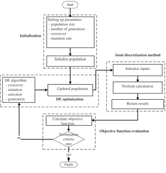
[image:14.595.65.533.329.674.2]The chatter stability of the original (regular helix, regular pitch) cutter and the opti-mised cutter is shown in Fig. 8. It can be seen that the regular cutter (Fig. 8a) is relatively unstable in the selected range of spindle speeds and depths of cut. There is good agree-ment between the predicted and experiagree-mental behaviour. However, at high spindle speed, resonance occurred due to similarities of the chatter and spindle frequencies. Note that the so-called ’flip lobe’ that is associated with period doubling behaviour occurs at 2700 rev/min. This lies on to the left of the main stability lobe due to the use of down-milling rather than up-milling, as illustrated by [24]. It can be seen that the critical depth of cut for the original cutter was experimentally confirmed to be less than 0.3 mm. Meanwhile, the optimised tool (Fig. 8b) is predicted to be completely stable across this range of cutting conditions, so that the stability boundary cannot be seen on Fig. 8b. In fact, the critical depth of cut is predicted to increase 8 fold when compared with the regular cutter. For comparison purposes, the stability boundary for the regular tool is shown superimposed on
Fig. 8b, and a large number of stable cuts can be observed under conditions where the
reg-ular tool was predicted to become unstable. However, some unexpected unstable behaviour
occurred at the higest depths of cut. Further work is needed to investigate whether this can be attributed to tool runout effects in conjunction with the use of a very flexible workpiece. A closer comparison between the two tools is shown in Fig. 8c. Here, test cut ‘E’ (regular tool, 0.8mm, 3600 rev/min) is compared to test cut ‘F’ (variable helix tool, same conditions). The once-per-revolution acceleration signals are plotted since a high variance in this data is a well-known indicator of regenerative chatter [24]. It can be seen that test cut ‘E’ exhibits a much higher variance in once-per-revolution samples than test cut ‘F’. Meanwhile, the Fourier analysis in Fig. 8c shows that the vibration in test cut ‘E’ is completely dominated by vibration at the regenerative chatter frequency (200 Hz) unlike the vibration in test cut ‘F’. Consequently, the increased stability of the variable helix tool is clearly illustrated.
5. Discussion
A number of issues are worthy of further discussion. First, it should be pointed out that in the present study, the structural dynamics of the system have been relatively simple, with a single constant mode of vibration of the flexible workpiece. In practice milling chatter is often associated with the structural dynamics of the tool. This raises an additional complication for the optimisation process, because the tool dynamics are likely to be sensitive to the tool helix angle. Two possible ways to overcome this issue are (a) the inclusion of an FE prediction of the tool dynamics within the optimisation algorithm, or (b) modifying the algorithm so as to also optimise the robustness to variations in the structural dynamics (that are assumed constant). Nevertheless, the Differential Evolution approach would be applicable to either of these methods.
very extreme variable pitch angle, and a less extreme variable pitch angle. Consequently, at the low axial depths of cut that were considered, the overall behaviour of this tool could have been matched by that of a variable pitch tool, with no need for a variable helix. However, in other scenarios considered by the authors, the DE algorithm has shown that allowing a variable helix as well as a variable pitch can offer superior chatter stability. Clearly, the additional design variables that are provided by a variable helix tool can pave the way for potentially greater performance compared to variable pitch tools. However, this is at the cost of greater complexity and potentially greater sensitivity to other model parameters, such as the structural dynamics and the cutting force coefficients. Further work would be useful to explore these trade-offs in more detail.
Third, there are a number of ways in which the optimisation problem can be formulated, in addition to the choice of which algorithm to use. The present work focussed on a Differen-tial Evolution strategy. The algorithm was benchmarked against a more traditional approach (Sequential Quadratic Programming, or SQP) during the development stages [23], and the DE strategy was found to consistently out-perform the SQP algorithm. However, there are a number aspects of the optimisation algorithm that could be explored in more detail. For example, a multi-objective optimisation procedure would help to illustrate the compromise between metal removal rate and degree of chatter stability. Meanwhile, the fact that DE out-performed SQP indicates that the optimisation problem is nonlinear with locally opti-mal solutions that can cause problems for non-global optimisation strategies. Consequently more work could be done to improve the efficiency of the optimisation algorithm and to compare the performance with alternative approaches.
It should also be pointed out that the present study has focussed on machining of Alu-minium 7075-T6 alloy, and that the machining stability of harder materials such as steel has not been considered. In the case of harder workpieces, other factors are likely to influence the choice of processing conditions (spindle speed, depth of cut, etc). For example, tool wear could be far more significant, and thermal conductivity issues (e.g. in titanium alloys) could limit the surface speed. In contrast, the productivity of machining aluminium alloys can be enhanced considerably by properly understanding regenerative chatter issues [25], and this has motivated many recent studies that have also focussed purely on aluminium alloys (e.g. [24, 26, 27, 28]). The present study provides a new tool for this approach which allows the regions of chatter stability to be tailored, by adjustment of the tool helix geometry, to suit a particular application. Nevertheless, the application of the approach to other workpiece materials remains a topic for future research.
6. Conclusions
This contribution has developed an optimisation procedure so that regenerative chatter can be avoided by using variable helix milling tools with a custom geometry. A recently pro-posed stability model for variable helix milling tools [15] has been experimentally validated, and a Differential Evolution algorithm was developed that incorporated the chatter stability model. This allowed the tool helix and pitch angles to be optimised so as to minimise chatter for a given set of conditions. The specific conclusions are as follows:
1. Variable helix tools can be designed to provide substantial performance improvements compared to traditional tools, due to their improved chatter stability. In the present study, a five-fold improvement in chatter stability (compared to a regular tool) was experimentally observed.
2. Variable helix tools suffer from period-one chatter instability, which (to the authors’ knowledge) has been experimentally observed for the first time in this work. This type of instability is difficult to identify because the vibration frequency coincides with the force vibration frequency from tool rotation. Furthermore, the instability can occur in small isolated regions of the stability diagram, so that small changes in the process parameters can have a large effect on the stability.
3. Variable helix tools give greater flexibility over the process variables that influence chat-ter. In particular, they introduce additional design variables (helix angles and pitch angles) that can be used to optimise process parameters. This optimisation process is non-trivial due to the nonlinear relationship between the design variables and the objective (to reduce chatter). In the present study, this was overcome using a Differ-ential Evolution algorithm, which was shown to produce viable tool geometries with substantial improvements in chatter stability compared to regular tools.
Finally, further work is needed to include the effects of tool runout in the modelling and optimisation process. It is also important to consider the more complex scenario where the tool’s structural dynamics are included in the optimisation algorithm.
Acknowledgement
Appendix
Ad=
"
0 · · · 0 [N−1] 0 [I][(N−1)×(N−1)]
0 · · · 0 T[N−1]
#
[0]
[0]
"
0 · · · 0 [N−1] 0 [I][(N−1)×(N−1)]
0 · · · 0 T[N−1]
#
Bd=
n
1
0 · · · 0 T[N−1]
o
0 · · · 0 T[N−1]
0 · · · 0 T[N] n 1
0 · · · 0 T[N−1] o
Cd =
−[I][N×N] [0]
[0] −[I][N×N]
Dd =
"
1 · · · 1 T[N]
0 · · · 0 T[N]
0 · · · 0 T[N]
1 · · · 1 T[N]
#
(9)
References
[1] J. L. Dohner, J. P. Lauffer, T. D. Hinnerichs, N. Shankar, M. Regelbrugge, C.-M. Kwan, R. Xu, B. Winterbauer, K. Bridger, Mitigation of chatter instabilities in milling by active structural control, Journal of Sound and Vibration 269 (2004) 197.
[2] Y. Zhang, N. D. Sims, Milling workpiece chatter avoidance usingpiezoelectric active damping: a feasibility study, Smart materials and structures 14 (2005) 65–70.
[3] N. D. Sims, Vibration absorbers for chatter suppression: A new analytical tuning methodology, Journal of Sound and Vibration 301 (2007) 592–607.
[4] Y. Yang, J. Muoa, Y. Altintas, Optimization of multiple tuned mass dampers to suppress machine tool chatter, International Journal of Machine Tools and Manufacture In Press, Corrected Proof (????). [5] Y. S. Liao, Y. C. Young, A new on-line spindle speed regulation strategy for chatter control,
Interna-tional Journal of Machine Tools and Manufacture 36 (1996) 651.
[6] E. Soliman, F. Ismail, Chatter suppression by adaptive speed modulation, International Journal of Machine Tools and Manufacture 37 (1997) 355.
[7] S. Jayaram, S. G. Kapoor, R. E. DeVor, Analytical stability analysis of variable spindle speed machin-ing, Journal of Manufacturing Science and Engineering 122 (2000) 391–397.
[8] Y. Altintas, S. Engin, E. Budak, Analytical stability prediction and design of variable pitch cutters, Journal of Manufacturing Science and Engineering, Transactions of the ASME 121 (1999) 173. [9] E. Budak, An analytical design method for milling cutters with non-constant pitch to increase stability,
part 1: Theory and part 2: Application, Journal of Manufacturing Science and Engineering 125 (2003) 29–38.
[10] N. Olgac, R. Sipahi, Dynamic and stability of variable pitch milling, Journal of Vibration and Control 13 (2007) 1031–1043.
[11] H. Opitz, E. U. Dregger, H. Rose, Improvement of the dynamics stability of the milling process by irregular tooth pitch, Advances in Machine Tool Design and Research, Proc. of MTDR Conference 7 (1966) 213–227.
[13] B. J. Stone, The effect on the chatter behaviour of cutters with different helix angles on adjacent teeth, Advances in Machine Tool Design and Research, Proc. of 11th International MTDR Conference University of Birmingham A (1970) 169–180.
[14] S. Turner, D. Merdol, Y. Altintas, K. Ridgway, Modelling of the stability of variable helix end mills, International Journal of Machine Tools and Manufacture 47 (2007) 1410.
[15] N. D. Sims, B. Mann, S. Huyanan, Analytical prediction of chatter stability for variable pitch and variable helix milling tools, Journal of Sound and Vibration 317 (2008) 664–686.
[16] T. Insperger, G. Stepan, Semi discretization method for delayed system, International Journal for Numerical Methods in Engineering 55 (2002) 503–518.
[17] J. M. T. Thompson, H. B. Stewart, John Wiley & Sons, West Sussex, 2002.
[18] T. Insperger, B. P. Mann, T. Surmann, G. Stepan, On the chatter frequencies of milling processes with runout, International Journal of Machine Tools and Manufacture 48 (2008) 1081–1089.
[19] K. Price, R. Storn, J. Lampinen, Differential Evolution: A Practical Approach to Global Optimization, Springer, Berlin Heidelberg, 2005.
[20] S. Saikumar, M. Shunmugan, Parameter selection based on surface finish in high speed finish in high speed end milling using differential evolution, Materials and Manufacturing Processes 21 (2008) 341– 347.
[21] A. Krishna, Selection of optimal conditions in the surface grinding process using a differential evolution approach, Proceedings of the Institution of Mechanical Engineers, Part B: Journal of Engineering Manufacture 221 (2007) 1185–1192.
[22] B. Markus, Differential evolution, 2008.
[23] A. Yusoff, N. D. Sims, Optimisation of variable helix end milling tools by minimising self-excited vibration, Journal of Physics: Conference Series on 7th International Conference on Modern Practice in Stress and Vibration Analysis 181 (2009) 012026.
[24] B. Patel, B. Mann, K. Young, Uncharted islands of chatter instability in milling, International Journal of Machine Tools and Manufacture 48 (2008) 124–134.
[25] J. Tlusty, Manufacturing Processes and Equipment, Prentice Hall, New Jersey, 1999.
[26] U. Bravo, O. Altuzarra, L. Lpez de Lacalle, J. Snchez, F. Campa, Stability limits of milling consid-ering the flexibility of the workpiece and the machine, International Journal of Machine Tools and Manufacture 45 (2005) 1669–1680.
[27] F. Campa, L. Lpez de Lacalle, A. Celaya, Chatter avoidance in the milling of thin floors with bull-nose end mills: Model and stability diagrams, International Journal of Machine Tools and Manufacture In Press, Accepted Manuscript (????) –.