This is a repository copy of
On Power Sharing and Stability in Autonomous Inverter-Based
Microgrids
.
White Rose Research Online URL for this paper:
http://eprints.whiterose.ac.uk/92379/
Version: Accepted Version
Proceedings Paper:
Schiffer, JF orcid.org/0000-0001-5639-4326, Anta, A, Trung, TD et al. (2 more authors)
(2012) On Power Sharing and Stability in Autonomous Inverter-Based Microgrids. In: 2012
IEEE 51st IEEE Conference on Decision and Control (CDC). 2012 IEEE 51st IEEE
Conference on Decision and Control (CDC), 10-13 Dec 2012 IEEE , pp. 1105-1110. ISBN
9781467320658
https://doi.org/10.1109/CDC.2012.6426704
[email protected] https://eprints.whiterose.ac.uk/ Reuse
Unless indicated otherwise, fulltext items are protected by copyright with all rights reserved. The copyright exception in section 29 of the Copyright, Designs and Patents Act 1988 allows the making of a single copy solely for the purpose of non-commercial research or private study within the limits of fair dealing. The publisher or other rights-holder may allow further reproduction and re-use of this version - refer to the White Rose Research Online record for this item. Where records identify the publisher as the copyright holder, users can verify any specific terms of use on the publisher’s website.
Takedown
If you consider content in White Rose Research Online to be in breach of UK law, please notify us by
On power sharing and stability in autonomous inverter-based
microgrids
Johannes Schiffer, Adolfo Anta, Truong Duc Trung, J¨org Raisch, Tevfik Sezi
Abstract— We consider the problem of voltage and frequency stability for an autonomous inverter-based microgrid. An LMI-based decentralized feedback control design is derived that stabilizes the system under the consideration of droop-like controllers aiming to achieve power sharing among the dif-ferent generation units. We provide a design procedure that accounts for uncertainties in line impedances and loads while guaranteeing zero steady-state frequency deviation.
I. INTRODUCTION
An increasing amount of renewable energy sources is present in the electrical grid, of which a large share are small-scale distributed generation units connected at the low (LV) and medium voltage (MV) levels via inverters. The physical characteristics of such power electronic de-vices largely differ from the characteristics of conventional electrical generators (e.g. synchronous generators (SGs)), and therefore different control strategies are needed [1]. Moreover, since these generation units are intermittent by nature, more flexible operation and control strategies are needed to balance consumption and generation. Microgrids represent one promising solution that has received increasing attention in recent years [2]. It addresses these issues by gathering a combination of generation units, loads and energy storage elements at distribution level into a locally control-lable system, which can be operated in a decentralized and even completely isolated manner from the main transmission system. Microgrids have been identified as a key component in future electrical networks [3]. Many new problems arise for this type of networks. In this paper we focus on the problem of guaranteeing voltage and frequency stability for a microgrid under droop-like control (see below) by providing additional decentralized feedback. The problem of power sharing mainly addresses the following question: upon load changes in the system, how should the different generation units in the network adjust their output power in order to fulfill the demand while satisfying a desired power distribution. It is a requirement to achieve these objectives in a decentralized way without communication among units and allowing for a plug-and-play-like operation [2].
A control solution widely used to tackle this problem in large power systems is droop control [4]. Under this
This work was supported by Siemens AG, the Alexander von Humboldt Foundation and the Ministry of Education of Vietnam.
J. Schiffer and T.D. Truong are with the Technische Universit¨at Berlin, Germany{schiffer,truong}@control.tu-berlin.de
A. Anta and J. Raisch are with the Technische Universit¨at Berlin & Max-Planck-Institut f¨ur Dynamik komplexer technischer Systeme, Germany
{anta,raisch}@control.tu-berlin.de
T. Sezi is with Siemens AG, Smart Grid Division, Nuremberg, Germany [email protected]
approach, the current value of the frequency in the network is monitored to derive how much active power each generating unit needs to provide. In this way, the frequency (present everywhere in the network) serves as an implicit communi-cation signal. From a control perspective, droop control can be regarded as a proportional controller where the control gain (known as droop gain) specifies the steady-state power distribution in the network. Since performance under droop control is satisfactory for transmission systems, researchers have first tried to apply this technique to microgrids [5], [6], [7], [8]. Stability analysis is usually carried out by means of detailed small-signal analysis as well as extensive simulations and experimental studies aiming to characterize a range for the droop gains guaranteeing system stability. In this regard, several articles [9], [10] propose to make inverters resemble the input/output behavior of SGs, so that the widely existing knowledge and expertise on SGs can be directly applied to inverter-based networks.
However, microgrids exhibit some characteristics that con-siderably differ from large power systems and therefore complicate a direct implementation of droop-like control methods. Examples of such characteristics are low inertia, no inherent physical relation between network frequency and power balance, possibly large R/X ratio, etc. [11], [12]. Several modifications to droop control have been pro-posed [13], [14], where the stability problem is either ignored or simplified by dealing with a linear model. While droop control provides a satisfactory performance in terms of power sharing, it has been observed that droop control can result in poorly damped or even unstable systems [6], [8], [15], [16]. Recently, conditions for proportional power sharing and synchronization of a microgrid under frequency droop control have been derived in [17] by applying results of the theory of coupled oscillators. The considered model rep-resents a lossless strongly-connected autonomous inverter-based network with constant bus voltages.
To the best of the authors’ knowledge, there is no pub-lished work so far that provides a control design for inverter-based networks guaranteeing overall network stability for the nonlinear model considering variable voltages and arbitrary
R/X ratios of the lines while accounting for power sharing. Our main contributions in this sense are twofold. First, we provide a decentralized control design for robust stability of the nonlinear model of an inverter-based network formed by an arbitrary number of inverters. Second, the design allows to specify a range for the droop gains, rather than a fixed value. In this way, the power sharing characteristics could then be adjusted e.g., by market mechanisms similar to the
present implementation in many large power systems [18], [19], while preserving stability. Opposed to standard droop control our approach does guarantee zero steady-state fre-quency deviation. The proposed design merges ideas from decentralized control for large power systems of SGs [20], [21], [22] (where stabilizing control laws have been derived for nonlinear models of power systems) and droop control ideas (that target the requirement of power sharing). At the technical level, this is achieved by solving a decentralized output feedback problem for a desired range of the power sharing gains (to be defined by the user). Additionally, we account for line and load uncertainties by considering multiplicative uncertainties in the admittance elements. The control synthesis is also decentralized and formulated as a linear matrix inequality (LMI) optimization problem, which allows for efficient off-line computation. Moreover, this ro-bust decentralized synthesis enables easy plug-and-play-like integration of new generation units in the network without recomputing controller gains of existing units, if the latter have been determined accounting for sufficient robustness with respect to uncertainties in loads and line impedances.
II. MODELING OF A MICROGRID
Whenever a grid is mainly formed by inverters, the latter are normally operated in voltage source mode. A voltage source inverter (VSI) behaves as a voltage source with con-trollable magnitude and frequency of the output voltage [23]. To address the stability problem, the inverter is modeled as an ideal voltage source where all internal control loops but the power control loop are neglected [6], [8]. Given a particular network, we work with the Kron-reduced admittance matrix of the network, a standard method in power systems to eliminate passive nodes [4]. Based on these assumptions, the active and reactive power flow exchange at node i is given by:
Pi =
n
X
j=1
αij|Yij|ViVjcos(δi−δj−φij)
Qi =
n
X
j=1
αij|Yij|ViVjsin(δi−δj−φij), (II.1)
whereδiandδj are the phase angles at nodeiandj,δ˙i and
˙
δjtheir corresponding frequencies,ViandVjare the voltage magnitudes, |Yij| represents the expected magnitude of the admittanceYij between node iandj,φij is the admittance angle ofYij,(αij−1)represents a multiplicative uncertainty in |Yij| andn is the number of nodes in the network. All phase angles δi are expressed with respect to an arbitrary rotating reference frame with angular velocity ωnom[7].
The active and reactive power flows are measured through a low pass filter with time constantτPi:
˙˜ Pi=
1 τPi
−P˜i+Pi
, Q˙˜i =
1 τPi
−Q˜i+Qi
,(II.2)
where P˜i and Q˜i denote the measured active and reactive power. In most power control approaches, e.g., droop control, the inverter output frequency δ˙i is controlled instead of directly controlling the phase angle δi [7]. Further, we
consider the input delay in the voltage via another low-pass filter with time constantτVi ≪τPi, hence
˙
δi=uai, V˙i=
1 τVi
(−Vi+Vid+u b
i), (II.3) whereVd
i denotes the desired (nominal) operating voltage. In that way, the model resembles the typical droop control structure.
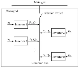
Based on (II.1), (II.2) and (II.3), we now build a nonlinear multi-inverter network (Fig. 1). Notice that in the here considered case of an autonomously operated network the isolation switch is open. We denote by
ye
i = [δei VieP˜ieQ˜ei]T, i= 1, . . . , n an equilibrium point of the network, characterized by equations (II.1), (II.2) together with (II.3) andua,ei = 0, ub,ei =const. This equilibrium point
ye
i is usually not completely known explicitly in power systems, as it depends on the network topologies and load conditions (that are represented in the model through the uncertainty coefficientsαij). In order to derive control laws guaranteeing stability with respect toye
i, we define our state variables as:
xi1 =δi−δ
e
i, xi2 =Vi−V
e
i, (II.4)
xi3 = ˜Pi−P˜
e
i, xi4= ˜Qi−Q˜
e
i, i= 1, . . . n.
Further we define:
∆ui=
∆ua
i
∆ub
i
=
ua
i−u a,e i
ub i−u
b,e i
, i= 1, . . . , n. (II.5)
Hence, we can rewrite the dynamics for the deviations from the equilibrium point at node ias follows:
˙
xi(t) =Aixi(t) +Bi∆ui(t) + n
X
j=1
κijGifij(xi, xj) (II.6)
withBi=Bi1 0
T , Gi=
h
0 1
τPiI
iT
,
Ai =
A
i1 0
0 − 1
τPiI
, Ai1=
0 0
0 − 1
τVi
, Bi1 =
1 0
0 1
τVi
.
andκij are constants with values either 1 or 0 (κij = 0 means that the jth subsystem is not connected with theith subsystem). The nonlinear interconnections are given by:
fij(xi, xj)=
αij|Yij|
(xi2+V
e
i)(xj2+V
e j)
cos(xi1−xj1+ ˜φij)−V
e
iVjecos( ˜φij)
αij|Yij|
(xi2+V
e
i)(xj2+V
e j)
sin(xi1−xj1+ ˜φij)−V
e
iVjesin( ˜φij)
,
whereφ˜ij=δei−δje−φij.
III. ADECENTRALIZED CONTROL SOLUTION FOR VOLTAGE AND FREQUENCY STABILITY
In this paper we propose a decentralized control design procedure that achieves stability (with respect to ye
i) of system (II.6) for a given set of droop-like controllers aiming to achieve power sharing among the different nodes in the network. From a control perspective, the power sharing requirement relates to the design of the control law so that the equilibrium point ye
Inverter 1
Inverter 2
Inverter 3
Invertern P1,Q1
P2,Q2
P3,Q3
Pn,Qn u1
u2
u3
un Main grid
Isolation switch
Common bus Microgrid
[image:4.612.108.245.53.172.2]. ..
Fig. 1. Schematic representation of a multi-inverter network.
regardless of the network conditions (i.e., regardless of the current value of αij.) Indeed, looking at the state equations in (II.1), (II.2) and (II.3) it can be concluded that the equilibrium point ye
i is just partially determined by the control laws. In particular, the difference between the current equilibrium point ye
i and a so-called nominal equilibrium pointyd
i = [δdi VidP˜idQ˜di]T, i= 1, . . . , n(that typically cor-responds to the nominal operating conditions) is of interest. For that matter, we define the deviations of the system variables with respect to their desired values as
zi1=δi−δ
d
i, zi2 =Vi−V
d
i, (III.1)
zi3= ˜Pi−P˜
d
i, zi4 = ˜Qi−Q˜
d
i, i= 1, . . . n.
We would like to point out that the choice of the nominal operation point does not affect the stability of the system and can thus be made arbitrarily, but will affect the steady state
ye
i as will be shown in the following. We further divide the control input ui= [uai ubi]T in two components:
ui(t) =ui1(t) +ui2(t) =−Ki1zi(t)−Ki2zi(t). (III.2)
Notice that the control law depends on zi and not on xi, since ye
i is unknown and thereforexi is not available. The first input ui1 imitates the effect of droop control and is
thus responsible for power sharing, whereasui2 stabilizes the
system onceKi1 has been selected. We include this second
componentui2 since, to the best of our knowledge, it has not
been proven that droop control can stabilize an inverter-based network (considering a nonlinear model). The role played by
ui1 is to modify the voltage magnitude and angle according
to the active and reactive power in the spirit of droop control:
ui1(t) =−Ki1zi(t), Ki1 =
0 KP Qi
. (III.3) Different structures can be considered for the matrixKP Qi.
While our formal approach is valid for any structure of
KP Qi, we focus for simplicity on the following diagonal
matrix:
KP Qi =
kPi 0
0 kQi
, (III.4)
with kPi > 0 and kQi >0, which is the most commonly
proposed pairing [6]. Under this controller gain, the voltage angle of the inverter is modified according to the active power at the node, while the reactive power modifies the voltage magnitude. Other pairings to achieve power sharing have been proposed in the literature [14], [24], [13]. The gains kPi and kQi are coefficients selected by the user
according to the desired power distribution in the network (as in droop control). Such gains might not be known
beforehand; instead, the user might adjust them according to the status of the network, number of generation units present, economic factors,...[18], [19]. To account for this case, our approach considers a set of droop-like gain matrices
Ki1∈Γi:{[0,diag(kPi, kQi)]|0≤kPi ≤¯kPi,0≤kQi ≤¯kQi}
rather than preassigned specific values. Once Ki1 has been
specified, the second gain matrix Ki2 has to be designed
to guarantee stability. It can be proven1 that a feedback
law of the form ui2 = [−kδizi1 −kVizi2]
T can stabilize the system for sufficiently large kδi and kVi. Under such
control lawsui1 andui2, the following holds in steady state
for system (II.6) inz-coordinates:
ze i1 =−
kPi
kδi
ze i3, z
e i2=−
kQi
kVi+ 1
ze i4,
ze i3 =
n
X
j=1
αijYij(Vid−
kQi
kVi+ 1
ze i4)(V
d j −
kQj
kVj + 1
ze j4)·
cos(δd
i −
kPi
kδi
ze i3−δ
d j+
kPj
kδj
ze j3−φij)
−P˜d i,
ze i4 =
n
X
j=1
αijYij(Vid−
kQi
kVi+ 1
ze i4)(V
d j −
kQj
kVj + 1
ze j4)·
sin(δd
i −
kPi
kδi
ze i3−δ
d j+
kPj
kδj
ze j3−φij)
−Q˜d
i. (III.5) Similar to droop control, the steady-state deviations of
zi1 and zi2 are determined by those of active and reactive
powerzi3, zi4 via the relations kPi/kδi andkQi/(kVi+ 1).
The heuristic approach of droop control is that by choosing adequate relations of the droop gains at nodes i and j
one obtains the desired power sharing between those inverters, which in our case is reflected by the steady-state differences in phase angles δe
i =δid−kPi/kδiz
e i3,
δe
j =δjd−kPj/kδjz
e
j3 and voltage amplitudes
Ve i =V
d
i −kQi/(kVi+ 1)z
e i4, V
e j =V
d
j −kQj/(kVj + 1)z
e j4.
The role of the stabilizing gains kδi, kVi can be interpreted
as a restriction in magnitude of the user-selected droop gains kPi, kQi in order to guarantee stability. That overall
network stability requires constraints on the droop gains has been reported by several authors [6], [8]. To maximize the effect of the user-selected gains kPi, kQi to achieve a
desired power distribution, the control design proposed in Section III-B attempts at minimizing the gains kδi and kVi
for given upper bounds of the droop gains specified inΓi. While our design method does guarantee overall network stability, we can not make any claims regarding the power sharing performance. Given the complex structure of the interconnected network, such claims are difficult to derive in general and are part of our on-going investigations. Analysis for more specific cases have been presented in [13], [17].
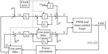
Fig. 2 displays the proposed control structure. Only the output voltage and current need to be measured, from which the active and reactive power can be computed. Notice that the control of active power is done based on the voltage angle
1Not shown here due to space constraints. This fact can be easily
concluded usingV = Pn
i=1Vi = Pni=1xTixi as a control Lyapunov
[image:4.612.317.557.205.345.2]-+ + -- + + + -+ - + PWM and inner control loops Grid Low pass filter Power calculation Clock sync. kP kQ kδ kv ˜ P Pd z3 z4 ˜ Q Qd V Vd z2 δd
z1 δ
ωnom
R R
v(t),i(t)
[image:5.612.68.289.55.167.2]Low pass filter
Fig. 2. Decentralized control structure with clock synchronization signal for referencing.
and not voltage frequency, as in traditional droop control. A similar option has been previously explored in [15]. As mentioned in the introduction, this solution guarantees zero steady-state deviation for the frequency. It is clear that this property, among other benefits, removes the need for secondary control in charge of frequency restoration. The proposed method requires referencing for clock synchroniza-tion, that can be achieved for instance via GPS [15]. We now formally define the problem addressed in this paper:
Problem 3.1: Given a desired droop-like control law
ui1 =−Ki1zi and a set of desired droop-gain matrices
Ki1∈Γi:{[0,diag(kPi,kQi)]|0≤kPi ≤k¯Pi,0≤kQi ≤¯kQi},
design a decentralized control ui2 =−Ki2zi that stabilizes
the system (II.6) (fori= 1, . . . , n).
Remark 3.2: Note that for ease of explanation, we assume the particular structure ofKP Qi given in (III.4) throughout
the paper. Our approach always guarantees stability (for appropiate values ofKi2) independently of the chosen
struc-ture of KP Qi, although the quality of power sharing might
deteriorate if the system characteristics assumed during the design process do not match the real system.
A. Preliminaries
1) Bounds for nonlinearities: Before proposing a design procedure for Ki2, we analyze the nonlinearities present
in the network model in (II.6). Given an operating region
Ω⊂Rn such that 0∈Ω, we can derive a quadratic bound for the nonlinearities in (II.6). In particular, we select a setΩ :{(x1, x2, x3, x4)∈R
4
|x2< Vmax−Ve}, whereVmax
represents the maximum operating voltage of the considered power system. Using the H¨older inequality2ab≤ 1
µa
2
+µb2
together with standard trigonometric identities, we obtain: n
X
j=1
fT ijfij ≤
n
X
j=1,j6=i
2α2
ijY
2
ij
(1 +µ)V2
max(x
2
i2+x
2
j2)
+ (1 + 1
µ)V
4
max(x
2
i1+x
2
j1)
+ 4α2
iiY 2 iiV 2 maxx 2 i2 = n X j=1 xT
iFiTijFiijxi+
n
X
j=1
xT
jFjTijFjijxj (III.6)
for appropiate values ofFiij andFjij. We further define for
convenienceFT
i Fi=Pnj=1 (F
T
iijFiij +F
T ijiFiji).
Remark 3.3: These bounds are valid provided that the state trajectories stay in the set Ω. A fairly simple, though conservative, estimate of Ω for initial conditions satisfying
|x0| ≤r is given by:
Ω :{x∈R4| |x(t)| ≤
s
λmax(Φ)
λmin(Φ)
r, t≥0} (III.7)
where λmax and λmin are respectively the
maximum and minimum eigenvalues of
Φ =blockdiag[Φ1, . . . ,Φn] =blockdiag[W−
1
1 , . . . , W− 1
n ], as defined in the proof of Theorem 3.4. Equation (III.7) allows to identify the values of admissible initial conditions.
B. Stabilizing decentralized LMI control design
The following theorem provides a solution to Problem 3.1.
Theorem 3.4: The nonlinear multi-inverter system (II.6) is stabilizable via decentralized linear feedback control for any
Wi,Mi,Ni,i= 1, . . . , nsatisfying the following conditions
∀Ki1 ∈Γi:
ˆ
Ai WiK¯iT1 Bi Gi WiF
T i
¯
Ki1Wi −
1
ǫI 0 0 0
BT
i 0 −ǫI 0 0
GT
i 0 0 −ρI˜ 0
FiWi 0 0 0 −ρI
<0,
MiCi=CiWi, Wi>0, (III.8) whereAˆi=WiATi +AiWi−BiNiCi−CiTNiTBiT,
Ci =I 0,K¯i1= maxKi1(Γi), andρ˜= (ρ
Pn
j=1κij)− 1
. Moreover, the control law is then given by:
ui=−Kizi =−Ki1zi−Ki2zi=−
NiM−
1
i KP Qi
zi.
Proof: The proof draws inspiration from [20], [21] and [22]. Analyzing (II.5) under control (III.2) and considering (II.4) together with (III.1) gives:
∆ui=
∆ua i ∆ub i
=−Kizi+Kizie=−Kixi.
Thus, stability of system (II.6) under control (III.2), is equivalent to stability of
˙
xi=Aixi−BiKixi+ n
X
j=1
κijGifij(xi, xj)
for any zi. We then define a Lyapunov function of the following form:
V =
n
X
i=1
Vi= n
X
i=1
xTi Φixi. (III.9)
DefiningA˜i=Ai−BiKi2 and making use of
XTY +YTX≤ 1
ǫX
TX+ǫYTY (III.10) for ǫ > 0, the time derivative of Vi along the trajectories of (II.6) with the controller given in (III.2) becomes:
˙
Vi= ˙xTi Φixi+xTiΦix˙i
=xT
i
( ˜Ai−BiK¯i1)
TΦ
i+ Φi( ˜Ai−BiK¯i1)
xi + n X j=1
κijfijTGTi Φixi+xTiΦi n
X
j=1
κijGifij
≤xT i
˜ AT
i Φi+ ΦiA˜i+
1 ǫΦiBiB
T
i Φi+ǫK¯iT1K¯i1
xi + n X j=1
κijfijTGTi Φixi+xTiΦi n
X
j=1
κijGifij.
Recalling V =Pn
i=1Vi, using the fact that
Pn
i=1
Pn
j=1aij =Pni=1
Pn
j=1aji and applying (III.10) withρ >0 together with the bounds in (III.6) we have
˙
V ≤
n
X
i=1
xTi A˜TiΦi+ΦiA˜i+
1 ǫΦiBiB
T
i Φi+ǫK¯iT1K¯i1
xi
+xT
iρ n
X
j=1
κijΦiGiGTiΦixi+
1 ρ
n
X
j=1
fT ijfij
≤ n
X
i=1
xT
i A˜TiΦi+ΦiA˜i+ǫK¯iT1K¯i1+
1 ǫΦiBiB
T i Φi
+ρ
n
X
j=1
κijΦiGiGTiΦi+
1 ρF
T i Fi
xi
.
Defining Wi = Φ−
1
i , Wi > 0 and ρ˜ = (ρPnj=1κij)− 1
, using the Schur complement and pre- and postmultiplying with Wi [22], we can rewrite the condition on V˙ as the following bilinear matrix inequalities (BMI) in Wi andKi2
for i= 1,· · ·, n:
WiA˜Ti + ˜AiWi WiK¯iT1 Bi Gi WiF
T i
¯
Ki1Wi −
1
ǫI 0 0 0
BT
i 0 −ǫI 0 0
GT
i 0 0 −ρI˜ 0
FiWi 0 0 0 −ρI
<0. (III.11)
Notice that, because of the particular structure imposed on the controller, the present problem resembles the case of output feedback control. It is well known that the problem of output feedback stabilization inWi andKi2 is nonconvex
and numerically very difficult to solve. There has been exten-sive research on finding appropriate related convex problem formulations via a change of variables [25]. Among others, one possible variable change leads to the W-Problem [26]. Applying this variable transformation to equations (III.11) leads to the proposed LMI optimization problem stated in Theorem 3.4.
Remark 3.5: Notice that Theorem 3.4 holds for any struc-ture of Ki2. However, as discussed at the beginning of
Section III, we are interested in a diagonal structure forKi2,
for the purpose of power sharing. It was also mentioned that the gains in Ki2 should be minimized as well. This can be
achieved by enforcing Ni and Mi to be diagonal matrices and limiting the feedback gains by adding the following constraints to the set of equations (III.8) [25]:
NT
i Ni< κNiIi, M
−1
i < κMiIi,
which can be expressed as the LMIs
−κNiI N
T i
Ni −I
<0,
Mi I
I κMiI
>0, Mi>0. (III.12)
Remark 3.6: Theorem 3.4 not only provides a decentral-ized controller, but also represents a decentraldecentral-ized design: each node can design its controller without the knowledge of the controllers in the other nodes (provided that all nodes follow the control design proposed in (III.8)). Notice as well that the proposed design allows for plug-and-play-like integration of new generation units in the network without recomputing controller gains of existing units.
Inverter 1 Inverter 2
∼
∼
V2 V1
ZL1(YL1)
Z1(Y1) Z2(Y2)
ZL2(YL2) ZL3(YL3)
˜ Z1(Y˜1)
[image:6.612.328.541.52.108.2]˜ Z2(Y˜2)
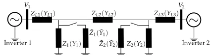
Fig. 3. Test system with two inverters represented as voltage sources.
TABLE I TEST SYSTEM PARAMETERS
Inverter 1 Inverter 2 Voltage magnitude Vd
1 = 232V V2d= 228.5V
and phase angle δd
1= 0rad δ2d=−10−
4
rad Active and P˜d
1 = 15.68kW P˜2d= 15.6kW
reactive power Q˜d
1= 7.73kVar Q˜d2= 5.16kVar
Time constant τP1= 0.0265s τP2= 0.0265s
low pass filter τV1= 10−
3
s τV2= 10−
3
s Control gains kδ1= 17.72
1
s kδ2= 17.72
1 s
via LMI approach kV1= 6.98 kV2= 7.05
User-selected kP1= 10−
2 rad
skW kP2= 10−
2 rad skW
droop gains kQ1= 1
V
kVar kQ2= 1
V kVar
Load impedances Z1= (4 +j1.95) Ω Z2= (2.24+j.79) Ω Zi=Ri+jωLi Z1˜ = (20 +j9.7) Ω Z2˜ = (11.2+j3.7) Ω
Line impedances ZL1= (.01+j.05) Ω ZL2= (.12+j.03) Ω ZLi=Ri+jωLi ZL3= (.01+j.04) Ω
Nominal voltage Vnom= 230V Nominal frequency fnom= 50Hz
IV. AN ACADEMIC EXAMPLE
The presented approach is now implemented on a test system composed of two inverters having each a local load represented by a frequency dependent impedance and being connected via an LV line, Fig. 3. We consider the following scenario in the simulations: the system is first stabilized at the determined equilibrium point; then, att= 1s
(respectively t= 2s) a new load Z˜1 (respectively Z˜2) is connected; subsequently both new loads (Z˜1,Z˜2) are discon-nected simultaneously att= 3s. According to the proposed control design, it is expected that the system stabilizes in all operating conditions and that the new loads are shared among the inverters.
[image:6.612.61.298.289.350.2]The system parameters and control gains are given in Table I. The control parameters for the presented design are derived using the LMIs in (III.8) with kPi ∈[0,10
−2
],
kQi ∈ [0,1] and Vmax = 1.2Vnom. We account for
un-certainties of the absolute values of the elements of Y of up to αij= 1.1,{i, j} ∈ {1,2}, so that the controllers are robust against e.g., load changes. The LMIs are solved using Yalmip 3 [27] together with Sedumi 1.3 under Matlab. The simulations are carried out in Plecs [28].
1 2 3 4 10
15 20
1 2 3 4
2 4 6 8 10
1 2 3 4
49.99 50 50.01
1 2 3 4
−5 0 5
P
[k
W
]
Q
[k
V
a
r]
fIn
v
[H
z
]
θ
[1
0
−
3ra
d
]
t[s]
t[s]
t[s]
[image:7.612.57.302.54.168.2]t[s]
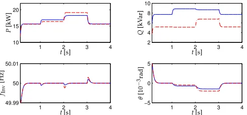
Fig. 4. Test system with proposed control, Inverter 1 ’–’, Inverter 2 ’- -’.
steady-state frequency deviation, a behavior which cannot be achieved with conventional droop control.
In all cases, the active power sharing is improved by over a factor 3/2 with respect to the case without control, although does not represent a share of 50% as suggested by the selected droop gains. A reduction in power sharing performance in favor of stability and zero steady state frequency deviation has also been reported in [15]. Notice as well that there is no overshoot in the active power output, which is favorable for voltage and current limitations in both the DC circuit fed by the renewable source and the inverter. The reactive power sharing is not very accurate. This behavior has been often reported related to droop control in LV networks [29]. The power sharing may be improved by considering inverse droop control or more advanced modified droop control strategies as well as appropiate scaling of the output impedances as proposed e.g., in [14], [29], [24], [13].
V. CONCLUSION
A decentralized feedback control design addressing the problem of voltage and frequency stability for a nonlinear inverter-based microgrid model under droop-like control by providing additional decentralized feedback has been pre-sented. Opposed to standard droop control, our approach guarantees zero steady-state frequency deviation. The control synthesis (also decentralized) is formulated as an LMI and allows for a user-specified range for power sharing gains as well as line and load uncertainties. The presented exam-ple demonstrates the benefits of this approach in terms of zero steady-state frequency deviation and stability. Future research will consider networks that include synchronous generators and inverters as well as formal consideration of the power sharing performance.
VI. ACKNOWLEDGEMENTS
The authors would like to thank Bj¨orn Heinbokel and Ra´ul Mur Artal for helpful discussions on the topics of this paper.
REFERENCES
[1] T.C. Green and M. Prodanovic. Control of inverter-based micro-grids.
Elect. Power Systems Research, Vol. 77(9):1204–1213, july 2007.
[2] R.H. Lasseter. Microgrids. In Power Engineering Society Winter
Meeting, 2002. IEEE, volume 1, pages 305 – 308 vol.1, 2002.
[3] H. Farhangi. The path of the smart grid. IEEE Power and Energy
Magazine, 8(1):18 –28, january-february 2010.
[4] P. Kundur.Power system stability and control. McGraw-Hill, 1994. [5] M.C. Chandorkar, D.M. Divan, and R. Adapa. Control of parallel
connected inverters in standalone ac supply systems. IEEE Trans. on
Industry Applications, 29(1):136 –143, jan/feb 1993.
[6] E.A.A. Coelho, P.C. Cortizo, and P.F.D. Garcia. Small-signal stability for parallel-connected inverters in stand-alone AC supply systems.
IEEE Trans. on Industry Applications, 38(2):533 –542, mar/apr 2002.
[7] N. L. Soultanis, S. A. Papathanasiou, and N. D. Hatziargyriou. A stability algorithm for the dynamic analysis of inverter dominated unbalanced LV microgrids.IEEE Trans. on Power Systems, 22(1):294 –304, feb. 2007.
[8] E. Barklund, N. Pogaku, M. Prodanovic, C. Hernandez-Aramburo, and T.C. Green. Energy management in autonomous microgrid using stability-constrained droop control of inverters.IEEE Trans. on Power
Electronics, 23(5):2346 –2352, sept. 2008.
[9] H.-P. Beck and R. Hesse. Virtual synchronous machine. In9th Int.
Conf. on Electr. Power Quality and Utilisation., pages 1 –6, oct. 2007.
[10] Q. Zhong and G. Weiss. Synchronverters: Inverters that mimic synchronous generators. IEEE Trans. on Industrial Electronics, 58(4):1259 –1267, april 2011.
[11] A. Engler. Applicability of droops in low voltage grids.DER Journal, (1), jan. 2005.
[12] R.M.S. Filho, P.F. Seixas, P.C. Cortizo, and G. Gateau. Small-signal stability enhancement of communicationless parallel connected inverters. InIndustrial Electronics, 2009. IECON ’09. 35th Annual
Conference of IEEE, pages 863 –870, nov. 2009.
[13] Q. Zhong. Robust droop controller for accurate proportional load sharing among inverters operated in parallel.IEEE Trans. on Industrial
Electronics, PP(99):1, 2011.
[14] J.M. Guerrero, J. Matas, Luis Garcia de Vicuna, M. Castilla, and J. Miret. Decentralized control for parallel operation of distributed generation inverters using resistive output impedance.IEEE Trans. on
Industrial Electronics, 54(2):994 –1004, april 2007.
[15] R. Majumder, B. Chaudhuri, A. Ghosh, R. Majumder, G. Ledwich, and F. Zare. Improvement of stability and load sharing in an autonomous microgrid using supplementary droop control loop. IEEE Trans. on
Power Systems, 25(2):796 –808, may 2010.
[16] H.J. Avelar, W.A. Parreira, J.B. Vieira, L.C.G. de Freitas, and E.A.A. Coelho. A state equation model of a single-phase grid-connected inverter using a droop control scheme with extra phase shift control action. IEEE Trans. on Ind. Electr., 59(3):1527 –1537, march 2012. [17] J. W. Simpson-Porco, F. Dorfler, and F. Bullo. Droop-controlled
inverters are Kuramoto oscillators. InIFAC Workshop on Distributed
Estimation and Control in Networked Systems, Santa Barbara, CA,
USA, September 2012. To appear.
[18] C.A. Hernandez-Aramburo, T.C. Green, and N. Mugniot. Fuel consumption minimization of a microgrid. IEEE Trans. on Industry
Applications, 41(3):673 – 681, may-june 2005.
[19] G. Diaz, C. Gonzalez-Moran, J. Gomez-Aleixandre, and A. Diez. Scheduling of droop coefficients for frequency and voltage regulation in isolated microgrids. IEEE Trans. on Power Systems, 25(1):489 – 496, feb. 2010.
[20] Haibo Jiang, Hongzhi Cai, J.F. Dorsey, and Zhihua Qu. Toward a globally robust decentralized control for large-scale power systems.
IEEE Trans. on Contr. Systems Technology, 5(3):309 –319, may 1997.
[21] Y. Wang, D. J. Hill, and G. Guo. Robust decentralized control for multimachine power systems.IEEE Trans. on Circuits and Systems I:
Fundamental Theory and Applications, 45(3):271 –279, mar 1998.
[22] A.I. Zecevic, G. Neskovic, and D.D. Siljak. Robust decentralized exciter control with linear feedback. IEEE Trans. on Power Systems, 19(2):1096 – 1103, may 2004.
[23] J.A.P. Lopes, C.L. Moreira, and A.G. Madureira. Defining control strategies for microgrids islanded operation. IEEE Trans. on Power
Systems, 21(2):916 – 924, may 2006.
[24] Wei Yao, Min Chen, J. Matas, J.M. Guerrero, and Zhao-Ming Qian. Design and analysis of the droop control method for parallel inverters considering the impact of the complex impedance on the power sharing. IEEE Trans. on Ind. Electronics, 58(2):576 –588, feb. 2011. [25] A.I. Zecevic and D.D. Siljak. Design of robust static output feed-back for large-scale systems. IEEE Trans. on Automatic Control, 49(11):2040 – 2044, nov. 2004.
[26] C.A.R. Crusius and A. Trofino. Sufficient LMI conditions for output feedback control problems. IEEE Trans. on Automatic Control, 44(5):1053 –1057, may 1999.
[27] J. L¨ofberg. YALMIP : a toolbox for modeling and optimization in MATLAB. In IEEE International Symposium on Computer Aided
Control Systems Design, pages 284 –289, sept. 2004.
[28] Plecs software. Plexim GmbH, www.plexim.com.
[29] Yun Wei Li and Ching-Nan Kao. An accurate power control strategy for power-electronics-interfaced distributed generation units operating in a low-voltage multibus microgrid.IEEE Trans. on Power Electron-ics, 24(12):2977 –2988, dec. 2009.