International Journal of Innovative Technology and Exploring Engineering (IJITEE) ISSN: 2278-3075, Volume-8 Issue-9S3, July 2019
Abstract: A detailed modelling of soft-switching isolated current-fed dual active bridge (CFDAB) DC/DC converter is presented. This converter is suitable for an interface between two DC buses in a microgrid but is not controlled. The model of the converter is derived with the help of state space averaging method. Based on this modelling, the PI controller designed to improve the operation of the CFDAB converter. Simulation results using MATLAB/Simulink with controller design to verify the stability of the converter and validated performance of the system used for DC microgrid applications of between two buses. The effectiveness of the controller has justified in terms of line, load variation and tracking the reference values.
Index Terms: Bidirectional, Current-fed, DC Microgrid, Dual Active Bridge, PI control
I. INTRODUCTION
Increasing the penetration of sustainable energy sources and storage systems, clustered distributed generations (DGs) have become an interesting option for microgrid. This growth motivates environmental concerns created by the harmful effects of carbon dioxide discharges from the conventional power plants [1], [2]. Resurgence of DC microgrids [3], [4], owing to the development of modern semiconductor technologies and sustainable DC power sources such as photovoltaic (PV), fuel cell and energy storage to enhance the efficiency of power systems, which becomes one of the most prominent research issues in electric energy system. Also, DC microgrid has more advantages [3]-[5] such as, higher efficiency and reduced losses due to the reduction of multiple converters used for dc loads such as electric vehicles and LED lights, there is no need to synchronize the energy generation sources, DC power uses over 90% of household loads [6], [7]. The DC power can maximize the DC DGs preventing the power conversion losses. The terminal of microgrid depends only on power electronic devices, so the converters are the most important part of the microgrid systems. Especially in DC microgrid system, DC/DC converters [8] play the most prominent group of converters. Because, it allows voltage control, power flow control and system balancing. In addition, the bidirectional converter regulates the DC- bus voltage with the help of controllers [9], [10].
Revised Manuscript Received on July 22, 2019.
A. Geetha, Research Scholar, Department of EEE, Pondicherry Engineering College, Pondicherry.
[image:1.595.318.542.167.314.2]N. P. Subramaniam, Assistant Professor, Department of EEE, Pondicherry Engineering College, Pondicherry
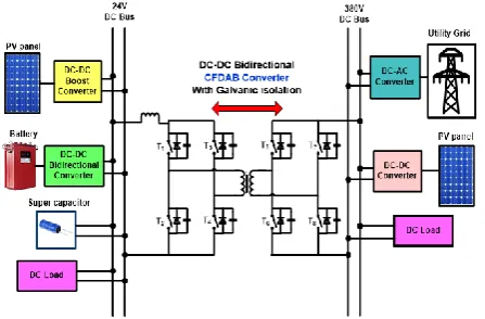
Figure 1: Structure of DC Microgrid Using CFDAB Converter
In Fig. 1 shows the detailed construction of DC microgrid has led to a modern approach of microgrid which comprises an interfacing bidirectional converter (IBC) links the two DC buses. DC microgrid has proposed various bidirectional isolated DC/DC converters [11] to interfaces for energy storage devices. This system uses two buses which have PV generations, storage systems and utility grid etc. Low voltage DC (LVDC) bus connects the outputs of PV array, battery and super capacitors and consumes loads from it. Utility grid uses AC voltage from the high voltage DC (HVDC) bus by converting high DC into AC voltage and PV array aids to provide energy to HVDC bus. To realize power distribution between two buses in DC microgrids, various bidirectional converters [12] proposes to interface between a high and low voltage buses. Photovoltaic array is equipped as the distribution generation and a storage system of a battery or a super capacitor is implements galvanic isolation for IBC. It is needed for flexibility of system reconfiguration and find safety standards an isolated DC/DC converter. Especially, current-fed dual active bridge (CFDAB) topology [13] having input inductor has many advantages compared to traditional converters. They are electrical isolation, high reliability, simple to achieve soft switching control even in case of small load conditions, lowers the turns ratio, small diode ringing and bidirectional power flow. Most of the converters in the DC microgrid act as constant power loads when their outputs are controlled with slight changes around the reference values. For that, use of PI controller [14], [15] to improve the operation of the CFDAB converter. State-space averaging method uses to model the controller.
PI Control of Current-Fed Dual Active Bridge
Converter for DC Microgrid
The objective of this paper proposes PI controller and to improve the performance of CFDAB converter. Modelling of the converter have been discussed in section II. Section III presents description of the PI controller designs of the converter. Simulation results using MATLAB is done to verify the performance of converter and to confirm the controller design in section IV. The conclusion is given in the section V.
[image:2.595.58.277.152.542.2]Figure 2: Circuit Diagram of CFDAB Converter
Figure 3: Key Waveforms of CFDAB Converter
II. MODELLINGOFCFDAB
Fig. 2 shows the structure of the DAB DC-DC converter [16]. It consists of a high frequency transformer with discharge inductance Llk and transformation ratio k, two full active bridges, current-fed/boost inductance LB and capacitance Csin the source side, capacitance Coutand load resistance Rload in the output side. Key waveforms of the converter as shown in Fig. 3. The primary side switches are operated with same gating signal of 80% and secondary side with 20% duty cycle. The operation modes of half-cycle have been explained with the help of equivalent circuits [17]. State variables of the converter are 1. Current through the boost inductor is, 2. Discharge inductor current ilk, 3. Output voltage vout, and 4. Input voltage vs.
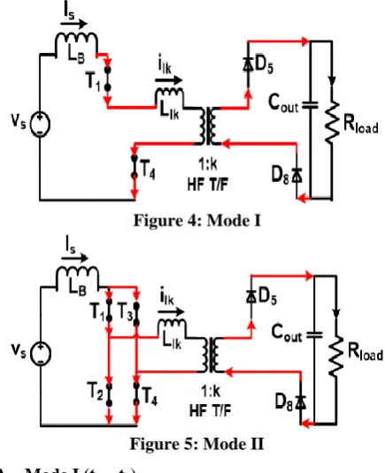
Figure 4: Mode I
Figure 5: Mode II A. Mode I (t2 – t1)
In this mode, switches T1 & T4 of primary bridge and diodes D5 & D8 of secondary bridge are conducting. Current through the leakage inductance is constant and equal to input current is and current in the secondary bridge is Is/n. voltage across the primary of the transformer is vout/k.
B. Mode II (t3 – t2)
[image:2.595.319.485.399.484.2]International Journal of Innovative Technology and Exploring Engineering (IJITEE) ISSN: 2278-3075, Volume-8 Issue-9S3, July 2019
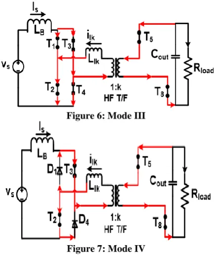
[image:3.595.335.502.168.239.2]Figure 6: Mode III
Figure 7: Mode IV
C. Mode III (t4 – t3)
Secondary switches T5 & T8 are switched on with zero voltage switching (ZVS). Current through discharge inductance further decreases and changes its polarity in negative direction.
D. Mode IV (t5 – t4)
[image:3.595.77.281.569.767.2]In this mode, primary switches T1 & T4 are commutated naturally and current through these switches reduces to zero therefore active devices turn-off with ZCS. Corresponding diodes D1 & D4 are conducting and it causes extended zero voltage appear across T1 & T4 switches. Current through these devices and transformer reach their peak value.
Figure 8: Mode V
E. Mode V (t6 – t5)
During this mode, in secondary side diodes D6 & D7 have ready to take the currents T5 & T8 active devices because currents in the switches T5 & T8 are reduces to zero and going to turn-off. So, the voltage appears across the discharge inductance changes its polarity (positive). At the end of this mode, currents in primary side diodes D1 & D4 decrease to zero and transformer current is equal to the constant input current.
The above-suggested state equations are similar for the next half-cycle because of its symmetry. The averaged state equations over the half-cycle and these values of rate of change of discharge inductance current is zero, i.e.,
Therefore, for analysis simplicity, the state variable ilk is removed and its effects are neglected. Using remaining state variable, the averaged state equations are as follows:
Where, d1= (t2 – t1)/T and d6= (t7 – t6)/T as shown in Fig. 3.
The extended diodes conduction period
d
"
is defined as the half of the total time, i.e.,Where,
fs = switching frequency, T= total time and k=
transformation ratio of isolation transformer. Using
d
"
theequations can be simplified as
" " "
ˆ ˆ ˆ ˆ
i = I + i , v = V + v ,d = D +d,and d = D +ds s s s s s
Therefore, by applying these perturbations and are further simplified by elimination second order terms, dc terms and
"
D , the state equations become,
After taking Laplace Transform of eqn’s. (23) & (24),
In matrix form,
Where,
III. PICONTROLLERDESIGN
[image:4.595.311.471.53.113.2]In Fig. 9 shows the block diagram of PI controller [18], [19] is used to control the CFDAB converter. Open loop converter is the plant to be controlled and the reference input is the set point to control the output voltage. Difference between reference input and feedback signal is called as error signal [20]. The output of the error is given to the PI Controller and then compared with repeating sequence of 100 kHz to generate the duty ratio of the primary active switches.
Figure 9: Block Diagram of PI Co ntrol of CFDAB
PI controller is designed to reduce the steady state error and tries to keep the desired output to the value of the reference input. The transfer function output voltages to duty ratio have derived using the following equations. Using the transfer function of the converter in the equation, gain values have calculated and the values are Kp = 0.0025 and Ki = 0.98.
IV. SIMULATIONRESULTS
The CFDAB converter is simulated using
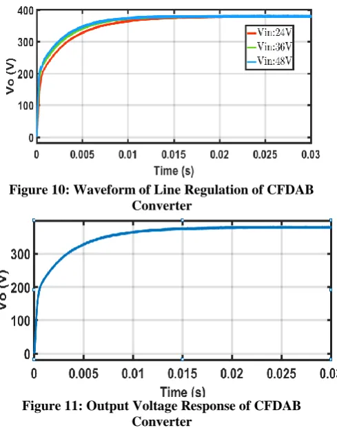
[image:4.595.46.290.124.536.2]MATLAB/Simulink and the following specifications are as follows: vs=24V, vout=380V, Load resistor Rload=144.4Ω, Pout = 1kW, switching frequency fs=100kHz. The boost inductor and series inductor values are LB=36µH and Llk=2µH, values of the input and output capacitors are Cs=Cout=50µF and turns ratio of isolation transformer is k=10.
[image:4.595.309.554.330.642.2]Figure 10: Waveform of Line Regulation of CFDAB Converter
Figure 11: Output Voltage Response of CFDAB Converter
[image:4.595.54.291.657.785.2]International Journal of Innovative Technology and Exploring Engineering (IJITEE) ISSN: 2278-3075, Volume-8 Issue-9S3, July 2019
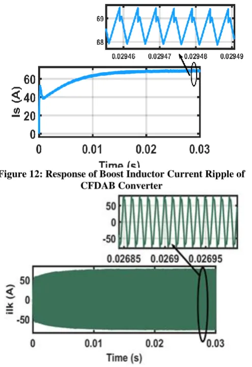
[image:5.595.46.557.48.820.2]Series inductor current of isolation transformer has small peak above the steady value due to the reverse diodes across the switches, which gives the ZCS turn-off.
Figure 12: Response of Boost Inductor Current Ripple of CFDAB Converter
Figure 13: Response of Leakage Inductor Current of CFDAB Converter
Fig. 14 shows the load regulation with same output response by changing the load resistors from 150Ω to 250Ω. In the same way, for tracking the reference signal with large variation from 200 V to 380 V proves good results are shown in Fig. 15 and Fig. 16. Also, primary and secondary side switching currents are shown in Fig. 17 and Fig. 18 respectively. It clearly indicates that the primary devices achieve ZCS and secondary switches achieve ZVS.
[image:5.595.304.559.58.635.2]Figure 14: Waveform of Load Regulation of CFDAB Converter
Figure 15: Waveform of Output Voltage with Different Reference Values
Figure 16: Response of Output Voltage Reference Tracking of CFDAB Converter
Figure 17: Responses of IT1 & IT3 Currents of CFDAB Converter
Figure 18: Responses of IT5 & IT7 Currents of CFDAB Converter
V. CONCLUSION
[image:5.595.49.297.85.446.2]The input of controller is only error signal, and this is one the prime interest of the PI model. Owing to high sensitivity of the latter to even small changes of duty cycle of primary side switches. This control design procedure gives an essentially stable high-level regulation and suited for this converter. Also, controller has found to be higher potent in terms of disturbance rejection and therefore, better satisfied for this application. MATLAB/SIMULINK perform the closed-loop simulations and it produced appropriate responses in terms of reference tracking action, line and load variation. The ultimate scope is to study the load flow of above proposed microgrid with the CFDAB converter and investigate the microgrid performance.
REFERENCES
1. Rocabert, J., Luna, A., Blaabjerg, F., & Rodriguez, P. (2012). Control of power converters in AC microgrids. IEEE transactions on power electronics, 27(11), 4734-4749.
2. Hossain, M., Pota, H., & Issa, W. (2017). Overview of AC microgrid
controls with inverter-interfaced generations. Energies, 10(9), 1300.
3. Dragičević, T., Lu, X., Vasquez, J. C., & Guerrero, J. M. (2016). DC
microgrids—Part I: A review of control strategies and stabilization
techniques. IEEE Transactions on power electronics, 31(7),
4876-4891.
4. Elsayed, A. T., Mohamed, A. A., & Mohammed, O. A. (2015). DC
microgrids and distribution systems: An overview. Electric Power Systems Research, 119, 407-417.
5. Justo, J. J., Mwasilu, F., Lee, J., & Jung, J. W. (2013). AC-microgrids versus DC-microgrids with distributed energy resources: A review. Renewable and sustainable energy reviews, 24, 387-405.
6. Lucia, O., Cvetkovic, I., Sarnago, H., Boroyevich, D., Mattavelli, P.,
& Lee, F. C. (2013). Design of home appliances for a DC-based nanogrid system: An induction range study case. IEEE Journal of Emerging and Selected Topics in Power Electronics, 1(4), 315-326.
7. Symanski, D. P. (2011, April). Residential & Commercial Use Of DC
Power. In UL & NFPA-Low Voltage Direct Current Workshop. Arlington, Virginia: EPRI.
8. Song, W., Hou, N., & Wu, M. (2018). Virtual Direct Power Control
Scheme of Dual Active Bridge DC–DC Converters for Fast Dynamic
Response. IEEE Transactions on Power Electronics, 33(2),
1750-1759.
9. Wu, T. F., Yang, J. G., Kuo, C. L., & Wu, Y. C. (2014).
Soft-switching bidirectional isolated full-bridge converter with active
and passive snubbers. IEEE Transactions on Industrial
Electronics, 61(3), 1368-1376.
10. Zhang, K., Shan, Z., & Jatskevich, J. (2017). Large-and small-signal
average-value modeling of dual-active-bridge DC–DC converter
considering power losses. IEEE Transactions on Power
Electronics, 32(3), 1964-1974.
11. Gammeter, C., Krismer, F., & Kolar, J. W. (2016). Comprehensive conceptualization, design, and experimental verification of a weight-optimized all-SiC 2 kV/700 V DAB for an airborne wind turbine. IEEE Journal of Emerging and Selected Topics in Power Electronics, 4(2), 638-656.
12. Xue, F., Yu, R., & Huang, A. Q. (2017). A 98.3% Efficient GaN Isolated Bidirectional DC–DC Converter for DC Microgrid Energy Storage System Applications. IEEE Transactions on Industrial Electronics, 64(11), 9094-9103.
13. Wu, H., Ding, S., Sun, K., Zhang, L., Li, Y., & Xing, Y. (2017). Bidirectional Soft-Switching Series-Resonant Converter With Simple PWM Control and Load-Independent Voltage-Gain Characteristics for Energy Storage System in DC Microgrids. IEEE J. Emerg. Sel. Top. Power Electron, 5, 995-1007.
14. Aguilar, O., Tapia, R., Valderrabano, A., & Minor, H. (2015). Design
and performance comparison of PI and adaptive current controllers for a WECS. IEEE Latin America Transactions, 13(5), 1361-1368.
15. Sira-Ramirez, H. (1991). Nonlinear PI controller design for
switchmode DC-to-DC power converters. IEEE Transactions on Circuits and Systems, 38(4), 410-417.
16. Zhang, Y., Wang, Z., & Liu, P. (2017, October). Optimized
modulation for current-fed dual active bridge to achieve high efficiency in wide load range. In Industrial Electronics Society, IECON 2017-43rd Annual Conference of the IEEE (pp. 1381-1386). IEEE.
17. Guacaneme, J., Garcerá, G., Figueres, E., Patrao, I., &
bridge DC to DC converter with average current control and load‐current feed‐forward. International Journal of Circuit Theory and Applications, 43(10), 1311-1332.
18. Alvarez-Ramirez, J., Cervantes, I., Espinosa-Perez, G., Maya, P., &
Morales, A. (2001). A stable design of PI control for DC-DC converters with an RHS zero. IEEE Transactions on Circuits and Systems I: Fundamental Theory and Applications, 48(1), 103-106. 19. Jaafar, A., Alawieh, A., Ortega, R., Godoy, E., & Lefranc, P. (2013).
PI stabilization of power converters with partial state
measurements. IEEE Transactions on control systems
technology, 21(2), 560-568.
20. Yau, H. T., Lin, C. J., & Liang, Q. C. (2013). PSO based PI controller design for a solar charger system. The Scientific World Journal, 2013.
AUTHORSPROFILE
A. Geetha is a Research Scholar in the department of Electrical and Electronics Engineering, Pondicherry Engineering College, Pondicherry University, Pondicherry, India. She received B.E., in Electrical and Electronics Engineering from Krishnasamy college of Engineering and Technology, Cuddalore, affiliated to Anna University, Chennai, India in April 2010 and Master's (M.E.,) in Power Electronics and Drives from Meenakshi College of Engineering, affiliated to Anna University, Chennai, India in May 2012. Her research interest includes DC-DC Converters, Control techniques and Power Systems.