International Journal of Innovative Technology and Exploring Engineering (IJITEE) ISSN: 2278-3075, Volume-8 Issue-7 May, 2019
Abstract: The sun is the most abundant source of renewable energy available on the earth. It provides enough energy in an hour to be used by the world for a whole year. Photovoltaic (PV) technology is one of the finest ways to capitalize the solar energy. Generally quiescent solar panels are used for harnessing the solar energy. Therefore, this paper includes the simulation, modeling procedures and results of a single axis solar tracking PV system prototype. The simulation of the tracking system has been provided using schematic modeling in proteus software. For compact size and reliability of the required circuits, PCB designing has been carried out in Eagle software. For controlling operations of the hardware, arduino is programmed and installed. For the prototype implementation, the design and construction of a microcontroller-based solar panel tracking system is also used. In this paper, the microcontroller named ‘Arduino UNO (Atmega 328)’ is utilized to give the signal to the motor that will move the solar panel along with the sun to gain maximum sunlight angle. A comparative report between the voltage output of the static solar panel and the single axis solar tracking system is also presented.
Index Terms: Single axis tracking; Solar panel; Arduino Software; PCB; Micro controller; LDR Sensor.
I. INTRODUCTION
With the availability problem of fossil fuel sources in the upcoming days, the investigators and financiers have focused in the area of different type of renewable energy sources for all around the world. Among the different type of renewable energy sources, hydropower, bio-fuel, wind power, tidal power, sun power and power from the earth are the important power sources. Because of the never ending property of renewable sources, they are encouraged for the replacement of fossil fuel sources. Among these energy sources, solar power is one of the most accessible modality. Due to the exploration and evolution growth, PV cell material with their better execution is improved and cost is also reduced. Therefore nowadays, this energy source has been widely used for housing purpose. Solar photovoltaic energy is very much predictable to become a main source of power in the future [1-3].
In solar PV systems, trackers assist to reduce the incidence position between the arriving sun light and the PV panel [4]. Due to this, the amount of energy produced by the installed solar panel is increased. Nowadays, many types of solar tracking systems are available in the market. In which, active solar tracker are widely used due to the more compatible, robust and more energy produced in comparison to others [5]. Active solar tracking devices can be classified into two main types: single-axis and dual-axis by means of PV panel rotation
Revised Manuscript Received on May 10 ,2019
Dr. Sandeep Gupta, Department of Electrical Engineering, JECRC University, Jaipur, Rajasthan 303905, INDIA
[6]. In single-axis tracking (SAT), PV modules are spin between east-west directions along with the Sun’s positions i.e. only one direction [7]. SATs confer practically good equilibrium between suppleness, simplicity and execution. When rotation of the surface is done around two axes simultaneously, it is two-axis tracking [12]. Two-axis tracking allows for the most precise orientation of the solar device, is reported to provide 40% gain in energy absorption, but it is more complex and costly. Such two-axis systems are also used for controlling astronomical telescopes [8-10].
This paper includes the simulation, modeling procedures and results of a single axis solar tracking PV system prototype. In the former sections step by step use of the software has been explained. In the middle sections the hardware used including the electronic components has been explained in detail with working description. In the later sections outcomes of the hardware prototype and simulation results are provided. For juxtaposing of the prototype and conventional single axis solar panel, comparative information is also provided. Finally in the last section, conclusion is summarized.
II. PROGRAMMINGDEVELOPMENT
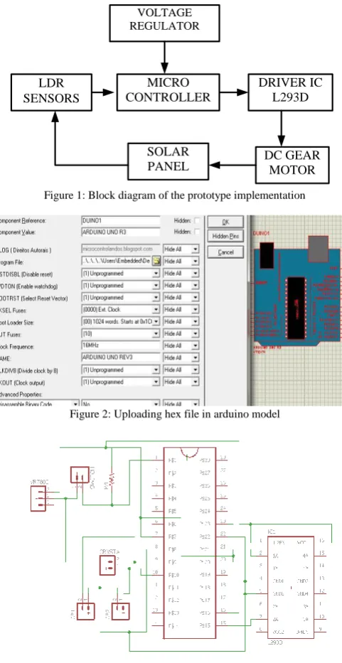
This paper work is divided into two parts, programming development and hardware development. Figure 1 shows the block diagram of the prototype implementation. Therefore programming development is explained in this section. In this paper, Arduino and Eagle software’s are used for programming part of the prototype implementation.
A. Arduino Software
Arduino software is used mainly for electronic design automation to create diagrammatic and electronic imprints modern PCB circuit boards designing. Arduino is the integrated development environment software. It contains the writing sketches, sketchbook, serial monitor, Boards, a text console and a text editor for coding [11]. Arduino schematic is not by default present in the proteus software and is added separately. The steps are given below:
i.Download the Arduino Library for proteus from internet. ii.Copy ARDUINO.LIB and ARDUINO.IDX files to C:\LabcenterElectronics\Proteus7Professional\LIBRAR Y
iii. Once you paste your file its over for ISIS. This has large collection of components in its library [12].
Maximum Sunlight Tracking Using Single Axis
Solar Panel Prototype with Simulation
VOLTAGE REGULATOR
LDR SENSORS
MICRO CONTROLLER
DRIVER IC L293D
SOLAR
PANEL DC GEAR MOTOR
[image:2.595.50.291.49.516.2]Figure 1: Block diagram of the prototype implementation
Figure 2: Uploading hex file in arduino model
Figure 3: Schematic diagram of PCB
B. Steps for Simulation
1. Open ISIS software then go to component mode and click P(pick from library)
2. Write arduino and select and click into the workspace and draw the required schematic diagram of Proteus that is needed to simulate.
3. Open the arduino IDE software, write the code in the text editor section and verify.
4. On verifying the hex file will be saved and its location would be provided.
5. Double click on the arduino board in ISIS and browse for the hex file to be uploaded as shown in Figure 2. 6. Click OK and click on the play button to start the
simulation.
The complete schematic diagram of PCB is shown in Figure 3. Components used in Schematic diagram are Arduino UNO (Atmega 328), IC (L293D), pull up switch, voltage regulator, resistor, ceramic capacitors and crystal oscillator.
C. Coding for Sun Light Tracking
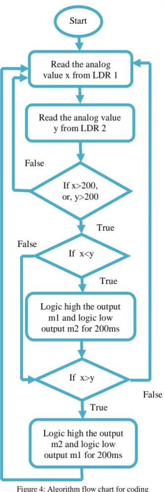
Algorithm flow chart for sun light tracking is described in the Figure 4. The followings coding are used for sun light tracking.
int ldr=A5; int ldr1=A4; int y; int x; int m1=10; int m2=9; void setup() { pinMode(ldr,INPUT); pinMode(ldr1,INPUT); Serial.begin(9600); pinMode(m1,OUTPUT); pinMode(m2,OUTPUT); }
void loop() { x=analogRead(ldr); Serial.println(x); y=analogRead(ldr1); Serial.println(y); if(x>200 || y>200)
{ if(y>x) {
digitalWrite(m1,HIGH); digitalWrite(m2,LOW); delay(200);
} else {
digitalWrite(m2,LOW); digitalWrite(m1,LOW); }
} else {
digitalWrite(m2,LOW); digitalWrite(m1,LOW); }
}
III. WORKINGDESCRIPTION
In this section the detailed working of the prototype is explained. The prototype is designed to work under specific environment conditions. A certain benchmark is already fixed for the light intensity above which this prototype will work. Therefore the model will not work when subjected to normal room light and torch would be helpful in working demonstration. Two LDRs (Light Dependent Resistances) have been used for sensing the light. The working principle of LDR has been explained in the previous sections. The microcontroller continuously gets power of 5V from the battery connected (which is a rechargeable battery recharged by PV panels in conventionally used solar panels). The program present in the void loop function of the microcontroller keeps executing infinite times till the microcontroller gets power supply. The microcontroller continuously checks the conditions provided in the infinite loop program. When an analog value greater than the pre-defined value falls on any of the two LDRs connected to the analog input terminals of the microcontroller, the digital output terminals to which motor driver IC L293D terminals are connected are enabled or disabled accordingly. Motor Driver IC L293D is a device which acts as an interfacing unit between the software and hardware. It is also connected to a battery which is used to provide power for driving motor. Depending upon which input terminal of the Driver IC is enabled by the output terminal of the microcontroller, the corresponding output terminal of the driver IC connected to the gear DC motor terminal is provided required voltage and the other terminal of the motor is grounded. The motor starts working accordingly until
[image:2.595.305.539.113.355.2]International Journal of Innovative Technology and Exploring Engineering (IJITEE) ISSN: 2278-3075, Volume-8 Issue-7 May, 2019
from the microcontroller.
True
True
True False
False
Logic high the output m2 and logic low output m1 for 200ms
Start
Read the analog value x from LDR 1
Read the analog value y from LDR 2
If x>200, or, y>200
If x<y
Logic high the output m1 and logic low output m2 for 200ms
[image:3.595.89.256.71.570.2]False If x>y
Figure 4: Algorithm flow chart for coding
There are total four conditions which govern the working of the motor. Let the light intensity analog values by LDR1 and LDR2 are x and y respectively and z is the benchmark analog input value.
a)If x<z and y<z the panel will be stable.
Both the output digital pins connected to the IC L293D will be low and hence both the terminals of the gear DC motor will be grounded.
b)If x>z and y<z the panel connected to the motor shaft will rotate in the direction of LDR1.
Output digital pin 9 connected to the IC L293D input pin 2 will be high and terminal 2 of the motor will get supply voltage. Terminal 1 will be grounded.
c)If y>z and x<z the panel connected to the motor shaft will rotate in the direction of LDR2.
Output digital pin 10 connected to the IC L293D input pin 7 will be high and terminal 1 of the motor will get supply voltage. Terminal 2 will be grounded.
d)If x>z and y<z and x=y the panel will be stable.
Both the output digital pins connected to the IC L293D will be low and hence both the terminals of the gear DC motor will be grounded.
According to the coding if condition (b) or (c) satisfies the motor will work for 200 μs and after 200 μs the microcontroller will again check all the conditions. A delay is provided for the smooth operation of the motor.
[image:3.595.304.558.396.542.2]The output of the solar panel is maximum, when the panel surface is perpendicular to the incident sunlight. In such case the intensity of the sunlight is same on both the LDRs. The rating of the prototype solar panel used is 6V. To demonstrate the use of the solar energy generated an additional charger circuit is designed and connected to the output of the solar panel. The charger circuit contains two electrolytic capacitors for the stable DC output and one 7805 voltage controller IC. The construction and function of IC 7805 has been discussed earlier. The output of the capacitor 2 is connected to USB port terminals. A mobile can be charged using a USB cable connecting the mobile with the USB port.
Figure 5: Proteus simulation schematic.
IV. OUTCOMESOFTHEPROTOTYPESOLAR
TRACKINGSYSTEM
A. Simulation Results:
To prepare the list of all the basic electronic components required and to check to working of the programming a simulation of the basic circuit for rotating the panel was designed in the Proteus ISIS simulation software as shown in the Figure 5.
Depending upon different values from the LDRs the direction of motor rotation will be determined. Let analog values by LDR1 and LDR2 are x and y respectively.
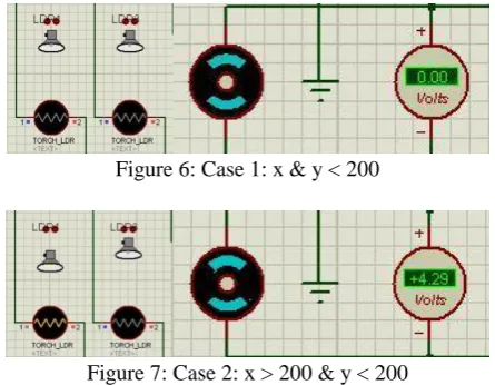
Case 1: x and y both are less than the predefined intensity 200.
shows zero reading and hence the motor is static as shown in Figure 6.
Figure 6: Case 1: x & y < 200
Figure 7: Case 2: x > 200 & y < 200
Case 2: x > 200 and y < 200
In this case the voltage shows positive reading (+4.29V) and hence the motor rotates clockwise as shown in Figure 7.
Case 3: x < 200 & y > 200
[image:4.595.313.543.50.228.2]In this case the voltage shows negative reading (- 4.29V) and hence the motor rotates anti-clockwise as shown in Figure 8.
Figure 8: Case 3: x < 200 & y > 200
Figure 9: Case 4: when x > 200 & y > 200 & x > y
Case 4: x > 200 & y > 200 & x > y
In this case the voltage shows positive reading (+ 4.29V) and hence the motor rotates clockwise as shown in Figure 9.
Case 5: x > 200 & y > 200 & y > x
In this case the voltage shows negative reading (- 4.29V) and hence the motor rotates anti-clockwise as shown in Figure 10.
Case 6 x > 200 & y > 200 & y = x
In this case the voltage shows zero reading and hence the motor is static as shown in Figure 11.
Figure 10: Case 5: when x > 200 & y > 200 & y > x
Figure 11: Case 6: when x > 200 & y > 200 & y = x B. Hardware Results
[image:4.595.62.285.86.259.2]The readings for both the static panel and single-axis tracker are taken for a single day from morning 8 am to evening 6 pm for every one hour as shown in Table 1 and graphical presentation is shown in Figure 12.
Table 1
Output results of prototype modules.
Sr. no.
Hour s
Static Panel Solar Tracking (Single Axis)
V mA mW V mA mW
1 08.00
AM 5.04 0.36 1.81 5.49 1.02 5.60
2 09.00
AM 5.10 0.70 3.57 5.67 1.06 6.01
3 10.00
AM 5.16 0.75 3.87 5.82 1.20 6.98
4 11.00
AM 5.82 1.09 6.34 5.91 1.43 8.45
5 12.00
PM 5.94 1.33 7.90 6.12 1.62 9.91
6 01.00
PM 6.18 1.54 9.52 6.48 1.92 12.4
4
7 02.00
PM 6.30 1.78 11.2
1 6.42 1.83 11.7
5
8 03.00
PM 5.82 1.63 9.49 6.15 1.76 10.8
2
9 04.00
PM 5.16 1.50 7.74 5.88 1.58 9.29
10 05.00
PM 4.98 1.28 6.38 5.55 1.46 8.10
11 06.00
PM 4.86 0.86 4.18 5.25 1.12 5.88 Average Power 6.55 8.66
[image:4.595.317.537.318.588.2] [image:4.595.54.288.381.558.2]International Journal of Innovative Technology and Exploring Engineering (IJITEE) ISSN: 2278-3075, Volume-8 Issue-7 May, 2019
0 8 .0 0 … 0 9 .0 0 … 1 0 .0 0 … 1 1 .0 0 … 1 2 .0 0 … 0 1 .0 0 … 0 2 .0 0 … 0 3 .0 0 … 0 4 .0 0 … 0 5 .0 0 … 0 6 .0 0 … O ut put pow e r (m W) Time Output power comparison Single
[image:5.595.62.293.60.193.2]axis tracker
[image:5.595.63.283.237.439.2]Figure 12: Comparison between output power of the static panel (fix) and single-axis tracker
Figure 13: Final prototype hardware design of single axis tracking system
0 2 4 6 8 10
Static panel Single axis tracking panel
A ve ra ge ou tp u t p o w er (m W )
Average power output comparison
Figure 14: Comparison between average output powers from different techniques
V. CONCLUSION
The paper provides a futuristic fission in harvesting of solar energy in a more efficient and suitable way. The paper has developed a small prototype which can open the doors of advancing the utilization of solar energy in near future at affordable prices. The solar tracker will help in future to make bigger systems which can be chronologically operated and helped in efficient tracking the position of the sun. The energy harvested can be used in number of home application, driving
engines which use electricity or diesel, or even in driving cars and micro- light aircraft. The objective of this paper is done to design and execute a small level prototype of tip-tilt single-axis solar tracking device with basic functions. The final result is a complete design of such a system, with functionality that met the design requirements. A comparative report between the voltage output of the static solar panel and the single axis solar tracking system is also provided. Finally we can say that implementation of this model on large scale will ensure that bigger models can be implemented using better and bigger motors.
REFERENCES
1.Prakash Kumar Sen, Krishna Awtar and Shailendra Kumar Bohidar: A Review of Major Non-Conventional Energy Sources. International Journal of Science, Technology & Management, vol. 4(01), 2015, pp. 20-25.
2.Sen PK, Awtar K, Bohidar SK A review of major non-conventional energy sources. IJSTM, vol. 4(01), 2015, pp. 20–25.
3.S. Gupta and A. Sharma, Global Scenario of Solar Photovoltaic (SPV) Materials. In Advanced Computational and Communication Paradigms Springer, Singapore, 2018, pp. 126-133.
4.Bansal, Ramesh, Distributed Renewable Energy Technologies. In Handbook of Distributed Generation, Springer International Publishing, 2017, pp. 3-67.
5.Samantha, A., R. Varma, and S. Bhatt, Chronological Single Axis Solar Tracker, International Journal of Engineering Trends and Technology (IJETT), vol. 21(4), 2013, pp. 204-207.
6.Ponniran, Asmarashid, Ammar Hashim, and Ariffuddin Joret. A design of low power single axis solar tracking system regardless of motor speed, International Journal of Integrated Engineering, vol. 3.2, 2011. 7.Chang, Tian Pau., Output energy of a photovoltaic module mounted on a
single-axis tracking system, Applied energy, vol. 86, no. 10, 2009, pp. 207-2078.
8.Mousazadeh, Hossein, et al., A review of principle and sun-tracking methods for maximizing solar systems output, Renewable and sustainable energy reviews, vol. 13.8, 2009, pp. 1800-1818.
9.Faranda, and Moris Gualdoni, Performance analysis of a single-axis tracking PV system, IEEE Journal of Photovoltaics, vol. 2, no. 4, 2012, pp.524-531.
10. Sandeep Gupta, An Evolution Review in Solar Photovoltaic Materials. Journal of Communications Technology, Electronics and Computer Science, vol. 20, 2018, pp.: 7-15.
11. Kassem, A., and M. Hamad, A microcontroller-based multi-function solar tracking system, Systems Conference (SysCon), 2011 IEEE International. 2011.
12. Kumar, Subhash, Design, development and performance test of an automatic two-Axis solar tracker system, India Conference (INDICON), 2011 Annual IEEE., 2011.
AUTHORSPROFILE
[image:5.595.61.284.476.626.2]