This is a repository copy of
Morphological wavelet domain image watermarking
.
White Rose Research Online URL for this paper:
http://eprints.whiterose.ac.uk/75658/
Proceedings Paper:
Bhowmik, D. and Abhayaratne, C. (2007) Morphological wavelet domain image
watermarking. In: 15th European Signal Processing Conference (EUSIPCO 2007).
EUSIPCO 2007, 3-7 September 2007, Poznan, Poland. EURASIP , Poznan, Poland , pp.
2539-2543. ISBN 978-83-921340-2-2
[email protected] https://eprints.whiterose.ac.uk/ Reuse
Unless indicated otherwise, fulltext items are protected by copyright with all rights reserved. The copyright exception in section 29 of the Copyright, Designs and Patents Act 1988 allows the making of a single copy solely for the purpose of non-commercial research or private study within the limits of fair dealing. The publisher or other rights-holder may allow further reproduction and re-use of this version - refer to the White Rose Research Online record for this item. Where records identify the publisher as the copyright holder, users can verify any specific terms of use on the publisher’s website.
Takedown
If you consider content in White Rose Research Online to be in breach of UK law, please notify us by
MORPHOLOGICAL WAVELET DOMAIN WATERMARKING
D. Bhowmik and G. C. K. Abhayaratne
Department of Electronic and Electrical Engineering, University of Sheffield
Sheffield S1 3JD, United Kingdom.
{
d.bhowmik, c.abhayaratne
}
@sheffield.ac.uk
ABSTRACT
Current digital watermarking methods based on the discrete wavelet transform use orthogonal wavelet kernels. In this paper, we discuss the use of morphological wavelets, which are a class of non-linear wavelets, in digital watermarking for scalable coded images. Three different scenarios for embed-ding the watermark, namely, 1) embedembed-ding only in the low pass subband (low-low), 2) embedding only in the high pass subbands (low-high, high-low and high-high) and 3) embed-ding in all subbands are considered to model popular wavelet domain watermarking methods. The performance of morpho-logical Haar and higher length median wavelets in terms of embedding and detection under content adaptation attacks, such as resolution and quality scalable decoding are shown. Morphological wavelets based watermarking shows a high ro-bustness against the content adaptation attacks, especially in resolution scalability, compared to the conventional orthogo-nal wavelets based watermarking.
1. INTRODUCTION
Digital watermarking is commonly used in content protection and authentication applications by means of hiding data that is used for verification in digital multimedia content. In digital watermarking for images, the watermark can be embedded on pixel domain or on frequency domain, which is usually real-ized by using a 2D transforms. The discrete wavelet transform (DWT) provides an intrinsic framework for multi resolution analysis of signals. Due to this reason and its ability to com-pact energy into a small number of coefficients, past years have seen the emergence of the wavelet transform domain watermarking algorithms [1]-[9]. They have shown great im-provements in data capacity and high imperceptibility com-pared to the previous watermark embedding techniques [10]. Due to the fact that the DWT is widely used in image com-pression, wavelet based watermarking enables joint water-marking and compression by addressing a common frame-work [1, 7].
Mr. Bhowmik would like to thank EPSRC for the EPSRC-BP Dorothy Hodgkin Postgraduate Award (DHPA) during the performance of this work
In all previously reported methods, only linear wavelet kernels have been used in watermark embedding and detec-tion in wavelet domain. In particular, Most algorithms used orthogonal transforms, such as, Haar or Daubechies length-4 (D4) wavelet kernels. Recently, there have been watermark-ing examples on extendwatermark-ing the choice of transform into M-band wavelets [8] and multi-wavelets [9]. Since the introduc-tion of the lifting factorizaintroduc-tion [11] of the DWT, which pro-vides a flexible framework to design non-linear wavelet trans-forms, non-linear wavelets have been used in image denois-ing and compression applications [12, 13, 14]. In the class of non-linear wavelets known as morphological wavelets, the linear lifting operators have been replaced by morphological operators [15, 16, 17].
An important requirement of digital image watermarking is that the watermark has to be robust to attacks, such as, adding noise, compression and content adaptation operations. With the emergence of scalable coding algorithms [18], the multimedia consumption chain uses scalable coded content in order to cater a wide range of usage requirements, such as var-ious resolutions and bit rates. Images are usually encoded at full resolution at high quality, then the bit streams are adapted to create new bitstreams according to the required quality and resolution to cater channel bandwidths and display ter-minal resolutions. As such adaptations are becoming more and more common, partly due to the availability of scalable coding and partly due to modern operational requirements, it is vital that the embedded watermarking can be detected in the adapted contents, thereby high robustness against content adaptation attacks. Such robustness is dependent on which subbands are used in embedding the watermark, the method of embedding and the choice of wavelet transform kernel.
2. MORPHOLOGICAL WAVELETS
The DWT is usually realized using filter banks. Every FIR filter bank can be decomposed into lifting steps by factor-ing its polyphase matrix usfactor-ing the Euclidean factorfactor-ing algo-rithm [11]. Non-linear wavelets are obtained by replacing the linear operations, such as weighted averaging, in lifting steps with non-linear operations. They can modify only the lift-ing step(s) affectlift-ing the low pass sub band (known as update step) [15], only the lifting step(s) affecting the high pass sub-bands (known as prediction step) [16] and the both types of lifting steps [17]. We show the design steps for two morpho-logical wavelet transforms: Morphomorpho-logical Haar (M-Haar) and Median lifting on quincunx sampling (M-QC).
2.1. Morphological Haar
Since non-linearities are introduced in the scaling function, we design the Morphological Haar based on the 2D non-separable decomposition. We start with a 2D input signala0with sam-plesa0
m,n, where mandncorrespond to sampling indices,
and its four 2D polyphase components (a, b, c, d), mapped by an invertible splitting operatorS2,i.e.(a, b, c, d) = S2(a0). The operatorS2forms a(2 0
0 2)sampling matrix and invertible mapping, called the lazy wavelet, as follows:
am,n=a02m,2n, bm,n=a02m+1,2n,
cm,n=a02m,2n+1 anddm,n=a02m+1,2n+1. (1)
We denote samplesam,n,bm,n,cm,nanddm,nbya,b,cand
d, respectively. The lazy wavelet is lifted to 2-D Haar using P3, P2, P1, Ulifting as follows to obtain output subbands,a′,
b′,c′andd′.
P3: d′= 1
2(d−(c+b−a)). (2)
P2: c′=c−(a−d′). (3)
P1: b′=b−(a−d′). (4)
U : a′ =1
2(a+b+c+d)
= 1
2(4a+ (a−a) + (b−a) + (c−a) + (d−a)).
(5)
It can be shown that,b−a= b′ −d′,c−a= c′ −d′ and
d−a=b′+c′. Hence we can rewrite the final update step as
U : a′= 2a+1 2(0 + (b
′
−d′) + (c′−d′) + (b′+c′))
= 2[a+1 4(0 + (b
′
−d′) + (c′−d′) + (b′+c′))] = 2[a+mean(0,(b′−d′),(c′−d′),(b′+c′))].(6)
We replace the mean operator with the median operator to obtain the 2D morphological wavelet transform as
a+median(0,(b′−d′),(c′−d′),(b′+c′)) =median(a, b, c, d). (7)
y1 x3
x y
y3 x1
y2 x2
Original Image
l
ll
h
hl
h0
h1
Level 1 Level 2
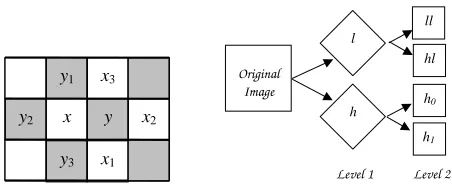
Fig. 1. Quincunx sampling: Left: Entries for prediction and update lifting steps,Right: Subbands after two levels of de-composition
The median operator, denoted by median(a, b, c, d), returns the median of the valuesa, b, c, d,i.e., it takes the average of the two intermediate values. Thus ifa≤b≤c≤dthen the median equals(b+c)/2. The inverse transform is obtained by reversing the order of operation and the operator of the lifting stepsP3P2P1U.
2.2. Median lifting on quincunx sampling
We design 2D non-separable wavelet transforms by using the quincunx sampling lattice with the corresponding sampling matrixD =¡1 1
1−1
¢
. Its determinant is 2 and thereby results in two polyphase components of the 2D signal each having dimensions equal to1/√2of the original signal dimensions. In the sequel we use¡mn
¢
= D¡i j ¢
, that ism =i+j and n=i−j. The splitting step for the 2D input signala0with samplesa0
m,nis given by
xi,j=a0m,nandyi,j =a0m+1,n. (8)
We denote samplexi,jbyxandyi,jbyyand we refer to their
respective neighbours as x1, x2, x3 and y1, y2, y3 as shown in Fig. 1. The white and gray boxes represent samples from xandypolyphase components, respectively. In this paper we are concerned with lifting steps of the form:
Prediction : y′ = y−median(x, x1, x2, x3), (9)
Update : x′= x+1
2median(y
′, y′
1, y2′, y′3). (10)
[image:3.595.329.555.78.173.2]existing quantisation and entropy coding methods designed for separable four subband decomposition schemes. The right column of Fig. 1 shows the subimages after two levels of de-compositions.
3. WAVELET BASED WATERMARKING
We categorize wavelet-based watermarking into 3 main groups depending on the subbands used for embedding the wavelet. They are 1) methods that use only the lowest frequency (LL) subband [1, 2], 2) methods that use only high frequency sub-bands [3, 4] and 3) methods that use all wavelet subsub-bands [5, 6]. We discuss an example from each category in below sec-tions.
3.1. Method 1: LL subband based watermarking
A blind watermarking scheme in this category is presented in [1] by etching a signature or a bit sequence in the wavelet domain. In this method, a non-overlapping3×1running win-dow is passed through the entire LL subband of the wavelet decomposed image. At each sliding position, a rank order sorting is performed on the coefficientsC1, C2andC3to ob-tain an ordered listC1< C2< C3. The median valueC2is modified to obtainC′
2as follows:
C2′ =f(α, C1, C3, w), (11)
wherewis a sample from the watermarkW andf()denotes a non-linear transformation.
For the extraction of watermark bit sequence, the DWT is performed on the received image. Then a rank order sorting is performed with a3×1running window to obtain sorted elementsC1, C2 andC3at each position. The watermarked bit associated with the particular window position is extracted as follows:
w= arg min
w∈(0,1)|C2−f(α, C1, C3, w)|, (12)
wheref()is the same as mentioned earlier. The extracted watermark is then authenticated by calculating the Hamming distancedbetween the original (W) and the extracted (W′)
watermark as follows:
d(W, W′) = 1
Nw Nw
X i=1
Wi⊕Wi′, (13)
whereNwis the length of the sequence and⊕represents the
XORoperation between the respective bits.
3.2. Method 2: LH, HL and HH subbands based water-marking
An example of this group is proposed in [3]. After the DWT, the watermark is embedded to the High frequency subbands
as follows:
Cm,n′ =Cm,n+αCm,n2 Wm,n, (14)
whereCm,nandCm,n′ are the original and modified
coeffi-cients, respectively andαis the parameter which controls the level of watermark,Wm,n.
The watermark detection process requires the watermarked as well as the original image. The DWT is applied to both the original and the received images. Then initially only the difference inHH in the first decomposition level (the high-est frequency subband) is compared for watermark detection. The similarity measure, s, shown in Eq. (15), is then per-formed between the difference and the original watermark.
s(W, W′) = W.W
′
√
W′.W′/
W.W
√
W.W ×100, (15)
whereW andW′ are the original and the extracted
water-marks, respectively. If the similarity measure is more than a specified threshold, the watermark is deemed to be detected. Otherwise the same procedure is followed withHHandHL subband combination orHH,HLandLHcombinationetc.
3.3. Method 3: All subbands based watermarking
We chose the wavelet based level adaptive thresholding al-gorithm proposed in [5] as an example to this category. In this case, the length of the watermark vector depends on the number of available significant coefficients which are deter-mined by level adaptive thresholding. For watermark embed-ding the DWT is performed and the significant coefficients are detected by comparing to the threshold, which is computed as follows:
Ti= 2⌊log2Ci⌋−1, (16)
whereTi andCi denote the threshold value and the largest
coefficient at theithdecomposition level, respectively. The
watermark is embedded to the selected coefficients as follows:
Cm,n′ =Cm,n+αCm,nWm,n, (17)
whereCm,ndenotes the chosen significant coefficients is the
selected wavelet coefficient,Wm,nis the watermark andαis
the scale factor which is adjusted according to the subband decomposition level. For the watermark detection purpose a similarity test as in Eq. (15) is carried out.
4. SIMULATION RESULTS
5000 5500 6000 6500 7000 7500 8000 8500 46.5 47 47.5 48 48.5 49 49.5 50 50.5 51 Method 1
data Capacity (bits)
PSNR(dB) Haar M−Haar D−4 M−QC 1 1 1 1 2 2 2 2 3 3 3 3 4 4 4 4 5 5 5 5
0 0.5 1 1.5 2 2.5 3
x 104 36 38 40 42 44 46 48 50 52 Method 2
data Capacity (bits)
PSNR(dB) Haar M−Haar D−4 M−QC 1 1 1 1 2 2 2 2 3 3 3 3 5 5 5 5 4 4 4 4
2000 2500 3000 3500 4000 4500 5000 5500 6000 42 44 46 48 50 52 54 Method 3
data Capacity (bits)
PSNR(dB) Haar M−Haar D−4 M−QC 1 1 1 1 2 2 2 2 3 3 3 3 4 4 4 4 5 5 5 5
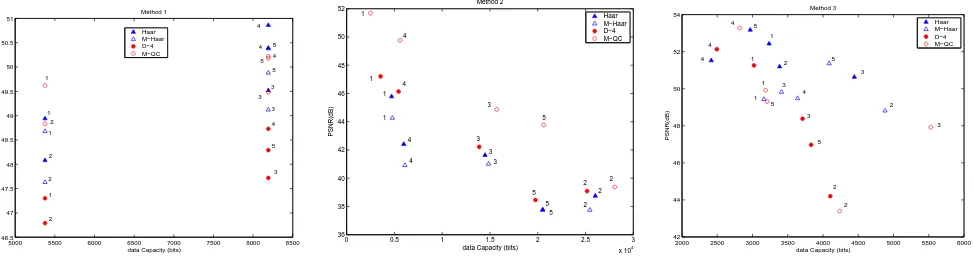
Fig. 2. Capacity-distortion plots. Numbers 1 to 5 represent the five images, Lenna, Mandril, Boat, Girl, and House, respectively (the last 3 are from the Kodak image set)
4.1. Embedding performance
In all cases, the DWT is applied on images to 2 decomposition levels, then the watermark is embedded in frequency domain and the inverse DWT is applied to get the watermarked im-age. We measured the data capacity of the watermark and the imperceptibility of the watermark and show in Fig. 2. The lat-ter was measured using the distortion added by walat-termark on the original image. It is evident from the plots that the Mor-phological wavelets result in capacity distortion performance comparable to that of orthogonal wavelets.
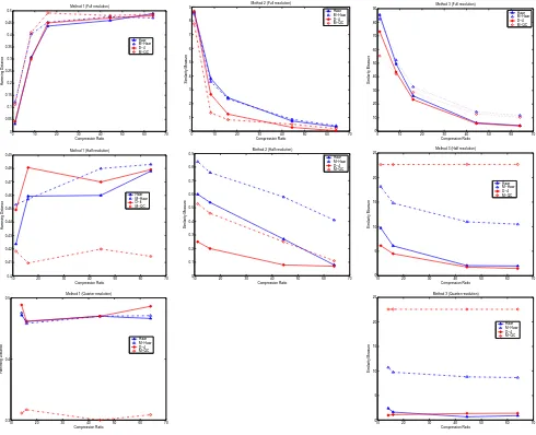
4.2. Robustness against content adaptation attack
We compressed the watermarked images using the JPEG2000 (Kakadu v.2.2 implementation available with [18]) to a high quality at full resolution. Then we modelled several content adaptation attacks by extracting new bit streams for full, half quarter resolutions at different bit rates and then decoding to obtain images with different qualities and resolutions.
The resolution adaptation makes the image size smaller than the original size and hence it needs to be up-sized for the cases where higher frequency bands are used for embedding. We resized the adapted image using 3 steps. Firstly, we cre-ate a matrix of zeros which has the same size of the original image and then scaled image is included in the top left cor-ner of the matrix. Secondly, an appropriate scaling (×2 for half resolution and×4 for quarter resolution) is performed. Finally, the 1 level (for half resolution) or 2 level (quarter res-olution) inverse DWT is performed using the same wavelet kernel used in watermark embedding.
The detection performances (Hamming distance for Method 1 and similarity measure for Methods 2 and 3) for different compression ratios and resolutions are shown in Fig. 3. A smaller Hamming distance or a higher similarity percentage yields better detection performance. We compare the perfor-mance of M-Haar and Q-MC with Haar and D-4, respectively. Morphological wavelets show better detection performances for half and quarter resolutions and at high compression
ra-tios, when compared to the corresponding orthogonal wav-elets of the same filter lengths.
5. CONCLUSIONS
In this paper, we have discussed the use of Morphological wavelets for wavelet domain watermarking. We have shown how to design non-separable 2D morphological Haar and median based wavelets on quincunx sampling. We analysed the performance by considering various methods of embedding based on the choice of subbands used for embedding. Morphological wavelets show capacity distortion performance comparable with that of orthogonal wavelets. They also show high robustness against resolution and quality scalability in content adaptation attacks.
6. REFERENCES
[1] L. Xie and G. R. Arce, “Joint wavelet compression and authen-tication watermarking,” inProc. IEEE ICIP, 1998, vol. 2, pp. 427–431.
[2] H. Inoue, A. Miyazaki, A. Yamamoto, and T. Katsura, “A dig-ital watermark based on the wavelet transform and its robust-ness on image compression,” inProc. IEEE ICIP, 1998, vol. 2, pp. 391–395.
[3] X. Xia, C. G. Boncelet, and G. R. Arce, “Wavelet transform based watermark for digital images,”Optic Express, vol. 3, pp. 497–511, Dec. 1998.
[4] M. Hsieh, D. Tseng, and Y. Huang, “Hiding digital watermarks using multiresolution wavelet transform,” IEEE Trans. on
In-dust. Elect., vol. 48, pp. 875–882, Oct. 2001.
[5] J. R. Kim and Y. S. Moon, “A robust wavelet-based digital wa-termarking using level-adaptive thresholding,” inProc. IEEE ICIP, 1999, vol. 2, pp. 226–230.
[6] Y. Seo, M. Kim, H. Park, H. Jung, H. Chung, Y. Huh, and J. Lee, “A secure watermarking for jpeg-2000,” inProc. IEEE ICIP, 2001, vol. 2, pp. 530–533.
[7] P. Su, H. M. Wang, and C. J. Kuo, “An integrated approach to image watermarking and jpeg-2000 compression,” J. VLSI
Signal Processing, vol. 27, pp. 35–53, Jan. 2001.
[image:5.595.66.553.75.204.2]0 10 20 30 40 50 60 70 0
0.05 0.1 0.15 0.2 0.25 0.3 0.35 0.4 0.45 0.5
Method 1 (Full resolution)
Compression Ratio
Hamming Distance
Haar M−Haar D−4 M−QC
0 10 20 30 40 50 60 70
0 1 2 3 4 5 6 7 8 9
Method 2 (Full resolution)
Compression Ratio
Similarity Measure
Haar M−Haar D−4 M−QC
0 10 20 30 40 50 60 70
0 10 20 30 40 50 60 70 80 90
Method 3 (Full resolution)
Compression Ratio
Similarity Measure
Haar M−Haar D−4 M−QC
10 20 30 40 50 60 70
0.4 0.41 0.42 0.43 0.44 0.45 0.46 0.47 0.48 0.49
Method 1 (Half resolution)
Compression Ratio
Hamming Distance
Haar M−Haar D−4 M−QC
10 20 30 40 50 60 70
0 0.1 0.2 0.3 0.4 0.5 0.6 0.7 0.8 0.9
Method 2 (Half resolution)
Compression Ratio
Similarity Measure
Haar M−Haar D−4 M−QC
10 20 30 40 50 60 70
0 5 10 15 20 25
Method 3 (Half resolution)
Compression Ratio
Similarity Measure
Haar M−Haar D−4 M−QC
10 20 30 40 50 60 70
0.3 0.4 0.5
Method 1 (Quarter resolution)
Compression Ratio
Hamming Distance
Haar M−Haar D−4 M−QC
10 20 30 40 50 60 70
0 5 10 15 20 25
Method 3 (Quarter resolution)
Compression Ratio
Similarity Measure
Haar M−Haar D−4 M−QC
Fig. 3. Watermark detection measurements under content adaptation attacks.Row 1: Full resolution,Row 2: Half resolution and
Row 3: Quarter resolution.Column 1: Method 1,Column 2: Method 2 andColumn 3: Method 3. Watermark cannot be detected at quarter resolution for Method 2 as only the high frequency subbands from a 2-level decomposition are used in watermarking
[9] A. Bouridane L. Ghouti and S. Boussakta, “High capacity wa-termarking using balance multiwavelet transforms,” inProc.
IEEE ICIP, 2005, vol. 1, pp. 977–980.
[10] P. Meerwald and A. Uhl, “A survey of wavelet-domain water-marking algorithms,” inProc. SPIE Security and
Watermark-ing of Multimedia Contents III, 2001, vol. 4314, pp. 505–516.
[11] I. Daubechies and W. Sweldens, “Factoring wavelet transforms into lifting steps,”J. Fourier Anal. Appl., vol. 4, no. 3, pp. 245– 267, 1998.
[12] R. Claypoole, G. Davies, W. Sweldens, and R. Baraniuk, “Non-linear wavelet transforms for image coding using lift-ing,” in31st Asilomar Conf. on Signals, Systems and
Com-puters, 1998, vol. 1, pp. 662–667.
[13] B. Pesquet-Popescu, H. Heijmans, G. C. K. Abhayaratne, and G. Piella, “Quantisation of adptive 2D wavelet decomposi-tions,” inProc. IEEE ICIP, 2003, vol. 3, pp. 209–212.
[14] G. C. K. Abhayaratne, “Wavelet filter banks with a 2D spatially adaptive low pass filter for scalable image coding,” inProc.
Picture Coding Symp., 2004, pp. 565–570.
[15] H. Heijmans and J. Goutsias, “Nonlinear multiresolution sig-nal decomposition schemes: Part II: Morphological wavelets,”
IEEE Trans. Image Processing, vol. 9, no. 11, pp. 1897–1913,
Nov. 2000.
[16] F. J. Hampson and J.-C Pesquet, “A nonlinear subband decom-position with perfect reconstruction,” inProc. IEEE ICASSP, 1996, vol. 3, pp. 1523–1526.
[17] G. C. K. Abhayaratne and H. Heijmans, “A novel morpholog-ical subband decomposition scheme for 2D+t wavelet video coding,” inProc. Int’l Symp. on Image and Signal Processing
and Analysis, 2003, vol. 1, pp. 239–244.
[18] D. S. Taubman and M. W. Marcellin, JPEG2000 Image
Com-pression Fundamentals, Standards and Practice, Springer,
[image:6.595.62.552.73.471.2]