Ames Laboratory ISC Technical Reports Ames Laboratory
6-1953
Correlation of Vickers hardness number, modulus
of elasticity, and the yield strength for ductile metals
Emil Arbtin Jr.
Iowa State College
Glenn Murphy
Iowa State CollegeFollow this and additional works at:http://lib.dr.iastate.edu/ameslab_iscreports Part of theCeramic Materials Commons, and theMetallurgy Commons
This Report is brought to you for free and open access by the Ames Laboratory at Iowa State University Digital Repository. It has been accepted for inclusion in Ames Laboratory ISC Technical Reports by an authorized administrator of Iowa State University Digital Repository. For more information, please [email protected].
Recommended Citation
Arbtin, Emil Jr. and Murphy, Glenn, "Correlation of Vickers hardness number, modulus of elasticity, and the yield strength for ductile metals" (1953).Ames Laboratory ISC Technical Reports. 50.
Correlation of Vickers hardness number, modulus of elasticity, and the
yield strength for ductile metals
Abstract
Hardness tests are widely used for determining comparative hardness numbers for metals, because of their simplicity and rapidity of operation. If appropriate charts or equations are known a given hardness number can be converted to other hardness numbers or to some of the mechanical properties.
Keywords Ames Laboratory
Disciplines
Ceramic Materials | Engineering | Materials Science and Engineering | Metallurgy
UNITED S7 ES ATOMIC ENERGY COMMISSION
ISC-356
CORRELATION OF VICKERS HARDNESS NUMBER, MODULUS OF ELASTICITY, AND THE YIELD STRENGTH FOR DUCTILE METALS
By
Emil Arbtin, Jr.
Glenn MurphyJune 1953
11
Tuhnl<al lnfa,maHan Senl<e, Oak Ridge,hn~euu
Subject Category, METALLURGY AND CERAMICS.
Work performed under Contract No. W-7405-eng-82.
This report has been reproduced directly from the best available copy.
Reproduction of this information is encouraged by the United States Atomic Energy Commission. Arrangements for
your republication of this document in whole or in part
should be made with the author and the organization he represents.
Issuance of this document does not constitute authority for declassification of classified material of the same or similar content and title by the same authors.
ISC-356
CORRELATION OF VICKERS HARDNESS NUNBER, MODULUS OF ELASTICITY, AND THE YIEU> STRENGTH FOR DUCTILE METALS*
by
Emil fArbtin, Jr. and Glenn Murphy
I. INTRODUCTION
Hardness tests are widely used for determining comparative hardness numbers for metals, because of their simplicity and rapidity of operation. If appropriate charts or equations are known a given hardness number can be converted to other hardness numbers or to some of the mechanical
p:-operties. ·
There are many definitions of hardness. Aristotle
(384-322
B.C.) defined the word 11hard" as that which does not cede to penetration through its surface(i).
H~gens in his Treatise on Light published in Leyden in1690
discussed hardness and mentioned that it varies with the direction on ti1e surface of crystals(9,
p.99).
Colonel Martels in1893
made a report to the French Commission on material testing(12,
p.11).
In this paper he defined hardness of metals as the resistance. to displacing the molecules at the surface and he measured hardness by the work required to displace a unit volume. This definition, he remarks, is special and applies to malleable materials which can have their ~olecules displaced without rupture. In the paper referred to~ ~1artel quoted the definition of hardness given b,y Osmond (12, p. 14) which reads: ~Hardness is that property possessed by solid bodies, in a variable degree, to defend the integrity of their form against causes of permanent deformation, and theintegrity of their substance against causes of division." Hardness has been defined
qy
various writers as resistance to abrasion, cutting, or indentation, and many methods have been devised to determine hardm ss by these means.Indentation hardness testing is important commercially in that it is widely used for the determination of the suitability of a material for a cettain purpose, maintainance of the uniformity of a product, and, because of the fact that it is non-destructive in nature, materials so tested can be used in service.
*This report is based on a M. S. thesis by Emil Arbtin submitted June, 1953.
2
ISC-356
The indentation hardness testing method was used in determining the hardness of metals reported in this paper. The Vickers method of
indentation hardness testing was chosen because it is the hardness test most used in research today, and the method of testing has been
standardized by various organizations.
The purpose of this thesis was to determine whether or not a relationship exists among a particular type of indentation hardness number, the Vickers hardness number, yield strength, and modulus of elasticity and to ascertain the effect of magnitude of load and time of load application on the Vickers hardness number.
II. REVIEW OF LITERATURE
A. History of Some Types of Hardness Tests
1. Indentation
Reaumur
(1683-1757),
who has been called the "father of hardness measurem:mt,tt seems to have been the first to establish a means o:fmeasuring ha:rdness, using the method of pressing the edges of two right angled prisms made of two different materials into one another
(17)
oSince the pressure was the sare in the two materials the results gave the relative hardness.
The physicist P.
Van
MUsschenbroeck(1729-1756)
studied hardness,according to Hugueny (8), with an apparatus consisting of a knife the handle of which was struck by an ivory ball. The nuniber of blows
required to cut through the material divided by its specific gravity was taken as a measure of its hardness. Van MUsschenbroeck was mostly
interested in the study of splitting woods, and the test was naturally suited to his needs. He also studied the hardness of some of the common metals, but his study was devoted rather to cleavage than to hardness.
In
1856
a Commission of American Artillery Officers conductedISC-356
A year or two later, in 1857~1858, Grace Calvert and R. Johnson
(3)
devised a hardness tester. This machine was of the penetrator type, the
penetrator being a truncated cone made to definite dimensions. The depth
of penetration was measured by a scale equipped with a vernier. The depth was fixed at
3.5
mm. and the load required to penetrate this depth was ~alled the hardness number. The work of these investigators was mostlyconfined t.o the softer metals. In their hardness scale~ cast iron was
taken as the unit.
In
1873
Bottone (2) also measured the hardness oi' malleable metals by a penetration test. For fragile substances which could not be testedby penetration method a wear test was substituted. For this
wear-hardness test Bottone employed a soft iron disc rotating at a given
velocity which was pressed against the obje.ct t.ested with a definite
pressure. He measured the time required to cut a certain depth and this
time 'qas taken as being proportional to hardness.
In
1879
A. Foppl(1854-1924)
following in the path of Reaumur andprobable also inspired
qy
the work of H. Hertz(1857-1894)
merely changedthe prisms used by the latter (7) for two semi-cylindrical bars that had their axes placed at right angles to one another. The bars were taen
pressed together. By measuring the area of contact of the flattened
surfaces and dividing the load by the area, he obtained the hardness
(6).
The Swedish metallurgist John August Brinell, then chief engineer of the Fagerrta Iron and Steel Works in Sweden, showed the now
well-known hardness tested bearing his name at the Paris Exposition of
1900.
The roothod used
qy
Brinell oonsisted in pressing a hard steel ball intothe surface of the metal to be tested. By measuring the dimensions of the
impression, then calculating the surface area a."'ld dividing the load by
this area, the hardness number i s found. As the load is usually measured
in kilograms. while the area is in square millimeters, the Brinell
hard-ness number is therefore the load in kilograms per square millimeter required to deform the material under test.
The Rockwell hardness tester i.s different from the Brinell hardness
tester in that a minor load is applied to the penetrator in order to have the penetrator firmely seated on the surface to reduce the effect of
surface condition. Next a major load is applied for a controlled length
of time. The Rockwell number is ba.sed on the difference between the depth
of penetration at major and minor loads. Details are given in Table 1 for various Rockwell tests and others.
The Vickers hardness tester is similar in I!V3thod to the Brinell test. A predetermined load is impressed at a point upon the specimen. The
4
ISc-3.56Table 1
Details of Some Hardness Tests*
Type of Designation Used Major Load
(kg.)
Type of Recommend~d
Penetrator Time of Test
Test of Scale for Used (sec.)
Vickers
Brinell
Brinell
Rockwell A
Rockwell B
Rockwell
c
Rockwell D
Rockwell E
Rockwell F
Metallic materials
1-120 Square based 10 diamond
pyramid
Ferrous }000 10 mm ball
Non-ferrous .500
Cold rolled 60
strip steel, case hardness steel, nitrided steel
Standard 100
Standard 1.50
100
Die castings 100
Annealed brass 6o
10 mm ball
Brale
1/16" ball
Brale
Brale
1/Btt· ball
l/l61t ball
10
30
See note below
See note below
See note below
See note below
See note below
See note below Minor Load (kg.) None None 10 10 10 10 10 10
~l"ote: The Rockwell machine is provided with a means of regulating the rate of application of the load. The machine should be adjusted so that When no specimen is in the machine at least five seconds are
consumed in the travel of the weight from its initial to its final position, using the one hundred kilogram load. If the 1.50 kilogram load is used, the time mould be four seconds as a mini~.
i!Reproduced from Murphy, G. and Arbtin, E. Rockwell and Vickers Hardness of Ames Thorium, p. 6. U.S. Atomic Energy Commission~
ISC-356
5
application and the removal of the load, after a predetermined interval,
are controlled· automatically. 'rhe internal mechanism of the Vickers
instrument consists mainly of a cam operated by a weight. The speed of rotation of this cam is controlled by an oil dashpot, and the movement applies the load to the diamond indenter. This cam applies, removes, and controls the duration of the load. The Vickers hardness number is found
t~ dividing the applied load by the surface area of the impression. Tables
are available that give the hardness number as a function of applied load
and diagonal of the impressionwhich is easily measured. The hardness
numbers obtained with the Vicker pyramid diarond, according to Williams
(20, p. 451), are practically constant, irrespective of the load applied.
The Vickers and Brinell hardness values on steel are practically identical
1,1p to a hardness of aoout three hundred. At higher hardness values the
Brinell falls progressively lower than the Vickers number and is not reliable above about six hundred Brinell, even with specially hardened balls. This irregularity is caused by flattening of steel balls under the heavy loads required for testing hard materials whereas the diamond shows no distortion.
2. Scratch
c.
Huygens (1629-1695) suggested that the optical properties ofIceland spar could be accounted for
qy
supposing the crystal structureas being composed of flat spheroidal molecules, and that at the surface
of the crystals the flattened spheroids were arranged directionally like the scales on a fi S1 ~ Therefore if a sharpened edge is moved in the
direction of the scales, it will slip over them, but i f it is attempted
to move the edge against the scales, it will catch against them and
slipping is impeded. He notes -this same effect in applying the scratch
method to the surface of Iceland spar. The scratch method is in fact one
i·my 'of demonstrating the direction in which the crystal is oriented
(9,
p.99).
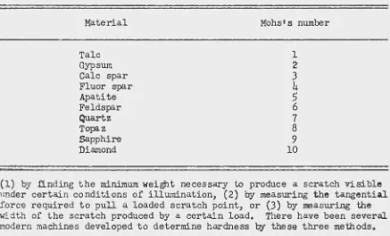
F. Mohs (1773-1839) devised a scratcl1 method of hardness testing
that ·is still in use by mineralogists today (15). Mohs' s scale was
divided into ten degrees of hardness;. the classification is shown in
Table 2. Its primary drawback is that the intervals are not well spaced
in the higher ranges of hardness, and also the inclination and orientation of the scratching point may effect the results. The procedure for making a Mohsts test is to apply the specimen to the hardest Mohs's mineral and then work downwards through the scale until the member in the scale which definitely allows itself to be scratched is reached.
Seebeck in ·1833 invented the sclerorooter, a hardness testing
instrument which carried a loaded point on Which rested a weight while
the whole was given a movement of translation producing a scratch (8).
6 ISC-356
Table 2
Mohs•s Scratch Hardness Scale
Material Mohs' s number
Talc Gypsum Calc spar Fluor spar Apatite Feldspar
Quartz
Topaz Sapphire Diamond
1
2 3
4
s
6
7
8 9
10
(1) by .finding the minimum weight necessary to produce a scratch visible nn.der certain conditions of illumination, (2) by measuring the tangential force required to pull a loaded scratch point, or (3) by measuring the
w~dth of the scratch produced by a certain load. There have been several modern machines developed to determine hardness by these three methods.
J. Dynamic
The dynamic method of hardness testing was developed comparatively recently and has achieved comparatively little industrial impr;;rtance yet. In 1893 Lieutenant Colonel Martel (12, p. 11) made a report t~ the French Commission on material testing. In this report Martel sets down the characteristics of dynamic hardness testing. His method of hardness testing consisted in striking a blo•• by means of a falling tup indenter on the oody for 'lvhich the hardness was to be determined and measuring the volume of the permanent deformation. Martel showed that the volume of the indentation produced by the falling tup was proportional to the height of faLl and the mass of the tup and independent of the shape (21). The Shore Scleroscope is a modern instrument very similar to the Martel instrument. In this method a small steel or diamond tipped weight is dropped on the specimen from a fixed height, and the height of rebound is measured.
B. Hardness Relationships
1. Hardness related to hardness
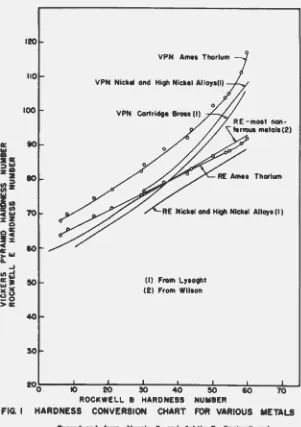
[image:10.549.51.488.115.379.2]ISC-·356 7
test. Each type of hardness test is influenced differently by the
properties of the material being tested. Different loads, different shapes of penetrators, homogeneity of the specimen and cold working properties of the metal all complicate the problem (ll). The data for hardness
conversion charts at present must be found by testing and a. different
chart .nust be made for each type of rootal, for example steel, brass, and
thorium. Figure l shows the general shape of various conversion curves
and illustrates the fact that a hardness conversion chart or graph for
one ~terial can not be used for other metals.
2. Hardness related to strength
Little work has been done on relating hardness to strength for
metals with the exception of steel. In 1930 the National Bureau of
Standards published a paper 1-rhich gave empirical formulas, vli th errors
to be expected of less than fifteen per cent, for determining the tensile
strength of steel from Rockwell B, Rockwell C, and Brinell hardness
numbers
(16).
The report stated that no discernible relationship wasfound bet-vreen the tensile strength of non-ferrous metals and their indentation number.
III. INVESTIGATION
A.
ObjectivesThe objects of this investigation were to determine~
l. Whether or not a relationship exists between the yield st-rength,
modulus of elasticity, and Vickers hardness nu;nber for vdrious
metals.
2o The effect of time and load on the Vickers hardness number for
several different metals.
B.
HypothesisMr'. Forrest E. Cardullo gave what seems to be one of the clearest
exposit:i.ons on the subject of hardness in Mechanical Engineering, October
1924 (4,
p. 638). Mr. Cardullo said:On reviewing the attempts which have been made to measure
hardness, we find that the methods employed cb not give results
which are a dimensional property of the mJ.teriaL That i~ .,
these results cannot be expressed in a rational term whic~,· :i.s the product of two or more of the real powers of the fundamental
8
a: I
affi
::liD
za en ::::I
cnZ
I:
CIAI:z:Z
0
oa:
s~
c
~"'
A. ..J
end
a:. ~l5 ~0
>a:
70
10
50
40
50
ISC-356
VPN Amea Thorium
VPN Nickel and Hi;h Nickel All011ll)
VPN Cortridge BroSI (I)
RE Nickel and Hi;h Nickel All011 (I)
(I) From L11o;ht (2) From Wllaon
20o 10 20 !0 40 50
ROCKWELL 8 HARDNESS NUMBER
FIG. I HARDNESS CONVERSION CHART FOR VARIOUS METALS
Reproduced from Murph1,G. and Arbtln,E. Rockwell and Vlcllera HoldMM of AIMI Thorium, p.IO. U.S. Atomic EM111
[image:12.551.121.422.85.512.2]ISC-3.56
Hohs' s scale of hardness gives a list of ten minerals, each of which can be scratched by the next harder and can scratch the next
softer. This is not a method of rreasuring hardness, but merely a method of c.."'mparing the relative hardness of two substances
differing widely in hardness.
While we have no accepted definition for hardness • • •
still it may not be impossible to identify it with some dimensional property of material. The following iine of reasoning may serve to clear up the situation to some extent.
When two bodies of the same size and form, and so disposed that their plane of contact is a plane of ~mmetry between them, are pressed together, the stresses and distortions produced in each will be equal, if they are of identical materials. The simplest case is of course where hm equal spheres are pressed together. If the spheres are of identical physical properties,
9
the area of contact between them will be a plane surface and circular in form. The bodies will be equal in hardness and the stresses and temporary and permanent deformations produced will be the same in each. If we take two spheres otherwise equal but of unequal elastic moduli and press them together, the area of contact will be a limited portion of a surface of revolution, and concave tm•ard the center of the rigid sphere • o o o • The normal pressure at any point in the surface of contact will be the scune for both spheres. If the elastic limit is the same for both materials and the pressure is increased till the elastic limit is exceeded, both spheres will be permanently deformed; but it is obvious that the one having the lower modulus of elasticity will be deformed more than the one having the higher modulus of elasticity.
Similarly, if two spheres of unequal moduli of elasticity are pressed upon a third one of much higher modulus of elasticity and elastic limit than either of the first two, the one having the lower modulus of elasticity will be deformed the most..
From this the writer concludes that one of the dimensional properties of which hardness is a function is the modulus of elasticity, and the higher the modulus of elasticity of a material, the greater its hardness will beo
Let us return to our first line of reasoning and consider two spheres of equal moduli of elasticity but of unequal
elastic limits, to be pressed together. Until the elastic limit of the weaker sphere is reached, the area of contact remains a plane circle. As soon as the elastic limit of the weaker
sphere is passed, the area of contact ceases to be a plane circle and becomes concave toward the center of the stronger sphere • • • • When the pressure is removed, i f the elastic limit of the stronger
sphere has not been exceeded, it will return to its original form, while the weaker one will be permanently deformed. If the elastic limit of both materials has been exceeded, both of the spheres ~~11
10
ISC-356
be deformed, the weaker one, however, suffering the greater deformation. Hence we may conclude that the hardness of a material is a function of its elastic limit, and more specifically of its compression elastic limit.
If we assume that the more rigid sphere has the lower elastic limit, we will observe the following phenomena as the pressure is increased:
Until the elastic limit of the weaker sphere is reached, the area of contact ~..rill be a curved surface concave toward the center of the more rigid but weaker of the two spheres. As the pressure
increases, the elastic limit will finally be reached at the center
of the surface of contact. Since the material there is supported by the surrounding material, the stresses are partly hydrostatic and partly shearing in their nature, and permanent deformation ':!ill not occur until the shear elastic limit has been passed. Because of its greater deformation this point may be reached first in the case o.f the stronger but less rigid sphere.
It is possible that the behavior of the two spheres under the conditions of this experiment will not be controlled exclusively by
their respective elastic limits and moduli, but will also be dependent on the forms of that portion of their stress-strain diagrams lying just beyond the elastic limit. In such a case the problem of making hardness a function of dimensional properties becomes rather hopeless. Furthermore it will probably be impossible to obtain consistent results when attempting to arrange a number of materials in a definite order of hardness when each is tested against all of the other, which is the simplest of all the problems in
connection with the determination of hardness.
The logical solution of the difficulty seems to be to take the
principal dimensional properties involved in the idea of hardness, to w~ite an equation of rational form connecting these properties with a numerical value for hardness, to determine experimentally whether this equation is consistent, and the value of its constants, and to accept this equation as the definition of hardness. It is obvious that the principal dimensional properties affecting the hardness of a homogeneous material are its elastic limit and modulus of elasticity. The simplest form of equation that we can write connecting hardness with these properties is
where H
-
-
numerical value of hardnessc
=
a constantE - modulus of elasticit,y
L
=
compression elastic limitISC-356
If now we prepare spheres of a number of different materials and investigate their behavior under the sort of test just
described, we may determine the values of m and n, and obtain a rational definition of hardness. It is probable that the value of both m and n lie pretty close to unity.
11
The author of this paper proposes that a similar type of phenomenon takes place when a rigid indenter is pushed into a ductile metal. That is -vrhen the indenter is pushed into a specimen and the rerulting
stresses developed in the material of the specimen do not exceed the elastic limit of the material, there will be no indentation in the
specimen when the load is removed from the indenter. If the elastic limit of the material is exceeded there will be plastic flow in the material under the indenter and when the load on the indenter is released there will be an indentation left in the specimen. For a given depth of penetration and shape of indenter the final depth and shape of the i ndentat.ion will be dependent on the modulus of elasticity and el<istic
limit of the material. Therefore it is assumed that the main properties of a homogeneous material that effect the hardness are the modulus of elasticity and elastic limit.
C. Method of Procedure
l. Materials
In considering the characteristics of the materials to be tested the following 1-mre taken into account~
l. The desirability of more than one type of metal in eac~ modulus of elasticity grouping.
2. A wide range of strengths in each modulus of elasticity grouping.
J.
The availability of the metals.It was decided to use twenty-one different metals in three modulus of elasticity groupings in the tests. This number included four sarr~les of aluminum, three of brass, three of copper, one of magnesium~ five of steel, one of tantalum, one of tin, and three of zinc.
2. Apparatus
There were two primary pieces of apparatus used in the tests. They were the Vickers pyramid hardness testing machine <ind a sixty thousand pound capacity Baldvlin Universal testing machine equipped with a
12 ISC-356
3.
Conduct of testsThe hardness test ::pecimens were prepared for testing by wet
surface grinding to a fine. finish, two parallel flats on each sample.
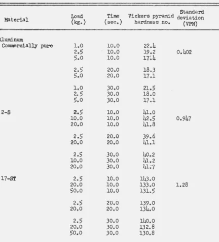
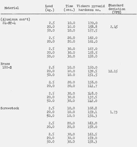
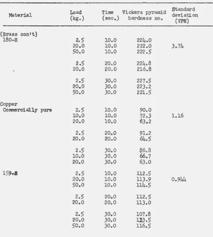
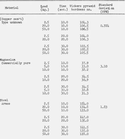
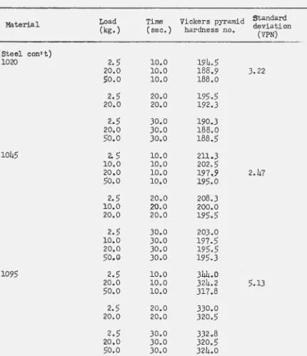
The test surface was carefully cleaned with a soft cotton cloth prior to testing. The test loads used varied from one to fifty kilograms depending on the hardness of the particular specimen. The times of load application used in testing were ten, twenty, and thirty seconds. At one load .. and time of load application, for each specimen, ten hardness t.ests were made. The average of two hardness tests was found for each of the other combination of time and load used. A total of eight hardness number averages was found for each specimen except tin. The low hardness of the tin specimen made it impossible to use a load higher than two kilograms in testing.
The tensile test specimens were made with a 0.252 inch diameter and sufficient length for the use of a one-inch gage length microformer extensometer. The tensile test was conducted with an upper crosshead velocity of three-thousands of an inch per minute until a unit strain of at least fifteen-thousands had been achieved, then the crosshead
velocity was increased to forty-thousands of an inch per minute for the remainder of the test. The crosshead velocity was measured by timing the displacement of the cross-head, which was measured by a dial micrometer. The tensile properties computed from the test results were the modulus of
elasticity, the yield strength (0.2% offset), and the ultimate strength in pounds per square inch.
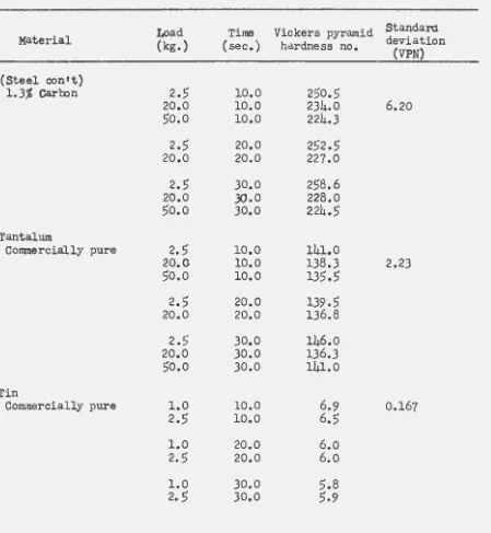
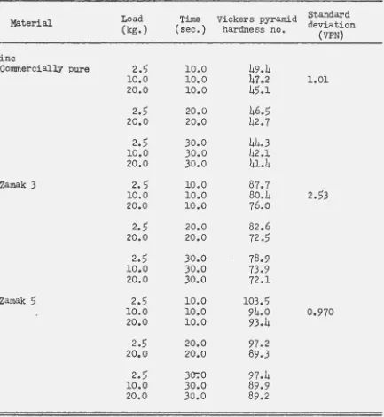
IT. RESULTS AND mSCUSSION
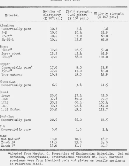
The results of the tensile and hardness tests are given in
Tables
3
and 4 respectively. In Figures 213,
and 4 the ultimate andyield strengths are shown plotted against the corresponding Vickers hardness number. The Vickers hardness number used in plotting was the
average of ten hardness tests. Three figures were used in plotting
the data in order that the data of each modulus of elasticity group
could be shown toeether and to reduce the confusion resulting from a large number of plotted points. The mean line shown in each figure was obtained by the least-squares method. In the analysis it was
assumed that the Vickers numbers were correct and the ultimate strength
numbers were subject to error. The equation of the mean line shown
in each figure was found to be:
1. Ultimate strength: -626 ~ 445(VPN) for m~terials with a
Material Aluminum Com~ercial1y pure 2-S 17-STa 24-ST-4 Brass 150·-Sa Screw stock
180-Ha
Copper
Corunercially purea
159-Sa
Type unknown
Ha.gnesium
Conrnercially pure
Steel
Armco
1020
1Ch5
109)
l.J% Carbon
Tantalum
Com::J.ercia1ly pure
Tin
Comrr1ercially pure
Zinc
Hot Rolleda Zamak 3a Zamak sa
ISC-3S6
Table 3
Tensile Test Data
Modulus of
elast~city
(X 10 psi.)
Yield strength,
0 •2
%
offset UltL~ate strength (X 103
psi.) (X 103 psi.)10.3 10.0 10.4 10.4 17.0 13.2 17.0 17.0 17.0 16.S 6.S
26.0
32.8 30.S 30.3 30.0 26.S 6.0 10.0 lLS 13.0 3.4 20.4 37.0 47.S 22.S 42.4 68.0s.o
17.0 49.3 3.4 37.469.0
60.4
.
92.h
49.3 66.01.6
10.2
23.0 31.7 S.622.9
60.068.0
S2.062.9
101.0u.s
47.079.9
100.4 167.0 111.767.S
2.4
18.7 34.040.7
13a Adapted from Hurphy, G. Properties of Engineering Materials. 2:nd ed. Scranton, Pennsylvania, International Textbook Co. 1947. Hardness specimens were from identical rods and plates as tensile specimens in reference cited.
[image:17.550.50.493.88.655.2]ISC-356
Table
4
Vickers Hardness Number Data
standard Load Time Vickers pyramid deviation
Material (kg.) (sec.) hardness no.
(VPN)
Aluminum
Commercially pure 1.0 10.0 22.4
2.5
10.0 19.2 0.4025.0
10.0 17~42.5 20.0 18.3
5.0
20.0 17.11.0 30.0 21.5
2.
5
30.0 18.05.0
30.0 17.12-S
2.)
10.0 41.010.0 10.0 42.5 0.947
20.0 10.0 41.8
2.5
20.0 39.62.0.0 20.0 41.1
2.5 30.0 40.2
10.0 30.0 41.2
20.0 30.0 41~7
17-ST
2.5
10.0 143.020.0 10.0 133.0 1.28
50.0
10.0 131.52.5
20.0 139.020.0 20.0 134.0
2.5 30.0 140.0
20.0 30.0 132.8
[image:18.543.45.477.100.576.2]ISC-356
15
Table 4 ( con't)
Load Time Vickers pyraJTP_d Standard Material
(kg.) (sec.) hardness no. deviation
(VPN)
(Aluminum conrt)
24-ST-4 2.5 10.0 170.0
20.0 10.0 158.8 2. 45
50.0 10.0 157.5
2.5 20.0 162.0
20.0 20.0 161.0
2.5 30.0 167
.o
20.0 30.0 158.5
50.0 30.0 158.0
Brass
180-S 2.5 10.0 150.0
20.0 10.0 139.5 12.15
50.0 10.0 151.5
2. 5 20.0 156.0
20.0 20.0 141.7
2.5 30.0 148.0
20.0 30.0 137.5
50.0 30.0 142.0
Screw stock 2.5 10.0 168.8
20.0 10.0 159.1 1. 73
so.o
10.0 156.32.5 20.0 163.0
20.0 20.0 158.0
I. 2.5 30.0 163.5
20.0 30.0 159.0
[image:19.550.42.483.97.569.2]16 ISC-3.56
Table 4 (con•t)
Load Time Vickers pyramid Standard
Material deviation
(kg.) ( sec.J hardness no.
(VPN)
(Brass con•t)
180-H 2 • .5 ~o.o 224.0
20.0 ~o.o 222.0 )\.74
.50.0 10.0 222 • .5
2 • .5 20.0 224.8
20.0 20.0 216.8
2 • .5 30.0 227 • .5
20.0 30.0 223.2:
.50.0 30.0 221..5
Copper
Commercially pure 2 • .5 10.0 90.0
10.0 10.0 72.3 1.16
20.0 10.0 63.2
2 • .5 20.0 91.2
20.0 20.0 64 • .5
2 • .5 30.0 6.6.8
10.0 30.0 66.7
20.0 30,0 63.0
1.59·1 2 • .5 10.0 ll2 • .5
20.0 10.0 113.9 0.944
.50.0 10.0 114 • .5
2 • .5 20.0 112 • .5
20.0 20.0 113.0
2 • .5 30.0 107.8
20.0 30.0 11,3 • .5
[image:20.547.51.487.89.574.2]ISC-356 17
Table 4 (contt)
Load Time Vickers pyramid Standard Material
(kg.) (sec.) hardness no. deviati. on
(VPN)
(Copper con•t)
Type unknown 2.5 10.0 104.3
20.0 10.0 106.5 0.724
50.0
10.0106.5
2.5
20.0 104.020.0 20.0 106.3
2.5 30.0 103.5
20.0 30.0 105.5
50.0 30.0
105.5
Magnesium
Commercially pure 2. 5 10.0 37.9
5.0 10.0 33.0 3.10
10.0 10.0 32.2
2.5
20.0 34.510.0 20.0 30.9
2.5
30.0 34.55.0
30.0 32.810.0 30.0 31.3
Steel
Armco
2.5
10.0 154.020.0 10.0 134.8 1.83
50.0
10.0 133.02.5 20.0 147.0
20.0 20.0 135.0
2.5 30.0 141.5
20.0 30.0 135.0
[image:21.546.42.480.100.588.2]18 ISC-356
Table
4
(con't)Load Time Vickers pyramid Standard
Material deviation
(kg.) (sec.) hardness no.
(VPN)
(Steel con•t)
1020 2 • .5 10.0 194 • .5
20.0 10.0 188.9 3.22
$0.0 10.0 188.0
2 • .5 20.0 19.5 •
.s
20.0 20.0 192.3
2 • .5 30.0 190.3
20.0 30.0 188.0
.so.o
30.0 188 • .5104.5 2..5 10.0 211.3
10.0 10.0 202 • .5
20.0 10.0 197 ..
9
2.47.so.o
10.0 l9.5.b2 • .5 20.0 208.3 10.0 .20.0 200.0 20.0 20.0 195 • .5
2 • .5 30-.0 203.0 10.0 30.0 197 • .5 20.0 30.0 19.5 • .5 50-"G 30.0 19.5.3
109.5 2 • .5 10.0 344.0
20.0 10.0 324.2 5.13
.so.o
10.0 317.82 • .5 20.0 330.0 20.0 20.0 320 • .5
2 • .5 30.0 332.8 20.0 30.0 320 • .5
[image:22.551.53.483.94.593.2]ISC-356 19
Table
4
(con1t)Load Time Vickers pyramid Standard.
Material (kg.) (sec.) hardness no. deviation
(VPN)
(Steel con't)
1.3% caroon 2.5 10.0 250.5
20.0 10.0 234.0 6.20
50.0 10.0 224.3
2.5 20.0 252.5
20.0 20.0 227
.o
2.5 30.0 258.6
20.0 3().0 228.0
50.0 30.0 224.5
Tantalum
Commercially pure 2.5 10.0 141.0
20.0 10.0 138.3 2.23
50.0 10.0 135.5
2.5 20.0 139.5
20.0 20.0 136.8
2.5 30.0 146.0
20.0 30.0 136.3
50.0 30.0 141.0
Tin
Co~nercially pure 1.0 10.0 6e9 0.167
2.5 10.0 6.5
1.0 20.0 6.0
2. 5 20.0 6.0
1.0 30.0 5.8
[image:23.551.44.493.91.578.2]20 ISC-3.56
Table 4 {contt)
Load Time Vickers pyramid Standard
Material deviation
(kg.) (sec.) hardness no.
(VPN)
Zinc
Commercially pure 2 • .5 10.0 49.4
10.0 10.0
47 ..
2 1.0120.0 10.0 4.5.1
2 • .5 2.0. 0 46 • .5
20.0 20.0 42.7
2 • .5 30.0 44.3
10.0 30.0 42.1
20.0 30.0 41.4
Zamak 3 2 • .5 10.0 87.7
10.0 10.0 80.4 2 • .53
20.0 10.0 76.0
2 • .5 20.0 82.6
20.0 20.0 72 • .5
2 • .5 30.0 78.9
10.0 30.0 73.9
20.0 30.0 72.1
Zamak .5 2 • .5 10.0 103 • .5
10.0 10.0 94.0 0.970
20.0 10.0 93.4
2..5 20.0 97.2
20.0 20.0 89.3
2 • .5 30':0 97.4
10.0 30.0 89.9
[image:24.549.57.490.102.573.2].,
0 llC X 0z
LIJ a:: <t ::) 0 (/) a:: LIJ ~ (/) 0z
:;:) 0 ~z
X....
"
z
LIJ a::
....
(/) LLI~
~~
: l"b
llC X 0z
LIJ a:: <t ::) 0 (/) a:: LIJ ~ (/) 0z
::) 0 ~z
-....
LLI (/) Lt. Lt. 0 ~"'
d
-
X....
"
z
LIJ a::....
(/) 0 .J LIJ ~FIG. 2
ISC-356
21• Ultimate strenoth
o
Yield strenoth (0.2•1.
offset)Ultimate strenoth =-626 +445(VPN)
I 0
40
0
0
•
00
50
1e
aoo
VICKERS PYRAMID HARDNESS NUMBER
STRENGTH VS HARDNESS
NUMBER FOR MATERIALS
WITH A MODUWS OF ELASTICITY OF APPROX
'
[image:25.545.55.485.50.664.2]22
%
(,)
~
.,
0%
(,)
z
w
a::
c( ::)
0
{/)
a::
w
Q.
~
{/)
-a
....
z
w
::) {/)0 ~
Q.
~
z
~-"'
%
d
t;
-z
%w
....
a::
0t-
z
{/)
w
0:::
w
....
t(
{/)2
a
-
_,
~
w
-::)
>-ISC-356
• Ultimate strenoth .
o
Yield strenoth (0.2•t.
offset)Ultimate strenoth
=
554
+423 (VPN)•
0
0
0
0
0
o~--~4~0----~.~o----~~--~~--~20~0~--~24+0~
VICKERS PYRAMID HARDNESS NUMBER
FIG. 3.
STRENGTH VS. HARDNESS NUMBER FOR MATERIALS
WITH A MODULUS OF ELASTICITY OF
[image:26.548.20.532.13.680.2]ISC-
3
5
6
23•
180
-
MJ:
•
Ultimate strength(.)
~ 16
""
o
Yield strength (0.2°/o offset).•
a::
Ultimate strength a -23,200+
583(VPN)0 C(
-
.
:::)0
M
(/) 14
J:
a::
(.)
z
""
Q.""
(/)a::
0 12C(
~
:::)
0 0
(/) Q.
a::
z
""
Q.-(/) t- 0
0
~
z
LL.:::) LL.
0 0 8
Q.
.,.
z
~
0~
-
J: 6 0z
t-""
(!)a::
z
0t;
""
a::
•
t- 4
""
(/) 0ti
0~ ..J
6
""
-:::)
>
20
0~--~~~--~~~--~,~50~--~~--~2~50~--~~--~VICKERS PYRAMID HARDNESS NUMBER
FIG. 4
STRENGTH VS. HARDNESS NUMBER FOR MATERIALS
WITH
A
MODULUS OF ELASTICITY OF APPROXIMATELY
[image:27.549.47.490.54.671.2]24
ISC-J56 •2. Ultimate strength : 554 "' 423(VPN) for materials with CL modulus
of elasticity approximat~ly equal to 17~000,000 psi.
3.
Ultimate strength =-23,200 ... 585(VPN) for materials with a modulusof elasticity approximately equal to 30,000,000 psi.
In these equations the ultimate strength is in pounds per square inch
and VPN is the Vickers pyramid hardness number. The slopes of the
lines and the intercepts of the lines o;n the axes as given by the equations do not increase with an increase in the modulus of
elasticity. ·The equation for metals with a modulus of elasticity of
about 10,000,000 psi. agre·es wi. th data determined by the author for
thorium, \dthin the limitations of both sets of data. ~o published
data or equation could be found for metals with a modulus of elasticity of about 17,000,000 psi. for comparison with the determined equation.
The equation for metals with a modulus of elasticity of CLbout 30,000,000
psi. agrees, within the accuracy of the data used to determine the equation, with data published for steels by Williams {20, p. 463).
In Figure
5
is shown a plot of Vickers hardness number versus thetest load for the three testing times for the 1045 steel hardness specimen. The hardness data for the other specimens would show
similar curves if plotted as in Figure
S.
Because the Vickers hardnessnumber is dependent upon the applied load: and tine of t-esting the
author suggests that in reporting Vickers hardness numbers both the
load and testing time be stated.
The equations listed are limited in accuracy by the snall number of points used to determine each equation, by the accuracy of the tensile test data, and by the accuracy of the hardness test data. The tensile test data would have been more accurate if more than one test had been
made on each material and an average of the tests reportedo The
homogeneity of the tensile and hardness test specimen has a large effect
on the data obtained in the test. The standard deviation of ten hardness
tests for each metal was found for an indication of the homogeneity of each metal and they are tabulated in Table 4. It is apparant that the standard
deviations differ{·considerably in magnitude and hence the metals differ
substantial~ in homogeneity.
V. SUGGESI'IONS FOR FURTHER STUDY
There are many avenues for research in the hardness field.
Practically nothing of an analytical nature has been done. An
analysis of the indentations caused by variously shaped indenters
would be most helpful for the construction of conversion charts of
0
~
2000
<(
0::
>
~(/)
0::
w
~
0
->
ISC-356
o
Testino time of ten seco.nds.G Testino time of twenty seconds.
e
Testino time of thirty seconds.25
1900
0~----,~0----~2~0----~30~--~40~--~50~--~60~--TEST LOAD IN KILOGRAMS
FIG. S
VICKERS PYRAMID HARDNESS NUMBER VS. TEST
[image:29.548.50.482.57.654.2]26
ISC-356
using the photoelastic method would be helpful to the rolution of the hardness problem. The effect of time of testing on the hardness number, for variously shaped indenters, needs more investigation, particularly for long time intervals of testing.
Very little work has been done orr-·an analysis of the dynamic hardness test and i t offers many problems to be solved.
VI. SUMM~RY AND CONCLUSIONS
The object of this investigation was to determine whether or not a relationship existed between the yield strength, modulus of elasticity, and the Vickers hardness number for various metals. Tests were also performed to determine whether or not the Vic~ers hardness number was independent of the time interval and applied load used in testing.
Equations were derived for determining the ultimate strength of a metal from .its Vickers hardness number for three modulus of
elasticity ranges.
Within the limits of this investigation the following oonclusions seem reasonable to the author:
1. There is no discernible relationship between the yield strength and the Vickers hardness number.
2. There is a linear relationship between the ultimate strength and the Vickers hardness number for materials with approxi-mately the same modulus of elasticity. The relationship can be used for predicting the ultimate strength of a metal from the knowledge of its Vickers hardness number.
3.
The Vickers hardness number is dependent on the length of time of the testing cycle and the magnitude of the applied load.VII.
Lisr
OF REFERENCES1. Aristotle, Meteorologie, Book IV, Chap. IV, translated by
~rthelemy-Baint Hilaire. (Original not available for
examination: cited by Landau, D. Hardness, p.
7.
N.Y., The Nitralloy Corp. 1943.)2. Bottone, S. Relation entre le poids atomique, le poids
ISC-356
Landau, D. Hardness, p. 10. N.Y., The Nitralloy Corp. 1943.)
3.
Calvert, F. C. and Johnson, R. On the Hardness of Metals and Alloys. Literary and Philosophical Society of Manchester.15~113-121. 1857-1858. (Original not available for examination; cited b,y Landau, D. Hardness, p. 10. N.Y., The Nitralloy Corp. 1943.)
4. Cardullo, F. E. The Hardness of Metals and Hardness Testing. Mechanical Engineering. 46: 6)8-639. 1924.
5.
Commission d'Officiers de l'Artillerie Americaina. Reports of Experiments on the Strength and Other Pro:Perties of Metals for Cannon. 1856. (Original not available for examination; cited by Landau, D. Hardness, p. 9. N.Y., The Nitralloy Corp. 1943.)6. F6ppl, A. Uber die mechanische Harte der Metalle, besonders der stahls. Annalen der Physik. 63:103-108. 1897.
7. Hertz, H. Uber die Beriihrung fester elastischer K'Orper.
Journal fur die Reine und Angewandte Mathematik. 92:156-171. 1881.
B. Hugueny, M. F. Recherches exp~rimentales Sur la Duretl des Corps. Pa.ris, Gauthier-Villars. 18~5. (Original not available for examination; cited by Landau, D. Hardness, p. 9. N.Y., The Nitralloy Corp. 1943.)
9. Huygens,
c.
Trait~ de la Lumiere. Translated into Englishb.1
Thompson, S. P. Treatise on Light. Chicago, University of Chicago Press. 1945.
10. Landau, D. Hardness. N.Y., The Nitralloy Corp. 1943.
11. :cysght, V. E. Indentation Hardness Testing. N.Y •. , Reinhold PubliEhing Corp. 1949.
12. Martel, Lieutenant Colonel Sur la mesure de la duret~ des
m~taux ~-la p~netration au moyen d•empreintes obtenues par chock avec un couteau pyramidal. Paris, Commission
d~s Methodes d•essais des Mat~r1aux de Construction.
3:
Part A, 261. 1895. (Original not available for examination; cited by Landau, D. Hardness, p. 11, 14. N.Y., The Nitralloy Corp. 1943.)28 ISC-356
13. Murphy, G. Properties of Engineering Materials. 2nd. ed.
Scranton, Pennsylvania, International Textbook Co. 1947.
14. MUrphy, G. and Arbtin, E. Rockwell and Vickers Hardness of
Ames Thorium. U.S. Atomic Energy Commission. Iowa State
College-316. 1953.
15. O'Neil, H. The Hardness of Metals and its Measurement.
London, Chapman and Hall Ltd. 1934.
16. Petrenko, 5. N. Relationships Between Rockwell and Brinell
Numbers. U.S. Bureau of Standards, Journal of Research.
5:19-50. 1930.
17. Reaumur, R. A. L'art de convertir le fer forge en acier, et
ltart dtadoucir le fer .fondu, pu de faire des ouvrages de
fer dondu, aussi finis gue le fer forge. Paris, Michel
Brunet. 1722. (Original not available for examination;
ci. ted by Landau, D. Hardness, p. 8. N.Y., The Nitralloy
Corp. 1943.)
18. Seebeck. Ueber Harteprufung an Crystallen. Berlin, Unger.
1833. (Original not available for examination; ci. ted by
Landau, D. Hardness, p. 9. N.Y., The Nitralloy Corp. 1943.)
19. Tabor, D. The Hardness' of Metals. OXford, Clarendon Press.
1951.
20. Williams, S.R. Hardness and Hardness Measurement~ Cleveland,
The Arerican Society for Metals. 1942.
21. Williams, S. R. Present Types of Hardness Tests. Society for Testing Materials Proceedings. 1943.
American 43:803-856.
22. Wilson. Chart 38. N.Y., Wilson Mechanical Instrument Co.,
Inc. 1942.
23. Worthing, A. G. and Geffner, J. Treatment of Experimental
Data. N.Y., John Wiley and Sons, Inc. 1943.