w w w . s y n g r e s s . c o m
Syngress is committed to publishing high-quality books for IT Professionals and delivering those books in media and formats that fit the demands of our customers. We are also committed to extending the utility of the book you pur-chase via additional materials available from our Web site.
SOLUTIONS WEB SITE
To register your book, visit www.syngress.com/solutions. Once registered, you can access our [email protected] Web pages. There you will find an assortment of value-added features such as free e-booklets related to the topic of this book, URLs of related Web site, FAQs from the book, corrections, and any updates from the author(s).
ULTIMATE CDs
Our Ultimate CD product line offers our readers budget-conscious compilations of some of our best-selling backlist titles in Adobe® PDF form. These CDs are the perfect way to extend your reference library on key topics pertaining to your area of expertise, including Cisco Engineering, Microsoft Windows System
Administration, CyberCrime Investigation, Open Source Security, and Firewall Configuration, to name a few.
DOWNLOADABLE EBOOKS
For readers who can’t wait for hard copy, we offer most of our titles in download-able Adobe PDF form. These eBooks are often availdownload-able weeks before hard copies, and are priced affordably.
SYNGRESS OUTLET
Our outlet store at syngress.com features overstocked, out-of-print, or slightly hurt books at significant savings.
SITE LICENSING
Syngress has a well-established program for site licensing our eBooks onto servers in corporations, educational institutions, and large organizations. Contact us at [email protected] for more information.
CUSTOM PUBLISHING
Many organizations welcome the ability to combine parts of multiple Syngress books, as well as their own content, into a single volume for their own internal use. Contact us at [email protected] for more information.
Configuring
SonicWALL
Firewalls
Chris Lathem
Benjamin W. Fortenberry
Kevin Lynn
Daniel H. Bendell
Joshua Reed
Bradley Dinerman
Technical Editortion (collectively “Makers”) of this book (“the Work”) do not guarantee or warrant the results to be obtained from the Work.
There is no guarantee of any kind, expressed or implied, regarding the Work or its contents.The Work is sold AS IS and WITHOUT WARRANTY.You may have other legal rights, which vary from state to state.
In no event will Makers be liable to you for damages, including any loss of profits, lost savings, or other incidental or consequential damages arising out from the Work or its contents. Because some states do not allow the exclusion or limitation of liability for consequential or incidental damages, the above limitation may not apply to you.
You should always use reasonable care, including backup and other appropriate precautions, when working with computers, networks, data, and files.
Syngress Media®, Syngress®, “Career Advancement Through Skill Enhancement®,” “Ask the Author UPDATE®,” and “Hack Proofing®,” are registered trademarks of Syngress Publishing, Inc. “Syngress:The Definition of a Serious Security Library”™, “Mission Critical™,” and “The Only Way to Stop a Hacker is to Think Like One™” are trademarks of Syngress Publishing, Inc. Brands and product names mentioned in this book are trademarks or service marks of their respective companies.
KEY SERIAL NUMBER
001 HJIRTCV764 002 PO9873D5FG 003 829KM8NJH2 004 P762ABL8D2 005 CVPLQ6WQ23 006 VBP965T5T5 007 HJJJ863WD3E 008 2987GVTWMK 009 629MP5SDJT 010 IMWQ295T6T PUBLISHED BY Syngress Publishing, Inc. 800 Hingham Street Rockland, MA 02370
Configuring SonicWALL Firewalls
Copyright © 2006 by Syngress Publishing, Inc. All rights reserved. Printed in Canada. Except as permitted under the Copyright Act of 1976, no part of this publication may be reproduced or distributed in any form or by any means, or stored in a database or retrieval system, without the prior written permission of the publisher, with the exception that the program listings may be entered, stored, and executed in a com-puter system, but they may not be reproduced for publication.
Printed in Canada 1 2 3 4 5 6 7 8 9 0 ISBN: 1-59749-250-7
Publisher: Andrew Williams Page Layout and Art: Patricia Lupien
Acquisitions Editor: Jaime Quigley Indexer: J. Edmund Rush
Technical Editor: Lars Hansen, Brad Dinerman Cover Designer: Michael Kavish
Acknowledgments
v Syngress would like to acknowledge the following people for their kindness and sup-port in making this book possible.
Syngress books are now distributed in the United States and Canada by O’Reilly Media, Inc.The enthusiasm and work ethic at O’Reilly are incredible, and we would like to thank everyone there for their time and efforts to bring Syngress books to market:Tim O’Reilly, Laura Baldwin, Mark Brokering, Mike Leonard, Donna Selenko, Bonnie Sheehan, Cindy Davis, Grant Kikkert, Opol Matsutaro, Steve Hazelwood, Mark Wilson, Rick Brown,Tim Hinton, Kyle Hart, Sara Winge, C. J. Rayhill, Peter Pardo, Leslie Crandell, Regina Aggio, Pascal Honscher, Preston Paull, Susan Thompson, Bruce Stewart, Laura Schmier, Sue Willing, Mark Jacobsen, Betsy Waliszewski, Kathryn Barrett, John Chodacki, Rob Bullington, Aileen Berg, and Wendy Patterson.
The incredibly hardworking team at Elsevier Science, including Jonathan Bunkell, Ian Seager, Duncan Enright, David Burton, Rosanna Ramacciotti, Robert Fairbrother, Miguel Sanchez, Klaus Beran, Emma Wyatt, Chris Hossack, Krista Leppiko, Marcel Koppes, Judy Chappell, Radek Janousek, and Chris Reinders for making certain that our vision remains worldwide in scope.
David Buckland, Marie Chieng, Lucy Chong, Leslie Lim, Audrey Gan, Pang Ai Hua, Joseph Chan, and Siti Zuraidah Ahmad of STP Distributors for the enthusiasm with which they receive our books.
David Scott, Tricia Wilden, Marilla Burgess, Annette Scott, Andrew Swaffer, Stephen O’Donoghue, Bec Lowe, Mark Langley, and Anyo Geddes of Woodslane for distributing our books throughout Australia, New Zealand, Papua New Guinea, Fiji,Tonga, Solomon Islands, and the Cook Islands.
vii vii
Lead Author
Chris Lathem(CSSA, Network+) is currently working as a Network Engineer for Consultrix Technologies. Consultrix, based in Ridgeland, MI, specializes in net-work management and security services, structured cabling, and application development. Prior to joining Consultrix, Chris was a Security/Network Engineer for NSight Technologies, now based in Tampa, FL. While at Nsight, Chris specialized in the support and configura-tion of firewall appliances from multiple vendors, as well as network design and architecture. While working for NSight, Chris gained extensive knowledge of SonicWALL firewall appliances and achieved certification as a Certified SonicWALL Security Administrator. It was during his tenure at Nsight that Chris first worked with Syngress Publishing as a contributing author to the book Configuring NetScreen Firewalls. Before joining Nsight, Chris held the position of Network Engineer for SkyHawke Technologies, a technology start-up company in the recreational GPS industry, where he spent a great deal of time configuring NetScreen security appliances. Chris currently resides in Sebastopol, MI, with his wife, Susann, and son Miller.
Benjamin Fortenberry(CISSP, CSSA, CCSE-4x) is Manager of Security Services with Consultrix
Technologies, of Jackson, MI. His responsibilities include development, design, implementation, and senior-level support for all security services provided to Consultrix clients. Benjamin has been involved with the installation, configuration, and ongoing support of 200-plus
SonicWALL appliances for clients, ranging in size from
five to several thousand users. His specialties include SonicWALL security appliances, LAN/WAN switching, penetration testing, secu-rity consulting services, and incident response services. Benjamin has also developed and presented numerous seminars and training classes related to network security.
Joshua Reed (CISSP, CCSA/CCSE/+, CCNA, CCNP, MCP) works for a leading firewall and security vendor, with solutions securing all of the Fortune 100 and 99% of the Fortune 500. Joshua has a decade of experience in informa-tion technology and security as both staff and architect. He is a consultant in various sectors including the largest public university in the world, the sixth largest financial
services/insurance provider in the world, a well-known Bay Area Internet search engine, and a leading aerospace/defense con-cern. Joshua received a bachelor’s degree from the University of California at Berkeley, and holds a CISSP, as well as numerous other industry certifications, is a member of and regular speaker for ISSA, and has lectured and taught courses on information technology and security topics for over 7 years. Joshua currently lives in Long Beach, CA, and can be regularly found hiking the Sierra Nevada and the Mojave Desert.
documen-ix
tation and remote systems management. He also delivers customized presentations and educational seminars to organizations and groups of small business owners on how to better manage the technology sys-tems they have invested in. Dan was the Technical Editor of How to
Cheat at Microsoft Windows Small Business Server 2003 (Syngress
Publishing, ISBN: 1932266801).Prior to founding ATM, Daniel worked as a senior-level consultant for CSC Consulting, where he specialized in client/server technologies, and as a Healthcare
Information Systems Consultant with Superior Consultant Company. Daniel lives in Framingham, MA, with his wife, Phyllis, and daughters Melissa and Jessica.
Daniel J. Gordon (MCSE # # 2455250, CNA 12/95) is Principal and Founder of Gordon Technical Consulting LLC. Gordon
Technical Consulting was founded in November of 2000, and is a technical consulting firm specializing in computer networking, design, implementation and support. Daniel has been employed for many years in the networking technologies field with over 14 years of experience. Prior to founding his own firm, Daniel worked for many years at the University of California at San Francisco and Berkeley as a network manager responsible for over 1,500 network connections, numerous applications, and servers. He also worked at various private firms prior to founding his own company. His spe-cialties include Microsoft Windows Server, Exchange design and implementation, strategic network planning, network architecture and design, and network troubleshooting. Daniel currently resides with his family in Berkeley, CA.
addition to his professional work experience, Kevin has been known to give talks at SANS and teach others on security topics in class-room settings. Kevin currently resides in Rockville, MD with his lovely wife Ashley.
Brad Dinermancombines a rare blend of security, high-end systems architecture and application development skills with a unique sense of humor. On top of these, he adds a strong sci-entific background that he draws upon to analyze and trou-bleshoot complex IT problems. Brad currently serves as the vice president of information technology at MIS Alliance in Newton, MA, to provide MIS and IT solutions to companies in the greater Boston area. He has taught classes in Active Server Pages, JavaScript, HTML, and the Theory of Relativity. He is a Microsoft MVP in Windows Server Systems (Networking), one of only 50 worldwide to possess the award in this category. He also possesses an MCSE and MCP+I, is a Certified SonicWall Security Administrator, and holds a Ph.D. in physics from Boston College. Brad is a frequent contributor to various online TechTips sites and gives user group/conference presentations on topics ranging from spam and security solutions to Internet development techniques. He also published numerous articles in international physics journals in his earlier, scientific career.
Brad is the founder and president of the New England Information Security Group, the former chair of the Boston Area Exchange Server User Group, and a member of the FBI’s Infragard Boston Members Alliance.
xi xi
Lars Hansenalso contributed to the technical editing of this book. Lars is a technology consultant living in Boston, MA, with his wife and daughter.
Rob Cameron(CCSA, CCSE, CCSE+, NSA, JNCIA-FWV, CCSP, CCNA, INFOSEC, RSA SecurID CSE) is an IT consultant who has worked with over 200 companies to provide network secu-rity planning and implementation services. He has spent the last five years focusing on network infrastructure and extranet security. His strengths include Juniper’s NetScreen Firewall products, NetScreen SSL VPN Solutions, Check Point Firewalls, the Nokia IP appliance series, Linux, Cisco routers, Cisco switches, and Cisco PIX firewalls. Rob strongly appreciates his wife Kristen’s constant support of his career endeavors. He wants to thank her for all of her support through this project.
CJ Cui(CISSP, JNCIA) is Director of Professional Services for NetWorks Group, an information security consulting company headquartered in Brighton, Michigan. NetWorks Group provides information security solutions that mitigate risk while enabling secure online business. CJ leads the technical team at NetWorks Group to deliver information security services to customers ranging from medium-sized companies to Fortune 500 corporations.These services touch every part of the security life cycle—from enterprise security management, security assessment and audit to solution design and implementation—and leverage leading-edge technolo-gies, including firewall/VPN, intrusion prevention, vulnerability management, malicious code protection, identity management, and forensics analysis. CJ holds an M.S. degree from Michigan State University and numerous industrial certifications. He is a board member of ISSA Motor City Chapter and serves as the Director of Operations for the chapter.
Thomas Byrneis a Code Monkey with NetScreen Technologies (now Juniper Networks). He currently does design, planning, and implementation on Juniper’s Security Manager, the company’s next-generation network management software.Tom’s background includes positions as a UI Architect at ePatterns, and as a senior developer and consultant for several Silicon Valley companies, including Lightsocket.com and Abovenet.Tom is an active developer on several open-source projects and a voracious contributor to sev-eral on-line technology forums.Tom currently lives in Silicon Valley with his wife, Kelly, and children, Caitlin and Christian.
Dave Killion(NSCA, NSCP) is a senior security research engineer with Juniper Networks, Inc. Formerly with the U.S. Army’s
Information Operations Task Force as an Information Warfare Specialist, he currently researches, develops, and releases signatures for the NetScreen Deep Inspection and Intrusion Detection and Prevention platforms. Dave has also presented at several security conventions, including DefCon and ToorCon, with a proof-of-con-cept network monitoring evasion device in affiliation with several local security interest groups that he helped form. Dave lives south of Silicon Valley with his wife, Dawn, and two children, Rebecca and Justin.
Kevin Russell( JNCIA-FWV, JNCIA-IDP) is a system engineer for Juniper Networks, specializing in firewalls, IPSEC, and intrusion detection and prevention systems. His background includes security auditing, implementation, and design. Kevin lives in Michigan with his wife and two children.
Chris Cantrell(NetScreen IDP) is a Director of System
xiii
team who designed and was responsible for the introduction of their intrusion prevention product, the IDP. In 2002, OneSecure was acquired by NetScreen Technologies and most recently acquired by Juniper Networks, where Chris continues to manage the security sales engineering team for the Central Region. Chris attended Auburn University at Montgomery, where his focus was on business and management information systems. Chris lives in Denver, CO, with his wife, Maria, and two children, Dylan and Nikki.
Kenneth Tam( JNCIS-FWV, NCSP) is Sr. Systems Engineer at Juniper Networks Security Product Group (formerly NetScreen Technologies). Kenneth worked in pre-sales for over four years at NetScreen since the start-up days and has been one of many key contributors in building NetScreen as one of the most successful security companies. As such, his primary role has been to provide pre-sale technical assistance in both design and implementation of NetScreen solutions. Kenneth is currently covering the upper Midwest U.S. region. His background includes positions as a Senior Network Engineer in the Carrier Group at 3Com Corporation, and as an application engineer at U. S. Robotics. Kenneth holds a bach-elor’s degree in computer science from DePaul University. He lives in the suburbs of Chicago, IL, with his wife, Lorna, and children, Jessica and Brandon.
towards Juniper/NetScreen, working to ensure that the support channels are functioning optimally. Before taking up the role in the Ericsson IP Centre, Johny worked as a system designer for Ericsson in Sweden.
xv
Contents
Chapter 1 Networking, Security, and the Firewall . . . 1
Introduction . . . .2
Understanding Networking . . . .3
The OSI Model . . . .3
Layer 7:The Application Layer . . . .4
Layer 6:The Presentation Layer . . . .4
Layer 5:The Session Layer . . . .5
Layer 4:The Transport Layer . . . .5
Layer 3:The Network Layer . . . .5
Layer 2:The Data Link Layer . . . .5
Layer 1:The Physical Layer . . . .6
Moving Data Along with TCP/IP . . . .6
Understanding IP . . . .6
IP Packets . . . .8
What Does an IP Address Look Like? . . . .11
IP Address Allocation . . . .13
NAT and Private IP Addresses . . . .13
TCP Communications . . . .14
UDP Communications . . . .15
What Is a Port? . . . .16
Data Link Layer Communication . . . .16
Understanding Security Basics . . . .18
The Need for Security . . . .19
Introducing Common Security Standards . . . .19
Common Information Security Concepts . . . .20
Defining Information Security . . . .21
Insecurity and the Internet . . . .23
Using VPNs in Today’s Enterprise . . . .26
The Battle for the Secure Enterprise . . . .26
Making Your Security Come Together . . . .28
Understanding Firewall Basics . . . .28
Types of Firewalls . . . .29
Packet Filters . . . .29
Application Proxy . . . .30
Stateful Inspection . . . .31
Firewall Incarnate . . . .31
Firewall Ideologies . . . .32
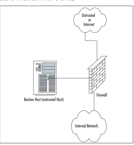
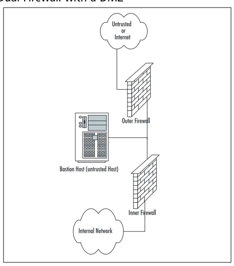
DMZ Concepts . . . .32
Traffic Flow Concepts . . . .37
Networks with and without DMZs . . . .41
Pros and Cons of DMZ Basic Designs . . . .42
DMZ Design Fundamentals . . . .44
Why Design Is So Important . . . .45
Designing End-to-End Security for Data Transmission between Hosts on the Network . . . . .46
Traffic Flow and Protocol Fundamentals . . . .46
Summary . . . .47
Solutions Fast Track . . . .47
Frequently Asked Questions . . . .49
Chapter 2 Dissecting the SonicWALL. . . 51
Introduction . . . .52
The SonicWALL Security Product Offerings . . . .53
Firewalls . . . .53
SSL VPN . . . .54
Content Security Manager . . . .55
The SonicWALL Firewall Core Technologies . . . .55
SonicOS . . . .55
Zones . . . .59
Interface Modes . . . .60
Access Rules . . . .60
VPN . . . .61
Deep Inspection . . . .61
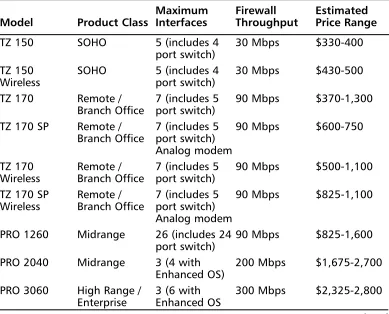
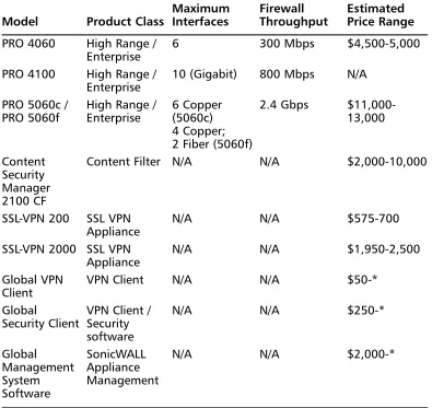
The SonicWALL Product Line . . . .64
Product Line . . . .65
SonicWALL VPN Clients . . . .66
Small Office/Home Office . . . .67
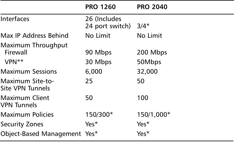
Midrange . . . .71
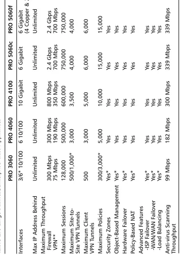
Enterprise Class . . . .73
Enterprise Management . . . .77
Summary . . . .79
Solutions Fast Track . . . .80
Frequently Asked Questions . . . .82
Chapter 3 Deploying SonicWALL Firewalls . . . 85
Introduction . . . .86
Managing the SonicWALL Firewall . . . .86
SonicWALL Management Options . . . .87
Serial Console . . . .87
WebUI . . . .88
The SonicWALL GMS . . . .89
Administrative Users . . . .90
The Local File System and the Configuration File . . . . .90
Using the Command-Line Interface . . . .91
Using the Web User Interface . . . .96
Securing the Management Interface . . . .97
Updating and Managing SonicOS . . . .103
System Recovery . . . .106
Zones, Interfaces, and VLANs . . . .108
Zones . . . .108
Interfaces . . . .110
Binding an Interface to a Zone . . . .111
VLANs . . . .112
Advanced Features . . . .113
Configuring the SonicWALL Firewall . . . .113
Other Methods for Configuring the WAN Interface . . .116
Configuring the DHCP Client . . . .117
Configuring PPPoE for the WAN interface . . . .117
Configuring PPTP . . . .118
Interface Speed Modes . . . .118
Configuring System Services . . . .119
Setting the Time . . . .120
DHCP Server . . . .120
IP Helper . . . .120
DNS . . . .121
Licenses . . . .121
Syslog . . . .123
Summary . . . .124
Solutions Fast Track . . . .125
Frequently Asked Questions . . . .126
Chapter 4 Policy Configuration . . . 127
Introduction . . . .128
Theory of Access Control . . . .128
Access Rule Components . . . .128
Zones . . . .129
Predefined Zones . . . .129
User-Defined Zones . . . .130
Creating Zones . . . .131
Interfaces . . . .133
Address Objects . . . .137
Address Groups . . . .137
Creating Address Objects and Address Groups . . . .138
Predefined Address Objects and Address Groups . . . .140
Service Objects and Service Groups . . . .141
NAT Policies . . . .145
SonicWALL Access Rules . . . .149
Access Rules—Part 1 . . . .150
Access Rule Views . . . .150
Creating Access Rules . . . .155
Editing, Deleting, Enabling, and Disabling Access Rules 156 Resetting the Rule Base for a Specific Zone . . . .156
Viewing Traffic Statistics for Specific Access Rules . . . .156
Advanced Rules Options . . . .157
BWM . . . .159
Default Access Rules . . . .162
Access Rules—Part 2 . . . .164
Getting Ready to Create Access Rules . . . .164
Access Rule Example 1— Firewall Management Rules . . . .164
Access Rule Example 2— Restricting Outbound Traffic . . . .167
Access Rule Example 3— Allowing Inbound SMTP Traffic and Web Traffic . . .171
Advanced Options for Firewalls . . . .176
Detection Prevention . . . .177
Dynamic Ports . . . .178
Source-Routed Packets . . . .178
Connections . . . .179
Access Rule Service Options . . . .179
TCP Settings . . . .179
TCP Traffic Statistics . . . .179
TCP Settings . . . .182
SYN Flood Protection . . . .184
SYN Flood Protection Overview . . . .186
Layer 3 SYN Flood Protection . . . .186
SYN Flood Protection Mode . . . .186
SYN Attack Threshold . . . .187
SYN-Proxy Options . . . .187
SYN Proxy Threshold . . . .188
Layer 2 Protection . . . .189
Multicast . . . .190
Summary . . . .191
Solutions Fast Track . . . .191
Frequently Asked Questions . . . .194
Chapter 5 User Authentication . . . 197
Introduction . . . .197
Types of Users . . . .198
Local Users . . . .198
Local Groups . . . .199
Guest Services . . . .200 Guest Accounts . . . .202 User Settings . . . .203 User Login Settings . . . .203 User Session Settings . . . .204 Other Global User Settings . . . .204 Acceptable Use Policy . . . .205 Authentication Methods . . . .205 Local Users . . . .205 RADIUS . . . .206 LDAP . . . .207 Summary . . . .210
Chapter 6 Routing . . . 211
Introduction . . . .212 Routing Information Protocol (RIP) . . . .212 Networking with RIP . . . .213 When to Use RIP . . . .216 RIP as It Applies to SonicWALL . . . .216 Open Shortest Path First (OSPF) . . . .217 Networking with OSPF . . . .217 How OSPF Works . . . .218 When to Use OSPF . . . .219 Basic OSPF Configuration on a SonicWALL . . . .219 Summary . . . .220 Solutions Fast Track . . . .221
Chapter 7 Address Translation. . . 223
NAT Policy Basics . . . .235 Many-to-One NAT . . . .237 Many-to-Many NAT . . . .238 One-to-One NAT . . . .239 Reflexive Policies . . . .240 One-to-One NAT with Port Translation . . . .241 One-to-Many . . . .241 Summary . . . .243 Solutions Fast Track . . . .243 Frequently Asked Questions . . . .245
Chapter 8 Transparent Mode . . . 247
Introduction . . . .248 Interface Settings . . . .248 Permanently Assigned Interfaces . . . .249 Understanding How Transparent Mode Works . . . .250 Configuring a Device to Use Transparent Mode . . . .251 Transparent Mode Deployment Options . . . .253 Summary . . . .255 Solutions Fast Track . . . .255 Frequently Asked Questions . . . .257
Chapter 9 Attack Detection and Defense . . . 259
Creating and Configuring User/
Group Exclusion and Inclusion Groups . . . .277 Configuring IP Address Range
Inclusion and Exclusion Lists . . . .282 SonicWALL Content Filtering . . . .284 Configuring SonicWALL CFS . . . .290 CFS Tab . . . .291 Settings . . . .291 Policy Tab . . . .293 Custom List Tab . . . .297 Consent Tab . . . .298 Creating Custom CFS Policies . . . .300 Antivirus Services . . . .302 Network Antivirus . . . .302 SonicWALL Gateway Antivirus . . . .309 SonicWALL Anti-Spyware . . . .310 Configuring Anti-Spyware . . . .311 E-Mail Filter . . . .316 RBL Filter . . . .319 Summary . . . .322 Solutions Fast Track . . . .322 Frequently Asked Questions . . . .324
Chapter 10 Creating VPNs with SonicWALL . . . 325
VPNs in SonicWALL Appliances . . . .336 Site-to-Site VPNs . . . .336 Creating a Site-to-Site VPN . . . .338 Corporate Office—New York . . . .339 Branch Office—Phoenix . . . .344 SonicWALL GroupVPN . . . .346 Deploying GroupVPN . . . .347 L2TP VPNs . . . .355 Gateway Redundancy . . . .359 Summary . . . .360 Solutions Fast Track . . . .361 Links . . . .364 Frequently Asked Questions . . . .364
Chapter 11 High Availability . . . 367
Introduction . . . .368 The Need for HA . . . .368 Configuring Hardware Failover in SonicWALL Firewalls . .369 Hardware and Software . . . .369 Network Requirements . . . .370 Licensing and Security Services . . . .370 Loose Ends: Configuring Monitoring Addresses and
Management IPs . . . .371 Configuring Monitoring Links . . . .372 Tips,Tricks,Traps, and Tuning . . . .373 Failover Function Test . . . .373 Cabling an HA Pair . . . .373 Adding a SonicWALL Unit to a HF Configuration . . . .375 Determining When to Failover . . . .376 How HF “Fails Over” . . . .376 Tuning . . . .377 Summary . . . .379 Solutions Fast Track . . . .379
Chapter 12 Troubleshooting the SonicWALL . . . 381
Chapter 13 Enterprise SonicWALL Management. . . 423
SonicWALL Management and Reporting . . . .424 SonicWALL ViewPoint . . . .424 Installation . . . .424 Configuring ViewPoint . . . .430 SonicWALL Global Management
System Installation and Configuration . . . .432 Hardware Requirements . . . .433 SQL Server Setup . . . .434 Java Database Connectivity ( JDBC) Driver . . . .445 Stand-Alone SGMS Installation . . . .445 Stand-Alone Installation . . . .446 Distributed Reporting . . . .454 Registering SGMS . . . .456 Configuring GMS . . . .457 Policies Panel . . . .457 Reporting Panel . . . .457 Console Panel . . . .458 Monitoring Panel . . . .459 Introduction to Views . . . .460 Adding SonicWALL Appliances to SGMS . . . .461 User Settings . . . .463 Log . . . .465 Tasks . . . .466 Management . . . .467 GMS Settings . . . .467 Alert Settings . . . .468 Users . . . .469 Custom Groups . . . .469 Summary . . . .484 Solutions Fast Track . . . .484 Frequently Asked Questions . . . .486
Networking,
Security, and
the Firewall
Solutions in this chapter:
■ Understanding Networking
■ Understanding Security Basics
■ Understanding Firewall Basics
Chapter 1
1
Summary
Solutions Fast Track
Introduction
Every enterprise requires at least one firewall to provide the backbone for its net-work security architecture. Firewalls are the core component of your netnet-work’s secu-rity.The risks today have greatly increased, so the call for a stronger breed of firewall has been made. In the past, simple packet-filtering firewalls allowing access to your internal resources have helped to mitigate your network’s risk.The next develop-ment was stateful inspection allowing you to monitor network sessions instead of single packets.Today’s risks are far greater and require a new generation of devices to help secure our networks’ borders from the more sophisticated attacks.
Firewalls police your network traffic. A firewall is a specialized device that allows or denies traffic based upon administratively defined policies.They contain technolo-gies to inspect your network’s traffic.This technology is not something that is exclu-sive to firewalls, but firewalls are designed specifically for inspecting traffic and therefore do it better then any other type of device. Any network can have millions of packets transverse it in a short period of time. It is impossible for a human to directly interact with the network. Even if you were to use a tool to look at the traffic directly it would be impossible for you to decide which traffic is good and which is bad.The need for a specialized device to enforce traffic restrictions has grown over the years. Because security is of such high importance, a specialized device was required to ensure the security of network traffic.
SonicWALL firewall appliances have answered this call for a secure enterprise. The SonicWALL firewall product line has complete offerings from the home office to the enterprise networks. In this chapter we will review networking basics.
Security requires a strong basic knowledge of networking protocols. In our first sec-tion, “Understanding Networking,” we will look at networking from a top-down approach.This section starts with the basic ideas of networking models and then works into full networking communications. We will also discuss the components and prerequisites of IP addresses and how they are divided up to make networks.
Understanding Networking
To understand networking is to understand the language of firewalls. A firewall is used to segment resources and limit access between networks. Before we can really focus on what a firewall does for us, we need to understand how networking works. Today in most environments and on the Internet, the protocol suite TCP/IP
(Transmission Control Protocol/Internet Protocol) is used to transport data from here to there. We will begin this chapter by looking at networking as a whole with a focus on the Open System Interconnection (OSI) model.
The OSI Model
The OSI model was originally developed as a framework to build networking pro-tocols on. During the time when then Internet was being developed, a protocol suite named TCP/IP was developed.TCP/IP was found to meet the requirements of the Internet’s precursor, ARPANET. At this point,TCP/IP was already integrated into UNIX and was quickly adopted by the academic community as well. With the advent of the Internet and its widespread usage,TCP/IP has become the de facto standard protocol suite of internetworking today.
The OSI model consists of seven distinct layers.These layers each contain the fundamental ideas of networking. In Figure 1.1 we can see the way that the seven layers stack on top of each other.The idea is that each upper layer is encapsulated inside of each lower layer. So ultimately, any data communications are transformed into the electrical impulses that pass over the cables or through the air that surrounds us. Understanding the OSI model is understanding the core of networking. In many places throughout this book, the OSI model is used to create a visual representation of networking.
The reality, however, is that the OSI model is just a reference model that proto-cols are based upon.The next section, called “Moving Data Along With TCP/IP,” demonstrates how some of the layers blur together. All in all, the OSI model is a great tool to help anyone understand networking and perform troubleshooting. Over the years, the OSI model has served as a reference for all protocols that have been developed. Almost every book, manual, white paper, or Web site that talks about net-working protocols references the OSI model. It is important to have a baseline when discussing every topic.
have common components.They both have wheels, doors, brakes, and engines.This is much like the different components of a network protocol, which is essentially a vehicle for data. Networking protocols have components to help get the data from here to there, like wheels.They have components to control the flow of data, like brakes.These are all requirements of any protocol. Using and understanding the OSI model makes protocol usage and design easier. Whether TCP/IP or IPX/SPX, most protocols are built around the same framework (model).
Figure 1.1 The Seven-Layer OSI Model
7. Application Layer 6. Presentation Layer 5. Session Layer 4.Transport Layer 3. Network Layer 2. Data Link Layer 1. Physical Layer
Layer 7:The Application Layer
The application layer contains application data.This is the layer at which applications communicate to one another.The reason for all of the other layers is essentially to transport the messages contained at the application layer. When communicating with each other, the applications use their own language, as specified by that application’s standard. A perfect example of an application protocol is Hypertext Transfer Protocol (HTTP). HTTP is used to send and receive Web content. When HTTP is used to pass data from server to client, it employs something called HTTP headers. HTTP headers are effectively the language of HTTP. When the client wants to request data from a server, it issues a request to get the content from the server.The server then responds with is headers and the data that was requested. All of this is an example of application layer communications. Other examples of application layer protocols are File Transfer Protocol (FTP), Domain Name Service (DNS),Telnet, and Secure Shell (SSH).
Layer 6:The Presentation Layer
computer. However, each image file must be the proper specified file format.This way, the application that reads the image file understands the type of data and the format that is contained in it. A JPEG file and a PNG file may contain the same image, but each uses a separate format. A JPEG file cannot be interpreted as a PNG and vice versa. Additionally, file-level encryption occurs at the presentation layer.
Layer 5:The Session Layer
The session layer controls sessions between two systems. It is important to have ses-sions, as it is the core of any communications for networking. If you did not have sessions, all communications would run together without any true idea of what is happening throughout the communication. As you will see below,TCP/IP has no session layer, really. In TCP/IP the session layer blends together with the transport layer. Other protocols such as NetBIOS, used on Microsoft networks, use the session layer for reliable communications.
Layer 4:The Transport Layer
The transport layer provides a total end-to-end solution for reliable communications. This layer provides the mechanisms for reliable communications.TCP/IP relies on the transport layer to effectively control communications between two hosts. When an IP communication session must begin or end, the transport layer is used to build this connection.The elements of the transport layer and how it functions within TCP/IP are discussed in more detail later in the chapter.The transport layer is the layer at which TCP/IP ports listen.
Layer 3:The Network Layer
When packets have to get between two stations on a network, the network layer is responsible for the transportation of these packets.The network layer determines the path and the direction on the network in order to allow communications between two stations.The IP portion of TCP/IP rests in this part of the OSI model. IP is discussed in detail in the following section.
Layer 2:The Data Link Layer
Control (SDLC), and X.25. Protocols such as Address Resolution Protocol (ARP) function at the Data Link Layer.
Layer 1:The Physical Layer
The last but most important layer of the OSI model is the physical layer.The phys-ical layer consists of the objects that connect stations together physphys-ically.This layer is responsible for taking the bits and bytes of the higher layers and passing them along the specified medium.There are many examples of the physical layer that you should already have heard of, such as Cat5 cable,T1, and wireless.
Moving Data Along with TCP/IP
On the Internet and most networks,TCP/IP is the most commonly used protocol for passing network data. At the time of its development,TCP/IP used a very
advanced design. Decades later,TCP/IP continues to meet the needs of the Internet. The most commonly used version of IP used today is version 4, the version covered in this book.The next generation IP, version 6, is starting to be used much more throughout the world. Many vendors, including Juniper Networks, Cisco, Microsoft, and Apple, are developing software that supports the new IP version 6 standard.
Over the course of this section, we will cover how systems use TCP/IP to interact, and we will review the IP and how its protocol suite compares to the OSI model. We will also discuss how IP packets are used to transmit data across networks, and we will examine the transport layer protocols TCP and User Datagram Protocol (UDP) and how they are used to control data communications in conjunction with IP. Finally, we will wrap up the discussion of TCP/IP with information about the data link layer.
Understanding IP
The Internet Protocol is used to get data from one system to another.The IP sits on the third layer of the OSI model, the network layer. When you need to send data across a network, that data is encapsulated in a packet. A packet is simply a segment of data that is sent across the network. In TCP/IP however, there are not seven true layers as there are in the OSI model (see Figure 1.2 for a comparison of TCP/IP and OSI model layers).
Figure 1.2 OSI Model Layers versus TCP/IP Layers
OSI Model TCP/IP Model
7. Application Layer 5. Application Layer 6. Presentation Layer
5. Session Layer 4. Transport Layer 4. Transport Layer
3. Network Layer 3. Network Layer
2. Data Link Layer 2. Data Link Layer 1. Physical Layer 1. Physical Layer
Let’s look at an example of IP connectivity. We will be referencing the TCP/IP model, as it will be easier to understand for this example. Remember that the TCP/IP model is a condensed version of the OSI model. Use Figure 1.2 to refer-ence the steps of the OSI model on the left to the TCP/IP model on the right.You can use your Web browser to connect to www.syngress.com and view the series of events that occur during a network (in this case, the Internet) connection. We will look at the course of action that happens for the first packet that is created for this connection.
First, enter the address in the Web browser and then press Enter.The browser will make a request to get the data from the server.This request is then given to the transport layer where it initiates a session to the remote machine.To get to the remote machine, the transport layer sends its data to the network layer and creates a packet.The data link layer’s job is to get the packet across the local network. At this point, the packet is called a frame. At each junction point between systems and routing devices, the data link layer makes sure that the frame is properly transmitted. The physical layer is used during the entire connection to convert the raw data into electrical or optical impulses.
When the end station receives the packet, that station will convert the packet back to the application layer.The electrical impulses are changed at the physical layer into the frame.The frame is then unencapsulated and converted to individual
fol-lowing sections, we will expand on this example and show you what happens behind the scenes when two stations have a network conversation.
The following list provides a rundown of the phases of connectivity:
1. The URL www.syngress.com is entered into the browser.
2. The user presses Enter and forces the browser to connect to the Web site.
3. The browser makes a request to the server.
4. The browser request is handed to the transport layer.
5. The transport layer initiates a session to the remote server.
6. The transport layer passes its request to the network layer.
7. The network layer creates a packet to send to the remote server.
8. The data link layer takes the packet and turns it into a frame.
9. The frame is passed over the local network by the physical layer.
10. The physical layer takes the frame and converts it into electrical or optical impulses.
11. These impulses pass between devices.
12. At each junction point or router, the packet is transformed to the data link layer.
13. The packet is taken from the data link layer to the network layer.
14. The router looks at the packet and determines the destination host.
15. The router forwards the packet to the next and all subsequent routers until it reaches the remote system.
16. The end station receives the packet and converts it back through the layers to the application layer.
17. The remote system responds to the client system.
IP Packets
Figure 1.3 IP Packet Header Contents
Header Type of
Version Length Service Length
Identification Flags Fragment Offset
TTL Protocol Header Checksum
Source IP Address Destination IP Address
Options Data
So the question remains, “how do IP packets actually get from system to system?” Let’s reference our previous example of browsing to www.syngress.com. When the IP packet is formed, it includes the source IP address (the IP address of the client system making the request).This is like the return address on an envelope it tells the recipient where to send return mail to.The packet also receives the desti-nation address of the Web server being contacted.There are other parts that are set in the IP header, but are not germane to this discussion. After the packet is created, it is sent to the originating system’s routing table.The routing table is referenced and then the operating system determines which path to send this packet to. In routing, each system that receives the packet determines the next location or hop to send the packet to. So when sending information or requests across the Internet, there may be 15 hops or routers to go through before you get to the final system you are trying to connect to. Simply stated, a router is a system whose primary function is to route traffic from one location to another. As each router receives a packet it determines the next best location to send it to.
This, of course, is very simplified, as there are millions of routers on the Internet. Once the destination system receives the IP packet, it formulates a response.This is then sent back to the client system.The IP header contains the source address of the server that received the first packet and then the destination address of the initiating client machine.This is the fundamental basis of IP communications.
Table 1.1The IP Protocol Suite
Protocol Number Name Protocol
1 ICMP Internet Control Message Protocol
4 IP IP to IP Encapsulation
6 TCP Transmission Control Protocol
17 UDP User Datagram Protocol
50 ESP Encapsulating Security Payload
51 AH Authentication Header
One of the most important protocols in the IP protocol suite is the Internet Control Messaging Protocol (ICMP). ICMP is used as a messaging protocol to give information to the source or destination machine that is engaging in IP communica-tions.Table 1.2 lists all of the commonly used ICMP types and codes.To give an example of ICMP, let’s look at the common application ping. Ping is an application that is on pretty much any operating system, including SonicOS. It is used to test if a host is responsive from a network perspective. When you ping a host, an IP packet is generated that has the source IP address of the requesting system and the destination IP address of the system you are trying to contact.This packet then has an ICMP type of eight and a code of zero.The destination system then would receive the packet and recognize that the IP packet is echo or echo request packet. It then creates an ICMP packet that is a type zero code zero.This is an echo reply packet, acknowledging the original request.
Table 1.2 ICMP Types and Codes
Type Name
0 Echo Reply
Codes Name
0 No Code
Type Name
3 Destination Unreachable
Codes Name
0 Network Unreachable
1 Host Unreachable
2 Protocol Unreachable
3 Port Unreachable
What Does an IP Address Look Like?
IP addresses are 32 bits in length.They consist of four eight-bit numbers. An
Table 1.3 IP Address Ranges by Class
Class Address Range
A 0.0.0.0 to 127.255.255.255
B 128.0.0.0 to 191.255.255.255
C 192.0.0.0 to 223.255.255.255
D 224.0.0.0 to 239.255.255.255
E 240.0.0.0 to 255.255.255.255
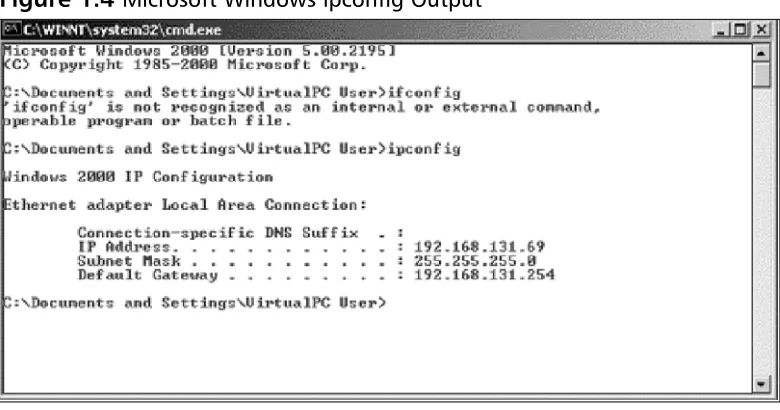
You can also use your own local computer to look at your IP address. We will use both a Windows system and a UNIX-based system as an example. Open up a DOS window on your Microsoft Windows system, then enter the command
[image:40.504.49.439.287.492.2]ipconfig. An example of this is shown in Figure 1.4.You can also do the same thing on a UNIX-based system by using the command ifconfig. An example of this is shown in Figure 1.5.
Figure 1.5 UNIX ifconfig Output
IP Address Allocation
When you are creating a network, deciding on IP address allocation is very impor-tant. But with billions of options, how does one decide? The Internet Assigned Numbers Authority, or IANA, is responsible for allocating IP addresses.They deter-mine which organizations get which IP address ranges.They are also responsible for conserving IP addresses and planning for future uses for IP addresses. Does this mean that you need to contact them to get IP addresses? Unless you are starting your own Internet Service Provider (ISP) the size of Qwest or SBC, you do not need to con-tact them.Your ISP will always assign any Internet or public IP addresses, and for private IP address networks you would use the IP addresses that are specified in RFC 1918. See Table 1.4 for a list of the private IP address ranges. A non-Internet routable IP is an IP address that is not routed on the Internet. If a packet was to leave your network with a source or destination IP address in one of these ranges, it would not get very far.
Table 1.4 RFC 1918 IP Address Ranges
Class Address Range
A 10.0.0.0 to 10.255.255.255
B 172.16.0.0 to 172.31.255.255
C 192.168.0.0 to 192.168.255.255
NAT and Private IP Addresses
into a public IP address. When the SonicWALL firewall receives the return packet, it translates the new destination address to the private IP address.There are two types of NAT: NAT source, and NAT destination.
TCP Communications
The Transmission Control Protocol is used to control the creation and form of data transfer connections.TCP is one of two transport layer protocols that are used as part of the TCP/IP protocol suite.TCP is designed to provide many functions mostly based on reliability.TCP is used for applications that require reliability over speed. When talking about speed at this level, we are talking about calculations of millisec-onds or less.TCP functions as a stateful protocol.This means that during the com-munications, the connection has specific states in which it functions.There is a clear beginning, middle, and end of a TCP connection.
When a TCP session begins, it goes through a three-way handshaking process. Inside of a TCP header, options (called flags) are set.These flags identify the type of TCP message that has been sent.The three-way handshake process is shown in Figure 1.6. Let’s continue to use our earlier example of using your Web browser to access www.syngress.com. When your web browser attempts to make its connection to the Web server, it attempts to open a connection to TCP port 80. A port is a spe-cific communications channel spespe-cific to a particular application.TCP port 80 is the default port for HTTP.
The first packet that is sent to the Web server is a SYN packet. A SYN packet is used to synchronize a connection between two hosts.This packet is also sent with a sequence number that is used to identify the packet inside of this connection.This sequence number is to be used for the initiating systems packets. Next, the Web server receives the packet acknowledges it.To do this, the server creates and sends a packet with the TCP flags SYN and ACK. A packet that has the ACK (or acknowledgement) flag set is sending a message to the other system that says,“I have received your packet”. A sequence number is also given to this packet that is independent of the sequence number that is associated with the initiating system’s sequence number.The system that initiated the connection now sends an ACK packet to acknowledge the connection.The ACK packet has a sequence number that is incremented, as it is the second packet that has been sent from this system.The TCP session has now been cre-ated and the requested data from the Web server can begin to pass to the client.
example, a client receives packets with sequence numbers 6, 7, 8, and 10, but never receives packet 9, the client will request that packet nine be resent from the server. On the client, all of the packets would be reordered before passing the data back to the application. When the connection is completed, the server system would send a packet with the FIN flag.This indicates that the connection is finished.The client would then send an ACK packet back to the server acknowledging that the conver-sation has completed.
Figure 1.6 TCP Session Initialization
UDP Communications
The User Datagram Protocol is a connectionless protocol that is designed to stream data. When a UDP connection occurs, there is no beginning, middle, or end to the conversation. Data simply begins to flow between the two systems. UDP is a very simple protocol and is used when speed is an issue. UDP packet receipt is not veri-fied. An example of a use of UDP is DNS queries. When you attempt to use your Web browser to access www.syngress.com, it must first resolve the name to an IP address.This would require a DNS query.The query is sent over a single UDP packet.The DNS server would then respond by telling the originating system the IP address of the Web server. Because the UDP response is faster than setting up a TCP session, UDP makes sense in these situations. Another example of using UDP is voice over IP (VoIP).The downfall, of course, is the lack of reliability, so you may have to employ other methods to guarantee delivery.
`
Example of a three-way handshake for a TCP session initialization
Client Server
SYN ACK
What Is a Port?
Both TCP and UDP support the use of ports. But what exactly is a port? Let’s look at an example that can help further explain this. When you turn on your television, you get a picture and sound. Every time you change the channel, each new channel contains different content.This is much like a TCP or UDP port. Each port contains a specific type of content or application. When you tune to that port, you can access those specific resources.Theoretically, you can put any application on any port, but by specifying specific ports for specific applications, you can always be assured of the type of content you will find on a specific port.
This is why a specification of well-known ports has been established.Table 1.5 lists well-known TCP and UDP ports. Using our earlier television example, you can see that this is much like a channel lineup. If television programming could appear on any television channel, there would be a lot of confusion about which program-ming you were watching. When you use your television, the service provider gives you a channel lineup.This lineup is specified so that you know which channel is which. Most Web servers serve data over port 80. Again, they can serve the data over any port, but it would be very hard to get the content if you did not know which port to use.
Table 1.5 Well-Known TCP and UDP Ports
Well-Known TCP Ports Well-Known UDP Ports
FTP 21 DNS 53
SSH 22 DHCP-Relay 67
Telnet 23 TFTP 69
SMTP 25 NTP 123
HTTP 80 IKE 500
IMAP 143 Syslog 514
HTTPS 443 H.323 1719
Data Link Layer Communication
time of this writing the main layer two protocol that is used by SonicWALL firewalls is Ethernet.
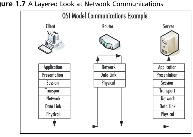
Ethernet is the most commonly used medium today in corporate networks. It is inexpensive to use, easy to set up, and can operate at incredible speeds.The data link layer is used to communicate across the local medium. Figure 1.7 shows the break-down of the use of layers and where they take place during system-to-system com-munication. When systems need to talk over Ethernet, they cannot use IP addresses, because Ethernet is at a lower level and it is used to move IP between layer three devices. So each device on an Ethernet segment uses a Media Access Control
[image:45.504.81.398.244.470.2](MAC) address. When a station needs to have a conversation, the source and destina-tion systems use their MAC addresses to identify each other. Each manufacturer is assigned a range to use when creating Ethernet adapters.Then each individual adapter is given a unique number to create the MAC address.
Figure 1.7 A Layered Look at Network Communications
Because systems communicate via IP, but need to talk over Ethernet (which requires the use of MAC addresses), there has to be a way to resolve an IP to a MAC address.The method used is called the Address Resolution Protocol, or ARP. For example, if system A, which has an IP address of 192.168.1.10, wanted to view the Web pages on system B, which has an IP address of 192.168.1.25, before the com-munications can begin, system A must learn the MAC address of system B. System A broadcasts a request over the local broadcast domain asking who has the IP address 192.168.1.25. A broadcast is a communication that is sent out to every system that is
`
OSI Model Communications Example
Client Router Server
within a broadcast area. All of the systems in the broadcast area get this request and the system with the requested IP address responds with a unicast message that speci-fies it has the IP address of 192.168.1.25 and also provides its MAC address.
Because almost everyone uses a computer today, a typical company can contain at least twenty computers or more.There are many ways to connect computers together. If you have just two systems, you can connect them with just a crossover Ethernet cable. A crossover cable is an Ethernet cable that allows two systems to directly connect to each other. If you have two to four computers, you could use a hub or bridge. If you have four or more computers, you will likely want to use a switch. A hub or bridge is a device that connects several systems together. When two systems want to access the Ethernet media to transfer data, their communications take up the use of the media while they are talking. If a third system wants to talk over the network, it simply starts talking and the data frames will collide with those of the already ongoing communication. An Ethernet segment where the media is shared between is called a collision domain. Switches, however, do not have this problem. When two systems begin a network conversation on a network with a switch, the packets are isolated and the switch prevents packets from colliding. If a system was to broadcast, however, the broadcast would be sent to every system con-nected to the switch. When the switch sends the data between two hosts, it sends it such a way that other network conversations are not interrupted.
Understanding Security Basics
The Need for Security
Enterprise security is the hottest technology trend today. Every aspect of a com-pany’s data infrastructure has the need for security. With ever–growing, ever-evolving networks in every organization, managing security has become harder. For many organizations, the operating budget for security is less than one percent of there total company budget. When it comes down to purchasing security products, firewalls are the core product used to secure the enterprise network. However, firewalls should by no means be the only method used to secure your network, but used effectively, they can mitigate the risks of network security breaches and data loss. With integrated technologies such as anti-virus, deep packet inspection, Uniform Resource Locator (URL) filtering, and virtual private networks (VPNs), the firewall can provide a host of security applications all in one system. As the old saying goes, however, you should never put all of your eggs in one basket.
Introducing Common Security Standards
Security and network professionals use a number of currently accepted procedures and standards to conduct business and ensure that we are following the accepted practices for security and access. Although we have a responsibility as network and systems administrators to try to attain perfection in the availability and integrity of our data, we also have constraints placed on us in accomplishing those tasks.These constraints include budgets, physical plant capability, and training of users and techni-cians to maintain the security and integrity of the data.These constraints do not relieve us of our responsibility of maintaining the data safely and securely.To that end, we currently employ some accepted standards for security that help us perform our tasks to the best possible level. In this section, we remind you of the common security standards and briefly discuss them:
■ Authentication, authorization, and auditing (AAA) AAA use is
required in security operations for creating and maintaining the method of authenticating users and processes, and validating their credentials prior to allowing access to resources. It is also the method we use to grant access or deny access to the resource. Auditing of activity is a crucial part of this function.
■ Confidentiality, integrity, and availability (CIA) CIA is the originally
processes have expanded to include a more comprehensive guideline that also includes the process of defining risk and use of risk management tools to provide a more complete method of protection.
■ Least privilege This concept is used by the security planners and teams to
define the levels of access to resources and the network that should be allowed. From a security standpoint, it is always preferable to be too restric-tive with the capability to relax the access levels than to be too loose and have a breach occur.
Remember, too, that the security process involves a three-tiered model for secu-rity protection:
■ Computer security, including the use of risk assessment, the expanded
CIA goals, and enterprise planning that extends throughout the entire enterprise, rather than to just a portion of it.
■ Physical security, in which we must build and include physical access
sys-tems and coordinate them with our network access syssys-tems.
■ Trusted users, who become an important cog in maintaining the
integrity of our security efforts.
Common Information Security Concepts
A generic dictionary definition of security (taken from the American Heritage
Dictionary) is, “freedom from risk or danger; safety.”This definition is perhaps a little misleading when it comes to computer and networking security, because it implies a degree of protection that is inherently impossible to achieve in the modern connec-tivity-oriented computing environment.
Defining Information Security
Over the last couple of decades, many companies began to realize that their most valuable assets were not only their buildings or factories, but also the intellectual property and other information that flowed internally as well as outwardly to sup-pliers and customers. Company managers, used to dealing with risk in their business activities, started to think about what might happen if their key business information fell into the wrong hands, perhaps a competitor’s.
For a while, this risk was not too large, due to how and where that information was stored.Closed systemswas the operative phrase. Key business information, for the most part, was stored on servers accessed via terminals or terminal emulators and had few interconnections with other systems. Any interconnections tended to be over private leased lines to a select few locations, either internal to the company or to a trusted business partner.
However, over the last five to seven years, the Internet has changed how busi-nesses operate, and there has been a huge acceleration in the interconnectedness of organizations, systems, and networks. Entire corporate networks have access to the Internet, often at multiple points.This proliferation has created risks to sensitive information and business-critical systems where they had barely existed before.The importance of information security in the business environment has now been underscored, as has the need for skilled, dedicated practitioners of this specialty.
We have traditionally thought of security as consisting of people, sometimes with guns, watching over and guarding tangible assets such as a stack of money or a research lab. Maybe they sat at a desk and watched via closed-circuit cameras installed around the property.These people usually had minimal training and some-times did not understand much about what they were guarding or why it was important. However, they did their jobs (and continue to do so) according to estab-lished processes, such as walking around the facility on a regular basis and looking for suspicious activity or people who do not appear to belong there.
Information security moves that model into the intangible realm. Fundamentally, information security involves making sure that only authorized people (and systems) have access to information. Information security professionals sometimes have dif-ferent views on the role and definition of information security
The three primary areas of concern in information security have traditionally been defined as follows:
■ Confidentiality Ensuring that only authorized parties have access to
■ Integrity Ensuring that information is not modified by unauthorized par-ties (or even improperly modified by authorized ones!) and that it can be relied on. Checksums and hashes are used to validate data integrity, as are transaction-logging systems.
■ Availability Ensuring that information is accessible when it is needed. In
addition to simple backups of data, availability includes ensuring that sys-tems remain accessible in the event of a denial of service (DoS) attack. Availability also means that critical data should be protected from erasure— for example, preventing the wipeout of data on your company’s external Web site.
Often referred to simply by the acronym CIA, these three areas serve well as a security foundation.To fully scope the role of information security, however, we also need to add a few more areas of concern to the list. Some security practitioners include the following within the three areas described above, but by getting more granular, we can get a better sense of the challenges that must be addressed:
■ Authentication Ensuring that users are, in fact, who they say they are.
Passwords, of course, are the longstanding way to authenticate users, but other methods such as cryptographic tokens and biometrics are also used.
■ Authorization/access control Ensuring that a user, once authenticated,
is only able to access information to which he or she has been granted per-mission by the owner of the information.This can be accomplished at the operating system level using file system access controls or at the network level using access controls on routers or firewalls.
■ Auditability Ensuring that activity and transactions on a system or
net-work can be monitored and logged in order to maintain system availability and detect unauthorized use.This process can take various forms: logging by the operating system, logging by a network device such as a router or firewall, or logging by an intrusion detection system (IDS) or packet-cap-ture device.
■ Nonrepudiation Ensuring that a person initiating a transaction is
You can say that your information is secure when all seven of these areas have been adequately addressed.The definition of adequately depends, however, on how much risk exists in each area. Some areas may present greater risk in a particular environment than in others.
Insecurity and the Internet
The federation of networks that became the Internet consisted of a relatively small community of users by the 1980s, primarily in the research and academic communi-ties. Because it was rather difficult to get access to these systems and the user com-munities were rather closely knit, security was not much of a concern in this
environment.The main objective of connecting these various networks together was to share information, not keep it locked away.Technologies such as the UNIX operating system and the TCP/IP networking protocols that were designed for this environment reflected this lack of security concern. Security was simply viewed as unnecessary.
By the early 1990s, however, commercial interest in the Internet grew.These commercial interests had very different perspectives on security, ones often in oppo-sition to those of academia. Commercial information had value, and access to it had to be limited to specifically authorized people. UNIX,TCP/IP, and connections to the Internet became avenues of attack and did not have much capability to imple-ment and enforce confidentiality, integrity, and availability. As the Internet grew in commercial importance, with numerous companies connecting to it and even building entire business models around it, the need for increased security became quite acute. Connected organizations now faced threats that they had never had to consider before.
When the corporate computing environment was a closed and limited-access system, threats mostly came from inside the organizations.These internal threatscame from disgruntled employees with privileged access who could cause a lot of damage. Attacks from the outside were not much of an issue since there were typically only a few, if any, private connections to trusted entities. Potential attackers were few in number, since the combination of necessary skills and malicious intent were not at all widespread.
Threats can be classified as structured or unstructured.Unstructured threats are from people with low skill and perseverance.These usually come from people called
script kiddies—attackers who have little to no programming skill and very little system knowledge. Script kiddies tend to conduct attacks just for bragging rights among their groups, which are often linked only by an Internet Relay Chat (IRC) channel. They obtain attack tools that have been built by others with more skill and use them, often indiscriminately, to attempt to exploit vulnerability in their target. If their attack fails, they will likely go elsewhere and keep trying. Additional risk comes from the fact that they often use these tools with little to no knowledge of the target environment, so attacks can wind up causing unintended results. Unstructured threats can cause significant damage or disruption, despite the attacker’s lack of sophistication.These attacks are usually detectable with current security tools.
Structured attacksare more worrisome because they are conducted by hackers with significant skill. If the existing tools do not work for them, they are likely to modify them or write their own.They are able to discover new vulnerabilities in systems by executing complex actions that the system designers did not protect against. Structured attackers often use so-called zero-day exploits, which are exploits that target vulnerabilities that the system vendor has not yet issued a patch for or does not even know about. Structured attacks often have stronger motivations behind them than simple mischief.These motivations or goals can include theft of source code, theft of credit card numbers for resale or fraud, retribution, or destruc-tion or disrupdestruc-tion of a competitor. A structured attack might be neither blocked by traditional methods such as firewall rules nor detected by an IDS. It could even use non-computer methods such as social engineering.
N
OTESocial engineering, also known as people hacking, is a means of