Article
Performance Evaluation of Four-Sided Square Wind
Catchers with Different Geometries by Numerical
Method
Maryam Hossein Ghadiri
1,a, Nik Lukman Nik Ibrahim
1,b, and Mohd Farid Mohamed
2,c1, 2 Department of Architecture, Universiti Kebangsaan Malaysia (UKM), Malaysia
E-mail: a[email protected] (Corresponding author), bn.lukman @email.com,
Abstract. The extensive enhance of using air conditioning to cool and ventilate buildings in hot - arid climate regions have turned into an actual crisis since these systems consume high load of electricity. Recently, green ventilation features such as wind catchers have been utilized as a solution in order to improve indoor air quality and decrease energy consumption. The most common ventilation device in hot and hot-humid areas of Iran was wind catcher or “Badgir”. This study is an outline of the results of a research on the wind catcher element in the traditional architecture of Iran. An appraisal of the wind towers' individuality with prominence on their morphology is presented and classification of the wind towers based on their physical characteristic and parameters are thus proposed. This paper also presents a limited wind driven simulation results which shows the impact of different square wind catcher’s plan geometry on the indoor ventilation rate. The simulations accomplished using computational fluid dynamics (CFD), reveal the effect of four different square wind catchers on the indoor ventilation rate.
Keywords: Wind catcher, natural ventilation System, wind catcher’s blade, Fluent software.
ENGINEERING JOURNAL Volume 17 Issue 4 Received 31 October 2012
1.
Introduction
Wind tower is one of the vernacular elements which is widely used in hot, hot dry and hot humid climates especially in countries like Iran [1]. They are tall towers on the building’s roof tops with several vents to capture wind for cooling the interior spaces [2]. This is one of the most beautiful connections between the architectural design and natural environment for conserving energy on the basis of sustainability principle. Wind catcher openings are usually positioned facing desired wind directions [3]. Wind catcher functions based on pressure difference between leeward and windward which is positive in inlet opening and negative in outlet vent. Venturi effect causes air to come down through the wind catcher channel at a higher velocity and lower pressure [3]. The desert areas experience cool nights and hot days and the temperature difference between night and day is high. Mud brick partitions are elements in wind tower which divide it into several shafts having a significant role on the performance of the wind catcher [4]. These partitions form a plane grid of vents ending to a heavy masonry roof on top of the tower. There are two kinds of partitions including main partition and secondary partition. Main partitions are long walls which are started between 1.5-2.5 m above the ground floor level [5]. These partitions form the cross section of the tower. They are varying in different towers based on the position of them. The most commons are in the forms of I, H and diagonal [6]. Secondary partitions remain as wide as the external wall, about 20-25 cm [7]. A shaft can be subdivided by a number of additional partitions performing either structural or thermal role. According to fluid dynamics and Bernoulli's principle for an inviscid flow, an increase in the speed of the fluid occurs, when the air passes through narrow sections, air velocity rate increases[8]. These partitions have two main roles to increase the air flow rate and to increase air contact. So warm air losses heat when it meets the partitions in inlet opening which were cooled last night. During this mass transfer the material of partitions which is mud brick has significant role. It has high capacity of heat storage and gives back stored heat during the night and are also good in absorbing heat. Thus wind with less heat will enter the space. Therefore, during the night when the outdoor temperature is low the walls temperature falls down and helps to cool the interior space during the next day [7]. Wind catchers operate well when the wind velocity is more than 3 m/s [9]. When the wind velocity is less than 3 m/s, the heat released by the wind catcher heats up the air inside it and drives the heat upward and outside the building [10].
2.
Previous Works
the wind speed is lower than 3 m/s. The performance of a cooling tower was studied for different climatic regions of Jordan, such as the desert areas where air conditioning is needed most [18]. It was found that under those climates, the height of the tower necessary to create proper air flow is less than 9m. This is in contrast to the traditional design which may reach up to 15m in height. The common behavior for the three zones is that relative humidity of air leaving the tower steadily increases with the height until a certain value of height (about 9m) is reached. Any further increase in height will not significantly increase humidity because air approaches saturation.
According to literature review most of the previous CFD studies on wind catchers are conducted to evaluate the performance and validation issues for simple design of wind catchers and the effect of plan geometry of wind catchers on ventilation rate is neglected. This paper focuses on studying the influence of different wind catcher’s plan geometry on the indoor ventilation rate. In the present study, CFD commercial code was used to evaluate the ventilation rate through different apertures of wind catcher. Wind tunnel experiments accomplished by Mahyari [3] was used To validate the CFD results. this paper also provide a review of the wind towers' characteristics with emphasis on their morphology and categorization of the wind towers based on their physical attributes and parameters are thus proposed.
3.
Categorization of Wind Catchers
Wind catchers are categorized based on their attributes such orientation and plan form which is described in this session.
3.1. Categorization of Wind Catchers Based on Orientation
Wind catchers are categorized into five groups based on their direction (Fig.1).
3.1.1. The one directional towers
These towers have sloping roof and each has one or two vents only which are generally positioned to north-west or north. Only 3% of the wind towers in Yazd were unidirectional [2].
3.1.2. The two directional towers
This type of tower is divided into two shafts by a vertical brick partition. These two vent wind catchers are often referred to base on direction, such as north-south towers. In a survey by Roaf [2], 17% of the towers are of this kind in Yazd and all are found on the ordinary houses.
3.1.3. Three-sided wind-catcher
This type of wind-catcher is not common, but can be found in Tabas (Iran).
3.1.4. The four directional towers
According to Roaf [2], four directional towers are the most popular wind towers. They have four main vertical shafts divided by partitions. Almost all wind towers in hot humid region are the four sided type whereas more than half of wind towers in hot and hot-dry climate are of this kind [19].
3.1.5. The multi directional towers
Fig. 1. (a) One, (b) two, (c) four, and (d) multi directional wind catchers plan.
3.2. Categorization of Wind Catchers Based on Plan
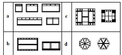
Generally speaking, wind catchers can be found in the eastern regions such as Iraq, Afghanistan, Pakistan, and Iran. In Iran they come in variety of cross sections and forms in Iran (Fig. 2) such as circle, octagon, polygon, square and rectangle. However, no triangular wind catcher can be found in the Middle East [19]. Wind catcher with a circular plan is very rare and such type of wind catchers were not used in common houses. One, two and four directional wind towers usually have rectangular plans whereas the square form is used in the four directional wind towers. Eight directional wind towers are those with an octagonal plan.
Fig. 2. Categorization of wind catchers.
4.
CFD Simulations
In this study Fluent Computational Fluid Dynamics (CFD) package is employed. There are a number of
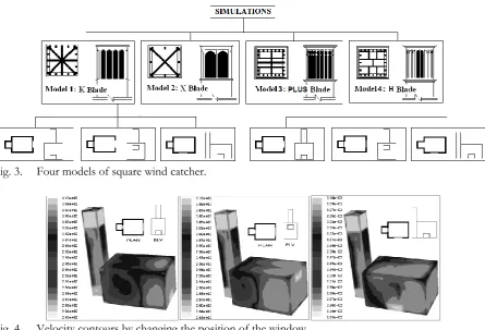
[image:4.595.174.419.76.186.2] [image:4.595.187.412.332.525.2]Fig. 3. Four models of square wind catcher.
Fig. 4. Velocity contours by changing the position of the window.
5.
Mathematical Model Setup
5.1. Geometrical Model
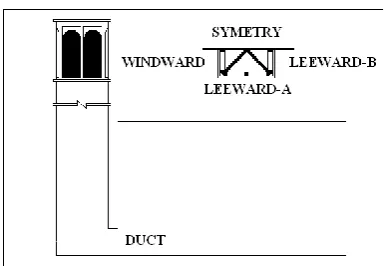
As shown in Fig. 5, a three dimensional square wind catcher model of dimension 150cm by 150cm with a height of 8.5 is connected to a 6 by 4 room. Outdoor temperature and wind speed were set at 310 Kelvin degrees and 5 m/s, respectively, with wind angle of 0 degree. The only variable was the geometry of the wind catcher plan. The geometry of these models were generated by Gambit 2.4 software and simulated with Fluent 6.3. In order to reduce the bulk of the simulations, half geometry with a symmetry plane was used and the number of mesh was increased for accurate results. The dimension of the domain was 100m
length, 23.5 m width and 28.5 heights which had a volume of 67000 m3.
[image:5.595.74.520.76.379.2] [image:5.595.151.447.549.731.2]5.2. Mesh Design and Boundary Condition
The k-ɛ model was adopted as a viscous model which is the best choice in solving an out region flow by
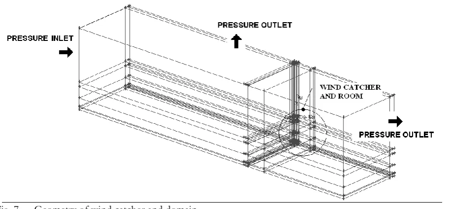
medium mesh size [21]. The total number of grid in all simulations was approximately 2600000. Structured hexahedral mesh which had stretched over the wind catcher edges was used for the models (Figs. 6 and 7). The pressure inlet boundary condition was assumed for the entrance air and the pressure outlet was assumed for the exit air.
Fig. 6. Side and front elevation of wind catcher geometry with hexahedral structural mesh.
Fig. 7. Geometry of wind catcher and domain.
6.
Results
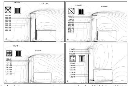
[image:6.595.75.521.173.303.2] [image:6.595.73.530.348.560.2]Fig. 8. Air velocity contours in horizontal plane in square wind catchers: a) X-blade form; b) K-blade form; c) plus blade form; d) H blade form.
[image:7.595.93.501.80.307.2] [image:7.595.85.505.355.636.2]Fig. 10. CFD simulation result reference.
Table 1. CFD simulation result.
Blade form X K PLUS H
Air velocity on windward 0.88 0.86 1.11 0.67
Mass flow rate on windward -1.10 -1.08 -1.34 -0.90
Mass flow rate on duct 0.20 0.24 0.90 0.20
Mass flow rate on surface A 0.55 0.54 0.53 0.49
Mass flow rate on surface B 0.32 0.29 0.65 0.31
To validate the CFD results, Mahyari’s [3] experimental results were used. The study was accomplished in a boundary layer wind tunnel using a scaled model of typical courtyard house equipped with a number of wind catchers. In Mahyari’s experiment, a “cross” shape square based design of a wind catcher attached to a model of a house was examined which was the same as CFD model. To determine velocity and velocity coefficient in each individual shaft, four probes of anemometers, depending upon the numbers of the shafts, were used in the centre of each shaft vertically. For the purpose of comparison, the air velocity value from CFD simulation changes to velocity coefficient. The velocity coefficient which is a dimensionless value is defined as the ratio of the value of velocity at the point of interest to the value at the reference height represented in Eq. (1).
=
(1)
where is the mean or peak wind speed at the point of interest and is the mean or peak wind speed
at the reference height. Table 2 shows a comparison between the measured and calculated velocity coefficient through windward and leeward of the wind catcher at air incident angle of 0º. Generally good agreements were achieved.
Table 2. Comparison of velocity coefficient for different angle of wind in CFD and wind tunnel experiment.
Case Windward Leeward (B) Leeward (A)
EXP. +0.97 -0.55 -0.39
CFD +1.09 -0.56 -0.46
7.
Conclusions
[image:8.595.202.396.76.209.2] [image:8.595.76.463.252.334.2] [image:8.595.175.418.569.607.2]References
[1] M. M. Zarandi, “Analysis on Iranian wind catcher and its effect on natural ventilation as a solution towards sustainable architecture (Case Study: Yazd),” Eng Technol, vol. 54, pp. 574-579, 2009.
[2] S. Roaf, Wind Catchers, Living With the Desert, E. Beazley, Ed., England: Air&Philips, 1982.
[3] A. Mahyari, “The wind catcher: A passive cooling device for hot arid climate,” Ph.D. thesis, Department of Architecture, Sydney University, 1996.
[4] O. Saadatian, L. C. Haw, K. Sopian, and M. Y. Sulaiman, “Review of windcatcher technologies,”
Renewable and Sustainable Energy Reviews, vol. 16, no. 3, pp. 1477-1495, 2012.
[5] M. Mahmoudi and S. M. Mofidi, “Investigation of architecture of wind-tower's plan on the environmental temperature reduction,” Journal of Environmental Science and Technology, vol. 13, no. 1(48), pp. 83-91, 2011.
[6] E. Beazley, M. Harverson, and S. Roaf, Living with the Desert: Working Buildings of the Iranian Plateau. Warminster: Aris & Phillips, 1982.
[7] M. Mahmoudi and S. M. Mofidi Shemirani, “Finding records of wind catcher in order to demonstrate of its Iranian identity,” Journal of Hoviteshahr, vol. 2, no. 2, pp. 25-33, 2008.
[8] A. A’zami, “Badgir in traditional Iranian architecture,” in Proceedings ofInternational Conference “Passive and Low Energy Cooling for the Built Environment, Santorini, Greece. 2005.
[9] M. N. Bahadori, “An improved design of wind towers for natural ventilation and passive cooling,”
Solar Energy, vol. 35, no. 2, pp. 119-129, 1985.
[10] M. Bahadori, “Passive cooling systems in Iranian architecture,” Science American, United States, vol. 238, no. 2, 1978.
[11] O. S. Asfour and M. B. Gadi, “A comparison between CFD and Network models for predicting wind-driven ventilation in buildings,” Building and Environment, vol. 42, no. 12, pp. 4079-4085, 2007.
[12] A. A. Elmualim, “Dynamic modelling of a wind catcher/tower turret for natural ventilation,” Building Services Engineering Research and Technology, vol. 27, no. 3, pp. 165-182, 2006.
[13] A. A. Elmualim and H. B. Awbi, “Wind tunnel and CFD investigation of the performance of wind catcher ventilation systems,” International Journal of Ventilation, vol. 1, no. 1, pp. 53-64, 2002.
[14] C. Karakatsanis, M. N. Bahadori, and B. Vickery, “Evaluation of pressure coefficients and estimation of air flow rates in buildings employing wind towers,” Solar Energy, vol. 37, no. 5, pp. 363-374, 1986. [15] M. Bahadori, M. Mazidi, and A. Dehghani, “Experimental investigation of new designs of wind
towers,” Renewable Energy, vol. 33, no. 10, pp. 2273-2281, 2008.
[16] Y. Bouchahm and A. Djouima, “The experimentation of improved evaporative cooling wind tower in real office building,” presented at PLEA 2008–25th Conference on Passive and Low Energy Architecture, Dublin, October 2008.
[17] S. Liu, C. Mak, and J. L. Niu, “Numerical evaluation of louver configuration and ventilation strategies for the windcatcher system,” Building and Environment, 2011.
[18] A. A. Badran, “Performance of cool towers under various climates in Jordan," Energy and buildings, vol. 35, no. 10, pp. 1031-1035, 2003.
[19] M. Mahmoudi and S. Mofidi Shemirani, “Analyze on typology and architecture of wind catcher and find the best type,” Journal of Honar-haye-ziba, no. 36, pp. 27-36, 2009.
[20] L. Anetor, E. Osakue, and C. Odetunde, “Reduced mechanism approach of modeling premixed propane-air mixture using ANSYS Fluent,” Engineering Journal, vol. 16, no. 1, pp. 67-86, 2011.
[21] Y. Tominaga, A. Mochida, R. Yoshie, H. Kataoka, T. Nozu, M. Yoshikawa, and T. Shirasawa, “AIJ guidelines for practical applications of CFD to pedestrian wind environment around buildings,”