Abstract—Simultaneous generation of microwave and millimeter-wave (mm-wave) signals is demonstrated experimentally using a 1310-nm Quantum Dot (QD) Distributed-Feedback (DFB) Laser. The reported technique is based on the period-1 dynamics and dual-mode lasing induced in the laser device under external optical injection. Tunability of the generated microwave and mm-wave signals is obtained. Furthermore, abrupt switching between different frequency regimes in the microwave and mm-wave bands is also observed. These novel frequency switching mechanisms added to the tuning capability of the system offers exciting prospects for novel uses of QD lasers in ultra-high frequency applications. Our approach also benefits from a simple experimental configuration using basic optical fibre components making our technique totally compatible with optical telecommunication networks.
Index Terms—Quantum Dot Laser, Microwave, Millimeter-wave, Optical Injection.
I. INTRODUCTION
hotonic techniques for the generation of ultra-high frequency (UHF) signals extending from the microwave to the millimeter-wave (mm-wave) and TeraHertz (THz) frequency ranges are undergoing considerable research effort. These are expected to have ample impact given their important advantages in comparison to electronic techniques (i.e. lower cost, reduced complexity, large frequency tunability, etc). Therefore, the combination of Radio Frequency (RF) and photonic technologies for the development of stable and tunable photonic microwave, mm-wave and THz sources is expected to play a key role in a wide range of future
Manuscript received January 31, 2015. This work was supported in part by the University of Strathclyde under the Chancellor’s Fellowships Programme (Starter Grant-Institute of Photonics) and the European Union Seventh Framework Programme (FP7/2007-2013) under grant agreement n° PIOF-GA-2010-273822.
A. Hurtado is with the Institute of Photonics, University of Strathclyde, Wolfson Centre, 106 Rottenrow East, Glasgow, G4 0NW, UK (phone: +44(0)141 390 4668; e-mail: [email protected]).
I.D. Henning and M.J. Adams are with the School of Computer Science and Electronic Engineering, University of Essex, Wivenhoe Park, Colchester, CO4 3SQ, United Kingdom.
R. Raghunathan and L.F. Lester are with the Bradley Department of Electrical and Computer Engineering, Virginia Tech, Blacksburg, VA.
applications. These include Radio-over-Fiber (RoF) optical wireless networks, mobile communication systems, satellite telecommunications, etc. For a review on the topic of microwave photonics, see for instance [1]–[3] and references therein.
One of these photonic approaches considers the use of optical injection in different types of semiconductor lasers for the generation of RF signals [3-4]. Optical injection permits the generation of tunable RF signals whilst simultaneously benefitting from a simple experimental configuration and the potential use of inexpensive commercial devices. Single- and double-optical injection schemes have been successfully reported to generate RF signals with frequencies ranging from a few GHz to over 100 GHz [3]–[12]. Moreover a range of functionality is offered; large frequency tunability [3-12], single- (SSB) and double side band (DSB) [8][13] and frequency modulation (FM) formats, as well as AM-to-FM conversion [9].Several works have reported on the generation of microwave signals mainly using Quantum Well (QW) lasers [3-9]. More recently, the use of Quantum Dot (QD) lasers for microwave and mm-wave signal generation has also started to receive interest [10][12-17] in view of the theoretically superior properties of QD devices (i.e. reduced temperature dependence of the lasing threshold, lower linewidth, faster dynamics, etc. [18-20]). Several works have reported on RF signal generation using mode-locking [14] or optical heterodyning approaches [15][16]. Nevertheless, apart from a few reports, the use of optical injection in QD lasers for RF signal generation has not received much attention. Early work included the use of an optically-injected 1550 nm Fabry– Perot (FP) Quantum Dash laser [10] to generate microwave signals. Very recently, a 1310-nm QD Distributed Feedback (DFB) laser subject to external optical injection into its lasing mode was utilized to generate continuously tunable microwave and mm-wave signals from below 1 to over 40 GHz [12]. Moreover, dual-mode lasing operation was demonstrated experimentally in such a device when subject to single optically injected signal [17]. This novel technique was used to generate tunable mm-wave and THz signals from 119 GHz to 954 GHz [13].
In this work, we report a first experimental demonstration of the simultaneous generation of microwave and mm-wave signals using a 1310-nm QD DFB laser subject to double optical injection [21]. Furthermore, tunability of both
Simultaneous Microwave and Millimeter-wave
Signal Generation with a 1310-nm Quantum
Dot Distributed Feedback Laser
A. Hurtado, R. Raghunathan, I.D. Henning, M.J. Adams and L.F. Lester, Fellow, IEEE
manipulation.
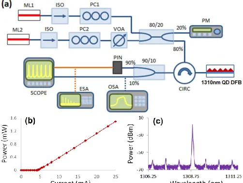
Fig. 1. (a) Experimental setup; (b) Light-Current (LI) curve at 298 K and (c) optical spectrum (at IBias = 5 mA) of the 1310nm QD DFB laser; ISO =
Isolator, PC = Polarization Controller; VOA = Variable Optical Attenuator, PM = Power Meter, ESA/OSA = Electrical/Optical Spectrum Analyser.
II. EXPERIMENTAL SETUP
Fig. 1(a) shows the experimental setup used to inject light from two Master Lasers (ML1 and ML2) into the 1310-nm QD DFB laser (Slave Laser, SL) in this work. The light-current (LI) curve of the SL measured at 298 K is plotted in fig. 1(b) showing a threshold current of 4.4 mA. The SL’s spectrum when biased just above threshold (IBias = 5 mA) is shown in fig. 1(c) depicting a single lasing mode around 1309 nm as well as the residual Fabry-Perot (FP) modes. For complete details on the QD DFB laser of this work see [12].
The emission wavelengths of ML1 and ML2 are individually tuned so that their light is injected into the SL’s lasing (ML1) and first longer wavelength residual FP mode (ML2). Two optical isolators are included after ML1 and ML2 to avoid backward reflections that could lead to spurious results. Also, two polarization controllers (PC1 and PC2) are respectively included after ML1 and ML2 to match their polarization state to that of the injected modes of the SL. Additionally, a Variable Optical Attenuator (VOA) was also included after ML2 for control of injection strength. The light of both MLs is combined together using an 80/20 fibre directional coupler. The 20% port is connected to a power meter to monitor the injection strength, whereas the 80%
orange lines denote electrical ones.
III. EXPERIMENTAL RESULTS
Figs. 2(a) and 2(b) show respectively the optical and electrical spectra of the 1310-nm QD DFB laser under the external injection of a single optical signal (from ML1) into its lasing mode. A bias current of 55 mA (~12.5Ith) was applied to the QD DFB laser. The injection strength of the externally injected signal was set equal to Pinj_ML1 = 1.85 mW, whereas the initial frequency detuning between the externally injected signal and the device’s lasing mode was configured equal to
[image:2.612.47.298.215.404.2]Fig. 2. Optical (a & c) and electrical (b & d) spectra of the 1310nm-QD DFB laser subject to single (a & b) and double (c & d) optical injection. The insets in in (c) show in detail the four individual peaks appearing in the optical spectrum for the double injection case.
Fig. 3. (a & b) Superimposed optical spectra measured for different values of injection strength plotting in detail the lasing line (a) and the injected residual FP mode (b). The QD DFB laser was subject to double optical injection with initial frequency detunings equal to: Δf1 = fML1 – fLasing-SL = 0 GHz and Δf2 =
fML2 – fSL-FP = 0 GHz and with increasing ML2’s injection strength from 0.71 mW (blue) to 1.22 mW (red) and 1.44 mW (green). (c & d) Frequency of the generated microwave (c) and mm-wave (d) signals vs. the injection strength from ML2. The blue, red and green dots in (c & d) correspond to the injection strength values used to measure the spectra in (a & b).
Furthermore, in addition to this dual-mode lasing response, the injection of the second optical signal from ML2 pushes the resonance frequency of the QD DFB laser towards longer wavelengths [12][17]. Due to this effect the lasing mode of the device is no longer locked to the initially injected signal from ML1. On the contrary, its response switches from stable locking to period-1 dynamics [12]. The latter are characterized by the generation of single frequency periodic oscillations in the microwave or lower mm-wave frequency ranges [12]. For the case investigated in fig. 2 the frequency of the generated microwave signal is equal to ~ 4 GHz as observed in the electrical spectrum plotted in fig. 2(d), measured under the same conditions as those used in fig. 2(c). Meanwhile,
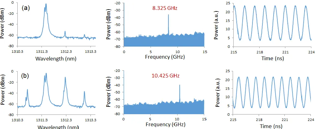
[image:3.612.53.295.248.468.2]Fig. 4. Optical (left)/Electrical (middle) Spectra and measured time series (right) of the 1310nm-QD DFB when the device is operated under single (a) and double (b) optical injection with increasing values of ML2’s injection strength. (a) The injection strength and initial frequency detuning for the signals injected from ML1 and ML2 were set equal to {Pinj_ML1 = 1.57 mW ; Δf1 = fML1 – fLasing-SL = +6 GHz} and{Pinj_ML2 = 0.38 mW ; Δf2 = fML2 – fSL-FP = -4 GHz} respectively.
It should be noted that the electrical bandwidth of the experimental setup was limited by that of the PIN photodiode ~12GHz. Frequency values above this were measured indirectly using the OSA to determine the frequency difference of lasing lines in the optical spectrum for various injection conditions. It should also be mentioned that the frequency values indicated in fig. 3(d) correspond to those of the mm-wave signals with highest expected power. After the threshold level of 1.39 mW is exceeded the lasing mode switches from a stable locking to a period 1 dynamics response, (see fig. 2(c) and fig. 3(a)) exhibiting two peaks of relative high intensity: the main peak and the lower wavelength side band. Thus, two mm-wave signals at 133 GHz and at 137 GHz, would be simultaneously generated as a result of beating with the residual FP mode of the QD laser. However, as the main peak is at least 3 dB above that of the lower side band the beat intensity of the two generated mm-wave signals would be significantly different, being greatest at 133 GHz and lower at 137 GHz. This difference in the intensity of these mm-wave signals, explains the abrupt frequency switching observed from 137 GHz to 133 GHz in fig. 3(d) as the threshold value is exceeded.
Fig. 4 shows results for another case where different values of initial frequency detuning are set for the two externally injected signals. Fig. 4 includes measured optical (left plots) and electrical (middle plots) spectra as well as captured time series (right plots) for two different scenarios. Specifically, fig. 4(a) plots measured results when single optical injection from ML1 is applied into the lasing mode of the device. The signal from ML1 injected into the SL’s lasing mode is configured now with a power of Pinj_ML1 = 1.57 mW and an initial frequency detuning of Δf1= fML1 – fLasing-SL = +6 GHz. Fig. 4(a) shows for this new case that initially the lasing mode is not injection-locked to the signal from ML1 (as it was in fig. 2(a)) but now the system’s output is characterized by a period-1 dynamics regime [period-12]. Thus a microwave signal at a
frequency of 8.325 GHz is already obtained when the device is subject to single optical injection. This behaviour is characterized by the appearance of side-bands in the optical spectrum around the SL’s main lasing peak, and a clear peak in the electrical spectrum at the generated frequency. Also, the measured time series show high-excursion periodic oscillations at the frequency of the generated microwave signal. Now, a second optical signal from ML2 is injected into the first longer wavelength residual FP mode of the QD DFB laser with an initial frequency detuning equal to -4 GHz. Fig. 4(b) plots measured optical (left) and electrical (middle) spectra and time series (right) for this double optical injection scenario. Specifically, Fig. 4(b) which plots the case where this second optical signal is configured with an optical power of 0.38 mW shows that the injection of the second signal produces a dual-mode lasing response. Therefore, in addition to the previously generated microwave signal (see fig. 4(a)) a mm-wave signal is also generated at a frequency equal to the difference between the two lasing peaks (≈ 136 GHz) appearing in the optical spectrum of fig. 4(b). However, the injection of the second signal pushes the SL’s resonance towards longer wavelengths, increasing the detuning between the latter and the injected signal from ML1 and thus the frequency of the generated microwave signal increases from 8.325 GHz to 10.425 GHz. This is better seen from the electrical spectrum of fig. 4(b) showing that shift towards a higher frequency at 10.425 GHz. Finally, the time series measured for the case analyzed in fig. 4(b) still show high-excursion periodic oscillations at the new frequency.
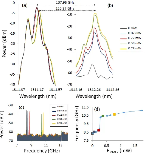
[image:4.612.51.561.50.259.2]spectra of fig. 4. Figs. 5(a) and 5(b) reveal that the frequency of the generated mm-wave signals can be tuned from ~138 GHz to ~135.9 GHz as the injection strength is increased due to the pushing of the SL’s lasing peak towards longer wavelengths with increasing injection strength. Fig. 5(c) plots superimposed electrical spectra measured for the same input power values used in figs. 5(a) and 5(b) showing the increase in the frequency of the generated microwave signal with injection strength. This is shown in fig. 5(d) plotting the frequency of the generated microwave signal as a function of the injection strength. The colored squares in fig. 5(d) mark the input power values used to measure the optical and electrical spectra in figs. 5(a-c). Fig. 5(d) shows that in addition to the frequency tuneability an abrupt switching transition is also observed in the frequency of the generated microwave signals when the input power exceeds 0.28 mW. This switching point, which marks a transition between two oscillatory regimes at different frequency bands occurs as a result of the locking of the residual FP mode to the injected signal from ML2.
Fig. 5. (a & b) Superimposed optical spectra of the 1310nm-QD DFB laser plotting in detail the lasing line (a) and the injected residual FP mode (b). The device was subjected to double optical injection for initial frequency detuning equal to: Δf1 = fML1 – fLasing-SL = +6 GHz and Δf2 = fML2 – fFP-SL = -4 GHz with input power from ML2 increasing from 0 to 0.78 mW as indicated. (c) Superimposed electrical spectra for the same input power values as indicated. (d) Frequency of the generated microwave signals as a function of the ML2’s injection strength. The large colored squares in (d) mark the in power values used to measure the optical and electrical spectra in (a-c).
IV. DISCUSSION
The results in figs. 2-5 show the important effect played by the initial frequency detuning and injection strength in the frequency values of the generated microwave and mm-wave signals. In fact, controlling the values of these two system
parameters can be used as a simple and effective technique to continuously tune the frequency of both generated microwave and mm-wave signals within a certain window [12][13]. Moreover, controlling the value of the initial frequency detuning of the signal injected into the device’s lasing mode plays a critical role in the initial state of the system. It is well known that in addition to stable locking a rich variety of nonlinear dynamics (including, period 1, period 2, chaos, etc.) can be obtained in an semiconductor laser by controlling the injected initial frequency detuning (see for instance [22]). Interestingly, for the QD DFB laser used in the experiments and the selected applied bias current only period 1 dynamics are obtained outside the locking range [12]. Therefore, the control of the initial frequency detuning of the first injected signal (from ML1) offers a series of competitive advantages for the technique reported in this work. First, it configures a very simple way to control the initial state of the system between only two different states depending on the desired application: stable locking (figs. 2-3) or period 1 dynamics (figs. 4-5). For the latter case the frequency of the generated microwave signal could be also controlled by properly adjusting the initial detuning [12]. We must also note that given the lack of regions of more complex dynamics (such as period 2 or chaos) outside the QD laser’s locking range there are no undesirable tuning gaps and therefore the entire frequency detuning range could in principle be used for the purpose of microwave signal generation [12].
In parallel, the results plotted in Figs 3 and 5 clearly demonstrate the effect of the injection strength in tuning the frequency of both microwave and mm-wave signals. This is due to the push towards longer SL’s lasing wavelength with rising input power. The effect is as follows: the higher the injection strength, the higher is the number of carriers recombined in the active region of the device which in turn reduces its refractive index. As a result the wavelength of the SL’s lasing peak increases, thus allowing the tunability of the generated microwave and mm-wave signals as it modifies the frequency difference between the injected signals and the QD DFB’s resonance. Finally, although the study of the frequency stability of the generated signals is beyond the scope of this work we believe that similar values of linewidth (in the order of a few MHz) to those obtained with QW devices [3-6] are also expected for the signals generated here with a QD device. Nevertheless, further theoretical and experimental analyses are needed to confirm these initial predictions.
V. CONCLUSIONS
[image:5.612.51.296.306.562.2]others AM-to-FM conversion, switching between different frequency bands and microwave-to-mm-wave conversion.
Finally, the simplicity of the experimental configuration, requiring just one SL and off-the-shelf fiber optic components offers great potential for novel applications of QD lasers in disparate fields requiring the generation of UHF signals at different frequency bands, such as optical wireless networks and spectroscopy. Furthermore, the use of a device emitting at the important telecom wavelength of 1310nm makes our approach compatible with present and future optical telecommunication networks.
REFERENCES
[1] A. Seeds and K. J. Williams, “Microwave photonics,” J. Lightw. Technol., vol. 24, no. 12, pp. 4628–4641, Dec. 2006.
[2] D. Marpaung, C. Roeloffzen, R. Heideman, A. Leinse, S. Sales, and J. Capmany, “Integrated microwave photonics,” Laser Photon. Rev., pp. 1–33, 2013.
[3] X. Q. Qi and J. M. Liu, “Photonic microwave applications of the dynamics of semiconductor lasers,” IEEE J. Sel. Topics Quantum Electron., vol. 17, no. 5, pp. 1198–1211, Sep./Oct. 2011.
[4] S. C. Chan, “Analysis of an optically injected semiconductor laser for microwave generation,” IEEE J. Quantum Electron., vol. 46, no. 3, pp. 421–428, Mar. 2010.
[5] Y. S. Juan and F. Y. Lin, “Photonic generation of broadly tunable microwave signals utilizing a dual-beam optically injected semiconductor laser,” IEEE Photon. J., vol. 3, no. 4, pp. 644–650, Aug. 2011.
[6] A. Quirce and A. Valle, “High-frequency microwave signal generation using multi-transverse mode VCSELs subject to two-frequency optical injection,” Opt. Exp., vol. 20, no. 12, pp. 13390–13401, Jun. 2012. [7] G. J. Schneider, J. A. Murakowski, C. A. Schuetz, S. Shi, and D. W.
Prather, “Radiofrequency signal-generation system with over seven octaves of continuous tuning,” Nat. Photon., vol. 7, pp. 118–122, 2013. [8] S. C. Chan and J. M. Liu, “Frequency modulation on single sideband
using controlled dynamics of an optically injected semiconductor laser,” IEEE J. Quantum Electron., vol. 42, no. 7, pp. 699–705, Jul. 2006. [9] S. C. Chan, S. K. Hwang, and J. M. Liu, “Radio-over-fiber AM-to-FM
up-conversion using an optically injected semiconductor laser,” Opt. Lett., vol. 31, no. 15, pp. 2254–2256, Aug. 2006.
[10] M. Pochet, N. A. Naderi, Y. Li, V. Kovanis, and L. F. Lester, “Tunable photonic oscillators using optically injected quantum-dash diode lasers,” IEEE Photon. Technol. Lett., vol. 22, no. 11, pp. 763–765, Jun. 2010. [11] M. Pochet, T. Locke, and N. G. Usechak, “Generation and modulation
of a millimeter-wave subcarrier on an optical frequency generated via optical injection,” IEEE Photon. J., vol. 4, pp. 1881–1891, Oct. 2012. [12] A. Hurtado, J. Mee, M. Nami, I.D. Henning, M.J. Adams and L.F.
Lester, “Tunable microwave signal generator with an optically-injected 1310nm QD-DFB laser,” Opt. Exp., vol. 21, no. 9, pp. 10772-10778, May 2013.
[13] A. Hurtado, I.D. Henning, M.J. Adams and L.F. Lester, “Generation of Tunable Millimeter-Wave and THz Signals With an Optically Injected Quantum Dot Distributed Feedback Laser,” IEEE Photonics Journal 5, 5900107 (2013)
201117-1–201117-4, May 2013.
[18] P. Bhattacharya, D. Klotzkin, O. Qasaimeh, W. Zhou, S. Krishna, and D. Zhu, “High-speed modulation and switching characteristics of In(Ga)As-Al(Ga)As self-organized quantum-dot lasers,” IEEE J. Sel. Topics Quantum Electron., vol. 6, no. 3, pp. 426–438, May/Jun. 2000. [19] H. Y. Liu, T. J. Badcock, K. M. Groom, M. Hopkinson, M. Gutierrez, D.
T. Childs, C. Jin, R. A. Hogg, I. R. Sellers, D. J. Mowbray, M. S. Skolnick, R. Beanland, and D. J. Robbins, “High-performance 1.3 m InAs/GaAs quantum-dot lasers with low threshold current and negative characteristic temperature,” in Proc. SPIE, 2006, vol. 6184, p. 618417. [20] T. C. Newell, D. J. Bossert, A. Stintz, B. Fuchs, K. J. Malloy, and L. F.
Lester, “Gain and linewidth enhancement factor in InAs quantum-dot laser diodes,” IEEE Photon. Technol. Lett., vol. 11, no. 12, pp. 1527– 1529, Dec. 1999.
[21] A. Hurtado, I.D. Henning, M.J. Adams and L.F. Lester, “Simultaneous generation of tuneable microwave and millimeter-wave signals with a 1310nm QD DFB laser”, IEEE International Semiconductor Laser Conference, ISLC 2014, Palma de Mallorca (Spain), September 2014. [22] A. Hurtado, A. Quirce, A. Valle, L. Pesquera and M.J. Adams,
“Nonlinear dynamics induced by parallel and orthogonal optical injection in 1550 nm Vertical-Cavity Surface-Emitting Lasers (VCSELs)”, Optics Express, 18 pp. 9423-9428 (2010)
[23] H. Su, H. Li, L. Zhang, Z. Zou, A. L. Gray, R. Wang, P. M. Varangis, and L. F. Lester, “Non degenerate four-wave mixing in quantum dot distributed feedback lasers,” IEEE Photon. Technol. Lett., vol. 17, no. 8, pp. 1686–1688, Aug. 2005.
[24] Millimeter Wave Propagation: Spectrum Management, Federal Communications Commission, Office of Engineering and Technology, Washington, DC, USA, Bull. 70, 1997.
[25] Y. Yang, A. Shutler, and D. Grischkowsky, “Measurement of the transmission of the atmosphere from 0.2 to 2 THz,” Opt. Exp., vol. 19, no. 9, pp. 8830–8838, Apr. 2011.
Antonio Hurtado received his PhD degree in Telecommunications Engineering from the Universidad Politécnica de Madrid (Spain) in 2006. In 2007 he joined the Optoelectronics Research Group at the University of Essex (UK) and from 2011 to 2013 he worked at the Centre for High Technology Materials, University of New Mexico (USA). He has been awarded two consecutive Marie Curie Fellowships by the European Commission. In 2014 he was appointed as Lecturer (Chancellor’s Fellowship) in the Institute of Photonics of the University of Strathclyde (Glasgow, Scotland, UK).
physics and characterization of semiconductor lasers, such as pulse compression and noise performance improvement in passively mode-locked quantum dot lasers, ultrafast pulse characterization, nonlinear dynamical effects in semiconductor lasers, and the investigation of novel phenomena, such as nonlinear and quantum optical effects in semiconductor nanostructures.
Ian D. Henning received the degree in applied physics and the Ph.D. degree from the University of Wales, Cardiff, U.K. In 1980, he joined British Telecom Research Laboratories at Martlesham Heath, working on the design and characterisation of a range of optoelectronic devices and photonic integrated circuits. In 2002 he joined University of Essex, Colchester, U.K as a Professor.
Michael J. Adams received the Ph.D. degree in laser theory from the University of Wales, Cardiff, U.K., in 1970. He was engaged in optoelectronics research and development with 15 years of experience in industry (Plessey, BT), and 29 years of experience in academia (University of Cardiff, University of Southampton, University of Essex, Colchester, U.K.). Since 1996 he has been a Professor at the University of Essex.
Luke F. Lester (S’89-M’91-SM’01-F’13) received the B.S. in Engineering Physics in 1984 and the Ph.D. in Electrical Engineering in 1992, both from Cornell University. He is a Professor and Head of the Bradley Department of Electrical and Computer Engineering (ECE) at Virginia Tech and Editor-in-Chief of the IEEE JSTQE. Prior to joining Virginia Tech, he was a professor of ECE at the University of New Mexico (UNM) from 1994 to 2013, and most recently the Interim Department Chair and the Endowed Chair Professor in Microelectronics there. Before 1994, Dr. Lester worked as an engineer for the General Electric (Martin Marietta) Electronics Laboratory in Syracuse, New York for 6 years where he worked on transistors for mm-wave applications. There in 1986 he co-invented the first Pseudomorphic HEMT, a device that was later highlighted in the Guinness Book of World Records as the fastest transistor. By 1991 as a PhD student in Prof. Lester Eastman’s group at Cornell, he researched and developed the first strained quantum well lasers with mm-wave bandwidths. These lasers are now the industry standard for optical transmitters in data and telecommunications. In all, Dr. Lester has nearly 30 years experience in III-V semiconductor devices and advanced fabrication techniques. In 2001, he was a co-Founder and Chief Technology Officer of Zia Laser, Inc., a startup company using quantum dot laser technology to develop products for communications and computer/microprocessor applications. The company was later acquired by Innolume, GmbH. He was a US Air Force Summer Faculty Fellow in 2006 and 2007. Dr. Lester’s other awards and honors include: a 1986 IEE