City, University of London Institutional Repository
Citation
:
MacFarlane, A., McCann, J. A. and Liddell, H. (1996). A Common Data Model for Meta-Data in Interoperable Environments. Paper presented at the 2nd international Baltic conference on IS and DB, 12-06-1996 - 14-06-1996, Tallinn, Estonia.This is the accepted version of the paper.
This version of the publication may differ from the final published
version.
Permanent repository link:
http://openaccess.city.ac.uk/4447/Link to published version
:
Copyright and reuse:
City Research Online aims to make research
outputs of City, University of London available to a wider audience.
Copyright and Moral Rights remain with the author(s) and/or copyright
holders. URLs from City Research Online may be freely distributed and
linked to.
A Common Data Model For Meta-Data
in Interoperable Environments
A.MacFarlane*, J.A.McCann +, H.Liddell*
* London Parallel Application Centre, Queen Mary & Westfield College,
University of London , Mile End Road, LONDON E1 4NS + SARC, City University, Northampton Square, London EC1V 0BH
Abstract
A Common Data Model is a unifying structure used to allow heterogeneous environments to interoperate. An Object Oriented common model is presented in this paper, which provides this unifying structure for a Meta-Data Repository Visualisation Tool. The creation of this common model from the Meta-Data held in component databases is described. The role this common model has in interoperable environments is discussed, and the physical architecture created from the examination of the Meta-Data in the Repository common model is described.
1 Introduction
Many Interoperable Database Management systems utilise a Common Data Model as a
single structure which all of the components use, allowing application programs to
access data transparently i.e. the Data Model in the component databases are
transparent. The common model is not only a conflict resolution structure but also a
way to describe the complete data resource held in many heterogeneous data sources.
This paper focuses on the common model of a Meta-Data Repository Visualisation
Tool being designed and built for the HPC/SEA/Iriss project [1].
HPPC/SEA/IRISS is a Eureka project which is concerned with applications that
manipulate large volumes of data. Issues in IRISS centre around areas such as decision
support, on-line transaction processing and system interoperability, with a special focus
on obtaining optimum performance. In this project the partners are aiming to provide
an architecture which is capable of supporting the necessary data volumes and levels of
processing required to support both mission critical applications and decision support
applications. IRISS is based on a former UK Advanced technology project, IDIOMS
[2], which was a two year project to develop a database engine with supporting
UK Bank). The underlying machine used in the IRISS project is the IDIOMS database
Machine.
New technologies are required to support the demands of inter-application data
sharing. The requirement is a new lightweight mechanism that allows dynamically
constructed data to be transferred between any set of applications and a set of databases
anywhere on the network running in any environment. This is currently achieved
through the use of middleware which provides the overall support for standard
interfaces. There is a requirement for database tools to manage this middleware.
Consequently one of the major project tasks concerns the provision of a set of portable
reusable tools to be used in heterogeneous environments to aid database administration,
to help optimise the database through monitoring and visualisation facilities and to
interface different databases. This is the task in which the LPAC (London Parallel
Application Centre) group is involved; the tools we are developing include a database
monitoring tool and the Repository. The Repository together with Strand Software
Technologies Clearinghouse system [3] will be the 'glue' which ties all the disparate
databases together. A key element of the Repository is the common model.
The organisation of the paper is as follows. Section 2 describes the Repository.
Section 3 describes the Clearinghouse system. Section 4 describes the common model
and its component parts. The role of the common model in interoperable environments
is described in section 5. Section 6 describes the physical architecture of an
interoperable environment created by the examination of Meta-Data in the Repository
common model. A summary is given and further work needed is described in section 7.
2 The Meta-Data Repository Visualisation Tool
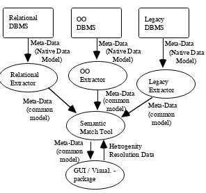
We have defined three main components of the Repository; an extraction
component, a semantic match tool and a graphical data visualisation tool. Figure 1
shows the relationship between the various components.
Extraction tools examine the Meta-Data and redefine its information in terms of
our common model. The semantic match tool takes this Meta-Data and resolves
semantic heterogeneity between the various Meta-Data. The visualisation component
will provide interaction facilities for the extraction and semantic match components, as
well as visualising the Meta-Data. The Repository will connect with the Clearinghouse
middleware system, using an Application Programming Interface, but has been
designed using an object model so that it will easily connect to an Object Request
Broker based middleware product. Once heterogeneity has been resolved, the
operational architecture for the interoperable environment can be generated (see section
6) using the Meta-Data created during the Schema Integration process and held in the
Relational DBMS OO DBMS Legacy DBMS Relational Extractor OO Extractor Legacy Extractor Meta-Data Meta-Data Meta-Data
Meta-Data
Meta-Data
Meta-Data Semantic
Match Tool
[image:4.595.154.450.74.352.2]GUI / Visual. - package Meta-Data Hetrogenity Resolution Data (Native Data Model) (Native Data Model) (Native Data Model) (common model) (common model) (common model) (common model)
FIGURE 1 - Repository Structure
3 The Clearinghouse System
The Clearinghouse system [3] is essentially a distributed event manager, where
data is pro-actively sent to clients. There are four main components to the
Clearinghouse system; the register, exchanges, probes and database agents. The register
records the location of Clearinghouse elements for client programs as well as storing
other details. An exchange holds information on a single, simple data model and with
which client programs connect to when given the location by the register. Probes are
reactive process which map data from one data model to another and connect
exchanges together. Database agents enable the clearinghouse system to connect with
component databases. We have conceptually designed the common model using the
Object-Oriented model, but physical storage of translation, functions etc. use
Clearinghouse.
4 Description of the Common Data Model
The Common Data Model is a recommended structure by which interoperable
environments can unify their disparate component databases, with varying native data
models. The actual model is given in Appendix II and the Object Notation [4] used is
given in Appendix I. This common model is the logical representation of Meta-Data.
legacy databases. Example coverage included the IBM IMS system [5] and the relational databases INGRES [6] and ORACLE [7]. The model to be used in the common model is Object Oriented which has the advantages; it provides a number of
useful abstraction mechanisms such as inheritance and aggregation, permits behaviour
of objects to be captured through methods, non-traditional databases can be integrated
using behavioural mappings and given that storage and retrieval is supported by the
underlying model efficiency is not greatly degraded [8]. The Object Oriented model is
becoming the dominant model in interoperable systems; previously many systems used
the relational model [9]. We have identified four main Meta-Data classes; Objects,
Constraints, Security and System. Each of these Meta-Data are described below.
4.1 Objects
The Object class refers to Meta-Data that users of all types use directly in
support of their functions e.g. end users need to know about the Meta-Data for the data
that their application program use to complete their task. The objects can be Tables,
Views, Reports, Forms, records, segments etc. The definition of Object has been
defined to take account of the various types of structures which are encountered in the
many native data models we examined. For example relational databases are made up
of relations (tables), which are in turn made up of attributes; hierarchical databases
have trees which are made up of segments, which are made up of attributes and links to
other segments. It is apparent that we can model these native data models using Object
Orientation. We use the process of Aggregation [4] to build up Object Oriented representations of these native models. The process of Generalisation [4] is used to build objects in the common model using the different representations built by the
Aggregation process. The advantage of this definition of Object is that the native data
model can be modeled naturally, while isomorphism's for the common model can be
formed from those disparate models. An isomorphism is defined by Hofstader [10] is
an information preserving-transformation where "two complex structures can be
mapped onto each other, in such a way that to each part of one structure there is a
corresponding part in the other structure, where 'corresponding' means that the two
parts play similar roles in their respective structures". Isomorphism creation can be
done by defining the extent which is the ability to define the set of objects which
belongs-to a class [8]. The relation belongs-to means that an operation can be done on a class "if it is an instance of that class or any of its subclasses" [8]. We use the term
isomorphism to mean the mapping of disparate data models to a single Object Oriented
data model in order to allow interoperation between them. Thus there are a number of
mappings needed to build isomorphism's. These Isomorphism's are built by resolving
4.2 Constraint
Constraint Meta-Data refers to constraints on Object Meta-Data such as unique
data within fields or a threshold for object occurrences e.g. an attribute
NUM_COMPONENTS would have the constraint > 0. This Meta-Data can be built
into the system, as found with IMS [5] or user defined. There appears to be occasions
when Constraint Meta-Data is defined on a on Object at the same time as Security e.g.
in ORACLE 6 the Meta-Data attribute CONTRAINT_COLUMNS refers to constraint
definitions on accessible tables. The extraction component of the Repository has to be
built with such information in mind.
4.3 Security
Security Meta-Data refers to the users ability to access to a particular object or
objects, more specifically identifies permissions to read, write, or update objects or
groups of users ability to access an object. As noted above the distinction between
Security and Constraint Meta-Data can sometimes be blurred. The security mechanism
is visible for an Object in the example given above, therefore the extraction process can
easily be implemented to accommodate such information. Where Security mechanisms
are built in to a Database Management System e.g. IMS [5] the distinction between
Security and Constraint Meta-Data could be harder to determine. This has implications
for the extraction tool where specific extractions will need to be built for a given
database, particularly for legacy systems such as IMS [5].
4.4 System
System Meta-Data refers to system administration data for databases. Examples
of this type of data are the physical storage for an object, object location, information
needed for recovery, network information (topology, site, address), logical to physical
mapping and performance.
4.5 Aggregate Classes
It should be noted that System, Security and Constraint Meta-Data applies to the
aggregate classes i.e. the attributes of a tables as well as the table itself. This means that
each sub-class may have its own Constraints, Security and System related Meta-Data.
A further important point is that there may be missing information in our representation
5 The Role of the Common Model in Interoperable
Environments
In [11] Seth and Larson describe a five level schema architecture for use in
Federated Database systems. Pitoura et al [8] take this architecture and adapt it to
include the data models for each schema. In this section we describe the role of the
common model in an interoperable environment in all levels of this five level
architecture.
The Local Schema of the pre-existing component database system uses the
native data model. The extraction process (or the Schema Translation process [11])
takes Meta-Data from this Local Schema and converts it into the common model of the
Component Schema. The relevant sub-class of that native data model is used to
populate the Component Schema. It should be noted that this is not the only strategy.
The Jupiter system [12] defines a Participation Schema in the place of the Component
Schema. Murphy and Grimson argue that to make available only those parts of a Local
Schema through the Export Schema (in our terms partial extraction) is more pragmatic.
Our approach is to populate the Component Schema with all the relevant Meta-Data, so
that the Meta-Data is available when a new federation is needed and no extra request by
a Database Administrator is needed to put the extra data in the system. While this is a
much more user friendly option, it is at the cost of extra redundancy of Meta-Data in
the Repository. However, Meta-Data will not be large relative to the data which it
describes. The local Database Administrator manages the Component Schema.
Once the Component Schema is set up, any Export Schema can defined for use
in Federated Schemas as and when they are required. The Export Schema common
model is a view over a subset of the Component Schemas common model; only that
which is required by the federation. It is the task of the local Database Administrator to
define this Export Schema, using negotiation with the Federated Database
Administrator (the negotiation process [11]).
When the Export schema common model's have been defined, the Federated
Database Administrator can create the Federated Schema common model by using the
process of Schema Integration [11] to unify the Export Schema common model's. An
important issue is the decideability of conflictfreeness when integrating schemas.
Conflictfreeness between any two schemas is defined the ability to determine that the
structure of the schemas do not conflict in any way. When conflictfreeness cannot be
decided between schemas the resultant effect is to render the integration of those
schemas problematic and any interoperation between them cannot be relied upon.
Convent [13] formally argues that conflictfreeness in the integration of two relational
ability to prove the conflictfreeness of any two schemas with any given data model.
However, Convent has only proved that conflictfreeness is undecidable at the level of
expressiveness for schema integration which he believes is the minimum needed . No
proof is given for the level of expressiveness he uses in the paper. It is therefore hard to
accept the validity of his proof one way or another, with knowing more about the level
of expressiveness needed for schema integration. For the sake of brevity the reader is
referred to Convents paper [13] for examples. In any case the formal model which
Convent uses [14] requires the use of a data model with clear formal semantics; the
latter will not probably not exist for legacy systems. We therefore believe that a formal
model must be derived in order reason about conflictfreeness of heterogeneous
integrated schemas. Unfortunately the lifetime of this project precludes the authors
from attempting this.
After the Federated Schemas have been defined with some level of
expressiveness which is conflict free, External Schemas with any data model can be
defined as views over those federations.
6 Physical Architecture for Interoperable Environments
The physical architecture of a interoperable environment (or Federated
Database system) is very dependant on the middleware to be used to implement it.
Examples are Clearinghouse [3] and CORBA [15]. We need to hide the details of the
architecture such that either of these systems could be used to implement the
Repository. Our aim is to provide some middleware portability. We present a
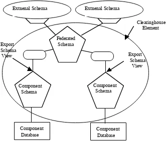
architecture for Clearinghouse in Figure 3, which we believe could be useful. The
Clearinghouse notation used is Strand Software Technologies' [3] which can be found
in Appendix III.
Two levels of the 5-level architecture are represented by Clearinghouse
exchanges, which contain the common model at that level. The probes between these
exchanges represent a mapping between each of exchanges of the various levels of the
architecture. The Repository will set up the exchanges with the relevant common model
and the probes with the model to model mappings, so that data can pass through them
in an operational environment. A view over the Component Schema is provided for
Export Schema implementation. An alternative would be to have an exchange to handle
the Export Schema, but this would mean that transactions would need to pass through
an extra exchange, with resultant loss of performance. The Federated exchange
provides a External Schema view using the Clearinghouse Application Programming
Interface for client programs. The advantage of the architecture in Figure 3 is that there
are no circular relationships between the exchanges, and therefore the risk of race
Federated Schema
Component Schema
Component Schema
Extnenal Schema Extnenal Schema
Component Database Export
Schema
View Export
Schema View
Clearinghouse Element
[image:9.595.127.458.59.343.2]Component Database
FIGURE 3 - Physical Architecture for Interoperable Environments
An alternative to Clearinghouse is CORBA [15]. We can replace the
Clearinghouse element shown in figure 3 by Object Request Brokers and provide a
standard interface with which to access the data. Given that our design will be based on
the Object-Oriented model, this would be a minor task. It should be noted however, that
some addition to CORBA would be needed to provide the same functionality as
Clearinghouse. This is because of the pro-activity of Clearinghouse which propagates
events around connected exchanges. The ISIS system [16] could provide the
pro-activity needed in conjunction with an Object Request Broker by using the concept of
process groups, in which processes notify each other of events as and when they occur.
7 Summary & Further Work
We have described the Common Data Model which will be used as the common
structure in the Meta-Data Repository Visualisation Tool being designed and
implemented for the purposes of the HPPC/SEA/Iriss project. Four main classes for
Meta-Data for a Object-Oriented common model have been identified; Object,
Constraints, Security and System. We believe the definition of Object is flexible
enough to model the structures of all types of databases. The role of the common model
in Federated Databases is discussed for each of the levels of Seth and Larsons 5-Level
schema architecture [11]. We present an architecture created from Meta-Data in the
only). We have designed the Repository using the Object Oriented model such that an
Object Request Broker product could be used in place of the Clearinghouse. The
importance of isomorphism creation is stressed in the paper. Information preserving
transformations are regarded as central to the success of integrating heterogeneous
databases. We have identified the need to derive a formal model in order to reason
about the decideability of conlictfreeness when integrating schemas in heterogeneous
environments. We hope that we will be able to undertake this task in the near future.
We are currently implementing the Repository using the common model structure
described in this paper. Extraction tools will take information from the native database
and put it in a suitable form for the common model. The semantic match tool will
provide the method for building federations. The GUI/visualisation tool will allow the
user to resolve heterogeneity interactively, as well as visualise the Meta-Data in the
Repository using a representation of the common model structure. The resultant
operational architecture for the Interoperable system can then be created from the
Meta-Data held in the repository; this will be an automatic process.
Acknowledgement
We are grateful to David Streader for helping us to clarify the concept of
isomorphism's.
References
[1] J. A. McCann, A. MacFarlane, H. Liddell, Management Tools for Distributed
Interoperable Environments, Proceedings of HPCN'96, Brussels, LNCS, Springer-Verlag, 1996.
[2] J.M. Kerridge, The Design of the IDIOMS Parallel Database Machine, BNCOD9, Wolverhampton, 1991.
[3] The Clearinghouse Data Management System, Strand Software Technologies Ltd,
UK.
[4] J. Rumbaugh, M. Blaha, W. Premerlani, F. Eddy, W. Lorensen, Object-Oriented
Modeling and Design, Prentice-Hall, 1991.
[5] W. C. McGee, The information management system IMS/VS, IBM System Journal,
[6] Appendix D, The INGRES System Catalogs, INGRES/SQL Reference Manual,
Ingres Corporation.
[7] ORACLE RDBMS Database Administrators Guide, Version 6.0, Oracle
Corporation 1990.
[8] E. Pitoura, O. Bukhres, A. Elmagarmid, Object Orientation in Multidatabase
systems, ACM Computing Surveys, Vol. 27, No. 2, June 1995.
[9] G. Thomas, G. R. Thompson, C. Chung, E. Barkmeyer, F. Carter, M. Templeton, S.
Fox, B. Hartman, Heterogeneous Distributed Database Systems for Production Use,
ACM Computing Surveys, Vol. 22, No. 3, September 1990.
[10] D. R. Hofstader, Godel, Escher, Bach: An Eternal Golden Braid, Penguin, 1979.
[11] A. P. Sheth, J. A. Larson, Federated Database Systems for Managing Distributed
Heterogeneous, and Autonomous Databases, ACM Computing Surveys, Vol. 22, No. 3, September 1990.
[12] J. Murphy, J. Grimson, The Jupiter System: A Prototype for Multidatabase
Interoperability, Directions in Databases: BNCOD 12, July 1994, Springer-Verlag.
[13] B. Convent Unsolvable Problems Related To The View Integration Approach,
Proceedings of ICDT'86, Lecture Notes in Computer Science, No 243. Springer-Verlag, 1986.
[14] J. Biskup, B. Convent, A Formal View Integration Method, ACM SIGMOD International Conference on Management of Data, 1986.
[15] The Common Object Request Broker (CORBA): Architecture and Specification,
Object Management Group, Document Number 91.12.1, Revision 1.1 1992.
[16] K. P. Birman, The Process Group Approach To Reliable Distributed Computing,
APPENDIX I - OBJECT MODEL NOTATION USED
+1
Class
Assocation of classes
Generalisation (Inheritance)
Aggregation
One or more assocations
APPENDIX II - THE COMMON DATA MODEL
constraints constraints
system
security
object
oo class relation heir. tree FF record
attributes attributes
attributes
segment attributes
+1 +1 +1 +1
APPENDIX III - CLEARINGHOUSE NOTATION
A Client Program Clearinghouse API Connection to an Exchange
Clearinghouse Exhchange Clearinghouse Probe