City, University of London Institutional Repository
Citation
:
Woods, V. M., Triantis, I. & Toumazou, C. (2011). Offset prediction for
charge-balanced stimulus waveforms. Journal of Neural Engineering new, 8(4), .046032. doi:
10.1088/1741-2560/8/4/046032
This is the accepted version of the paper.
This version of the publication may differ from the final published
version.
Permanent repository link:
http://openaccess.city.ac.uk/14835/
Link to published version
:
http://dx.doi.org/10.1088/1741-2560/8/4/046032
Copyright and reuse:
City Research Online aims to make research
outputs of City, University of London available to a wider audience.
Copyright and Moral Rights remain with the author(s) and/or copyright
holders. URLs from City Research Online may be freely distributed and
linked to.
City Research Online:
http://openaccess.city.ac.uk/
[email protected]
UNCORRECTED PROOF
Offset prediction for charge-balanced
stimulus waveforms
VMWoods
1, I F Triantis and C Toumazou
Center for Bio-Inspired Technology, Bessemer Building, Imperial College London, South Kensington Campus, London SW7 2AZ, UK
E-mail: [email protected]
Received 24 March 2011
Accepted for publication 22 June 2011 Published DD MMM 2011
Online at stacks.iop.org/JNE/8/000000
Abstract
Functional electrical stimulation with cuff electrodes involves the controlled injection of current into an electrically excitable tissue for sensory or motor rehabilitation. Some charge injected during stimulation is 'lost' at the electrode-electrolyte interface when the charge carrier is translated from an electron to an ion in the solution. The process of charge injection through chemical reactions can reduce electrode longevity and implant biocompatibility. Conventionally, the excess charge is minimized by complex hardware solutions, which are often not appropriate for robust long-term implantable solutions. Here, we present a method of waveform design that minimizes irrecoverable charge during continuous pulsing through the use of biphasic waveforms with unequally charged phases. We developed an equivalent electrical model of the
electrode-electrolyte impedance based on the electrode's surface chemistry during psuedo-bipolar stimulation conditions. Simulations with the equivalent circuit determined the uncompensated charge to be a function of stimulus parameters. In vitro stimulation experiments in saline confirmed that we could preemptively compensate for the excess charge following biphasic stimulus waveforms. As a result, there was a 92% reduction in the pre-pulse potential after a pulse train with this new waveform design when compared to stimulation with conventional biphasic waveforms.
1. Introduction
Stimulation with cuff electrodes has been used as a part of several neurorehabilitative applications, such as upper and lower limb prosthetics, diaphragm pacing, bladder control and chronic pain management [1]. The excitation of the nervous tissue relies on the injection of charge from the electrode into the extracellular fluid, where it then migrates toward the nerve and depolarizes the cellular membranes. The stimulus signal can be realized either by applying a voltage across the stimulus electrodes ('voltage-mode') or by injecting a current to flow between them ('current-mode'). Voltage-mode waveforms utilize simpler electronics, but the amount of charge delivered changes with variations in the electrode-tissue interface [2]. The result is unknown, and in some cases, a damaging amount of charge is injected into the tissue. In many clinical stimulators [3], such as in the FreeHand system [4] and the Finetech-Brindley systems [5], waveform specifications are
1 Author to whom any correspondence should be addressed.
defined in the current-mode as current stimulation allows for a controlled amount of charge injection irrespective of changes in the electrode-tissue impedance, as long as the stimulator's compliance
voltage can account for the resulting voltage drop across its output terminals.
1.1. Charge balancing with hardware
double-layer capacitance or through the faradaic (reduction-oxidation) reactions within a material-specific potential range [8-10]. Chemical reversibility also requires reaction products to remain close to or bound to the electrode to ensure initiation of the backward reaction [9]. However, irreversible surface reactions can also occur during stimulus pulsing. These alter the surface properties of the electrode resulting in metal dissolution and adverse by-products which can damage the surrounding tissue [6, 8]. Failure to consider the irrecoverable charge at the electrode-electrolyte interface leads to reduced biocompatibility, shorter implant lifespan and ultimately cell death. Electrode shorting was incorporated into monophasic pulse circuitry as a way for the system to passively balance charge accumulation at the electrode surface. However, its widespread application is limited because significant time of the order of 600 ms is required for the successful passive discharge of the system—lending it impractical for high-frequency neural blocking waveforms [11-13].
Electrical stimulation waveforms can be 'charge-balanced' to minimize irreversible faradaic processes. Charge-balanced waveforms involve the flow of current in one direction and then, sometimes following a short-time delay, current flow in the opposite direction [14-16]; this waveform is called a 'biphasic wave'. Charge-balanced biphasic waveforms have the charge injected during the first (cathodal or 'excitatory') phase countered by an equal and oppositely charged amount injected during the second (anodal or 'counterbalancing') phase of the waveform. This waveform design uses the anodal pulse to reverse the surface processes occurring during the cathodal pulse. However, extensive studies aimed at characterizing the platinum surface reveal different reactions occurring at different applied potentials [6, 8, 9, 11, 17-19]. An electrochemical study with platinum foil and thin film platinum in phosphate-buffered saline reports potentials recorded immediately following cathodal-first biphasic waveform over a range of pulse durations [20]. The presence of voltage offsets following equally charged biphasic waveforms shows that the second pulse is not directly reversing the surface processes from the first pulse because there are asymmetries in the electrochemical situations under each waveform phase [8, 21-23]. The need to remove the exact amount of charge injected led to the use of capacitor-coupled electrodes for neural stimulation (also called 'passive discharge') [11, 24]. However, a capacitor-coupled strategy is also not well suited for implantable or multi-channel applications because of the capacitors' space requirements [11, 25] and the time required for passive charge dissipation relative to the stimulation period [26].
Active discharge stimulators involve the application of an opposite polarity current through active circuitry, usually by replicating the output stage of the current source, rather than through the polarity reversal of a series capacitor. This approach increases power, complexity and heavily relies on ideal matching between devices. Schuttler et al proposed the use of a feedback dc biasing current calculated according to the electrode potential offset after each either monophasic or biphasic current pulses [27]. Sooksood et al [29] introduced an alternative background subtraction circuit where charge balancing occurs over a series of stimulation cycles. Finally, a pulse insertion technique can also be used to correct for the potential offset if the electrode voltage following a biphasic pulse exceeds a working window for safe charge injection [28]. This was accomplished by the injection of subthreshold current pulses
following a biphasic waveform to reset the drifting baseline to an electrochemically acceptable value [29].
1.2. Charge balancing with waveforms
The above-mentioned techniques highlight the damaging potential of conventional biphasic waveforms. The hardware solutions require technical precision, additional power and processing time to achieve biocompatible nerve stimulation. These corrective strategies have also evolved without integrating any insights from the actual mechanisms underlying the charge injection processes. An alternative approach to the 'charge in equals charge out' waveform theory comes from work in the muscle interfacing field. Here, it is postulated that waveforms with unequally charged phases offer improved electrode stability. A study with stainless steel intramuscular electrodes showed that cathodal-first waveforms with anodic charge being < 1%, less than the inputted cathodal charge, had minimal iron dissolution [30]. Scheiner et al further demonstrated muscle biocompatibility with stainless steel electrodes under acute intramuscular stimulation with a maximum phasic imbalance of 50 μΑ[31].
These findings strongly suggest that stimulus waveforms with phasic charge imbalances applied to the platinum-saline interface would offer an improved strategy for corrosion control. A relationship between stimulus parameters and the underlying surface chemistry would provide an opportunity to re-engineer stimulus waveforms for minimal charge residues. A charge-imbalanced protocol with this motivation was advocated in the review by Merrill
et al [7]. In this paper, we aim to demonstrate that the irrecoverable charge at the electrode-electrolyte interface can be minimized through the intelligent selection of stimulus parameters. We propose a method to predict and circumvent the changes to the pre-pulse potential following a pulse train by using charge-imbalanced current-mode biphasic waveforms. Surface charge is described through the use of an equivalent circuit of the electrode-electrolyte impedance. By taking the irrecoverable charge following simulated biphasic pulses into account, the anodic phase of the waveform was adjusted to correct for the predicted charge losses resulting in 92% reduction in measured changes to the pre-pulse potential following a 10 Hz pulse train. This charge-balancing approach, which we call 'the offset prediction technique', demonstrates that insights from the electrode-electrolyte interface are significant factors in waveform construction and should be important design considerations for future nerve stimulators.
2. Methods
2.1. Stimulus waveforms with equally charged phases
V M Woods et al
The user specified the pulse parameters for cathodal amplitude (Istim)
and duration (d1), biphasic ratio (BR) for the autocalculation of the
amplitude ( Idis) and the duration ( d2) of the anodic discharge pulse.
Under conditions of equal charge injection for both waveform phases, the parameters of the discharge pulse were calculated according to the biphasic ratio given a specified Istim and d1 (2).
Cathodal amplitudes tested were 0.1, 0.5 and 1.0 mA and pulse durations were 0.1, 0.5 and 1.0 ms. These were initially selected according to the manufacturer's information on safe limits for charge injection capacities and were later confirmed to be sufficient for nerve activation by a preliminary electrophysiology experiment on a Xenopus sciatic nerve. There was a brief pause (fixed at 0.1 ms) in between the two waveform phases to allow for spike initiation [32]. In these experiments, the biphasic ratio was set to 1 (for a symmetric biphasic waveform), 2,4,5, 8 and 10 to investigate whether pulse shape influenced charge lost at the interface. When working with rectangular cathodal-first waveforms, it is a common practice to select waveforms with greater biphasic ratios for reducing platinum dissolution [9]:
2.2. Electrodes
Symmetric tripolar cuff electrodes, with 2.5 mm inner diameter and
10 mm length, were used in this experiment. The cuffs were fabricated from two 5 ixm layers of polyimide with a 300 nm layer of platinum (IMTEK, Germany). The contacts had platinum black deposited on their surface. The electrodes were connected in a 'psuedo-bipolar' configuration such that the outer rings of the stimulation cuff formed a common anode with the center ring electrode serving as a cathode. The geometric area of each anode was 6.6 mm2 and the total cathodal area was 1.8 mm2.
2.3. Impedance characterization
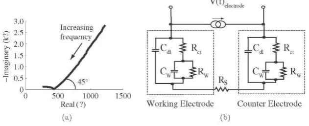
The impedance spectrum was collected to determine the surface response to a constant amplitude signal over a large range of frequencies. The cuff electrode was connected in the two-terminal configuration with the center ring as the working electrode and the short-circuited outer anodes of the cuff as the counter. This connectivity is consistent with floating psuedo-bipolar stimulation used for nerve activation. The frequency was swept over a range of 20 Hz-2 MHz at 0 V dc bias with an ac signal amplitude of 5 mV with an Agilent E4980A LCR Meter in a bicarbonate-buffered solution (mM): 112.0 NaCl, 2.0 KCl, 1.8 CaCl2-2H2O, 2.4 NaHCO3
[33]. This frequency range contained the waveform harmonics for a rectangular pulse shape with the above-mentioned parameters (subsection 2.1) as obtained using a fast Fourier transform of the recorded voltage waveform.
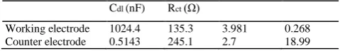
The equivalent circuit model was based on Kovacs' description of the surface [34]. The model was fitted to the impedance spectra to reflect four surface features: the double layer capacitance, the charge transfer resistance, the Warburg diffusion and the bulk resistance of the solution. The presence of two active surfaces was accounted for in the selection of equivalent electrical components. Preliminary model fitting was completed with ZViewTM software. Once a reasonable network of resistors and capacitance was identified, unweighted least-squares regression in Matlab® determined the individual component values for the impedance equation.
2.4. Waveform simulations
Current-mode waveforms with the parameters mentioned in subsection 2.1 were simulated in the PSPICE® environment. Voltage across electrodes (Velectrode(t); figure 2(b)) and the
Figure 1. Stimulus parameters of a current-mode biphasic waveform.
[image:4.595.61.281.76.178.2](1)
[image:4.595.148.464.586.715.2]capacitive subcurrents over time (/cap,„(0) were determined for one
stimulation period (e.g. 100 ms). The charge at the electrode-electrolyte interface following a biphasic waveform (2irrecoverable) was calculated according to (3). This variable reflected
the collective influence of current sourcing and sinking, as well as the natural relaxation of the interfacial processes during the interphasic delay. In theory, adjustments to the charge per phase could occur to both the cathodal and anodal phases, but in practice, we have chosen to alter the charge per phase for a single pulse (i.e. the anodal phase), which compensates for the net amount of irrecoverable charge produced during both phases of the stimulus waveform. Waveforms with equally charged phases were also compared according to their shape's charge recovery (4). Percentage charge recovery described how well the countering pulse recovered the charge injected during the first pulse:
(3)
2.5. Stimulation experiments in saline
The voltage traces collected in physiological saline were used to validate the fitted circuit by comparing the simulated system response against experimental saline recordings over a range of stimulus conditions appropriate for nerve stimulation. The system consisted of a software-controlled automated stimulation-and-recording module previously described in [35]. Waveforms were configured according to the user-specified parameters and loaded to an ac programmable current generator with a floating triax output (Keithley® 6221). The voltage across the electrodes during bipolar stimulation was recorded at 40 kHz through a data acquisition module (NI DAQPad® 6015). Recordings were collected for 2.5 and 30 s intervals with a 2 min pause to allow the electrode voltage to return toward its open circuit potential. The control software then updated the stimulus parameters and the process was repeated until responses to all waveforms were saved for post-processing analysis. The voltage offset (yoffset) was
computed as the difference between the pre-pulse potentials at the beginning and the end of a 10 Hz pulse train. The verification of the equivalent impedance model was by a statistical comparison of experimental and simulated Vdectrode(t) waveforms.
3. Results
3.1. Simulations ofthe electrode-electrolyte interface
The impedance spectrum revealed several surface processes occurring at the electrode surfaces. Diffusion and charge-transfer reactions dominated the low-frequency surface impedance as indicated by the tail at 45° in the Cole-Cole plot (figure 2(a)). At lower frequencies, reactions were able to proceed to completion with minimal diffusional loss of products, which were required for the reversible surface reactions. The dominant surface process
transitioned to the capacitive forces as the frequency was increased beyond 35 kHz. The semi-circle in the Cole-Cole plot means that reaction kinetics were the limiting factor under these conditions. The presence of a single semi-circle in a two-terminal impedance recording indicated that the relative size of the counter surface was not significantly larger than the working surface [36]. This suggested that the surface of the shorted anodes cannot be ignored when constructing the equivalent impedance model. Surface processes at the two electroactive surfaces guided the selection and arrangement of equivalent electrical components. Kovacs' description of the electrode-electrolyte interface was applied to each surface and fit to the measured impedance spectrum (R2 = 0.999) [34]. The component values listed in table 1 were implemented into a PSPICE® version of the circuit model shown in figure 2(b) for system-level simulations.
The purpose of the model in this charge-balancing study was twofold. First, it must account for the observed impedances of platinum black in the bicarbonate buffer solution. Good agreement was found between voltage waveforms in saline and simulations over waveform samples with a range of stimulus parameters (mean R2 value ± std; 0.98 ± 0.022, n = 54). Simulated waveforms were compared to measured voltage transients in figure 3. These samples were selected because they demonstrate the model's accuracy at waveform reconstruction for a lower amplitude, shorter duration waveform as well as higher amplitude, longer duration pulse.
3.2. Parameter-dependent trends
The second requirement for a model in our application was that it served as a transformation between current-mode parameters and the resulting surface processes observed during a waveform. The surface impedance was used to understand charge injection mechanisms at the electrode-electrolyte interface during a stimulus pulse. The measured waveforms revealed a notable difference between pre-pulse potentials following the initial 2.5 s of stimulus pulsing. The baseline voltage ramped-down during pulsing with cathodal-first waveforms with a dependence on the cathodal amplitude (figure 4). Simulations over a longer time course (i.e. >100 ms) did not develop the change in pre-pulse potential observed in the measured data following continuous pulsing. This limitation showed that replicating the biophysical phenomena leading to the charge build-up
Cdl (nF) Rct (Ω)
[image:5.595.312.552.91.127.2]Working electrode 1024.4 135.3 3.981 0.268 Counter electrode 0.5143 245.1 2.7 18.99 Table 1. Fitted values for the platinum black-saline interface.
Rs = 190.8 Ω.
where t is the termination of biphasic waveform with equally charged phases.
V M Woods et al
during continuous pulsing proved to be beyond the scope of this model. The model's accuracy over a single cycle allowed us to examine the subcurrent flow through the electrical components representing the different surface processes. The four capacitive features of the interface were charged during the application of the cathodal pulse. However, the fixed interphasic delay of 100 μs allowed for the fast discharge of the double-layer capacitances and further dissipation through the slower reversible processes [37, 38]. At the onset of the anodic pulse, the amount of charge required to counter the changes during the first pulse was no longer equal to the initial amount injected (i.e. Q1). Thus, application of a second pulse
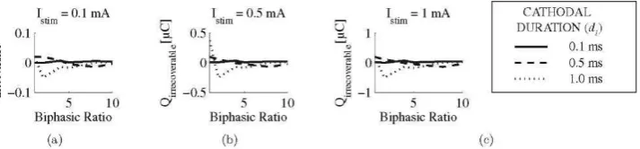
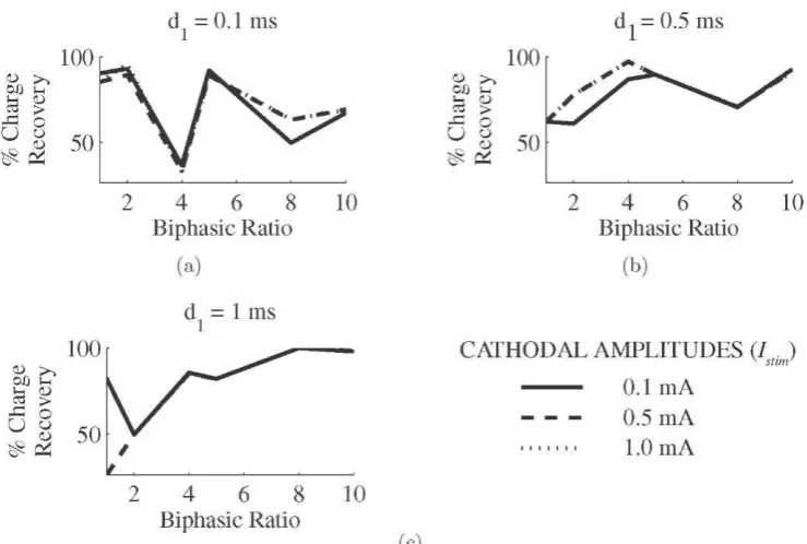
with the same charge/phase as the first caused charge to remain at the capacitors depending on the mismatching impedances of the possible current paths within the equivalent circuit. This amount of irrecoverable charge proved to depend on the cathodal amplitude (figure 5) and, as expected, mirrored the trend found in figure 4. The charge recovery findings in figure 6 showed that recovery was not dependent on the cathodal amplitude, but was loosely correlated to the pulse duration and biphasic ratio. Longer pulse durations with larger biphasic ratios had the best recovery at 98% (figure 6(c)). Improved recovery with an increased biphasic ratio was also noted for the pulse duration of 0.5 ms (figure 6(b)). However, the opposite
trend was observed with the shortest pulse width (d1 = 0.1 ms, figure
6(a)). Its highest recovery rates were at
90% for BR = 1 and 92% for BR = 5 with Istim = 0.1 mA.
3.3. Charge-balancing waveforms
[image:6.595.150.453.74.207.2]The circuit model served as a tool for mapping surface conditions to features of the input signals assuming a static nonlinear description of the interface. This association builds the framework for successful charge balancing based on safe and reversible interfacial processes. The most accurate integration of electrochemical insights into the waveform design for preempting charge accumulation would require predictions based on an equivalent model with adapting component values. However, derivation of such a model is out of the scope of this analysis. Rather, we will accept the limitations of the static model and assume a constant description of the metal-saline interface for the purpose of waveform design.
[image:6.595.115.487.253.336.2]Figure 3. Comparison of measured and simulated voltage waveforms over the entire range of stimulus parameters used in this study. Traces here show (a) 100 μΑ, 100 ^sand BR =1(R2 = 0.986); (b) 1 mA, 1 ms and BR = 10 (R2 = 0.971).
Figure 4. The change in pre-pulse potentials for the cathodal pulse durations of 100 μs, 500 μs and 1 ms at amplitudes of (a) 100 μΑ; (b) 500 μΑ and (c) 1 mA. Differences were calculated after 2.5 s of 10 Hz pulsing.
[image:6.595.126.483.379.462.2]We worked under the assumption that changes in the pre-pulse potentials during a pulse train were created by the culmination of charge losses due to the individual pulses. Equally charged biphasic waveforms were simulated and the charge remaining in the system was computed according to (3). This amount was then used to construct new waveforms by correcting for the charge losses during a single stimulation cycle. The goal being that a biphasic waveform with the proper charge compensation would produce a pulse train with minimal change in pre-pulse potentials over an extended recording (i.e. Voffset -> 0 V). The excess interfacial charge was
eliminated by an appropriate adjustment to the anodal charge amount for the development of biphasic waveforms with unequally charged phases. The duration of the anodal pulse was changed according to the predicted polarity of the simulated Qirrecoverable. We
call this method of waveform design 'the offset prediction technique'. Waveforms were constructed in a manner similar to the equally charged waveforms in which the user specified the cathodal amplitude, duration and the biphasic amplitude ratio. The anodic duration was calculated using the values in figure 5 according to
(4)
where
An experimental comparison of conventional equally charged stimulus pulses with unequally charged waveforms constructed according to the offset prediction technique is shown in figure 7. Stimulation in a saline bath with the equally charged biphasic waveforms resulted in a significant change in pre-pulse potentials, as indicated by the net voltage offset of 530 mV over a 30 s recording (figure 7(a)). However, a waveform with unequally charged phases,
but with the same cathodal parameters as the waveform in figure
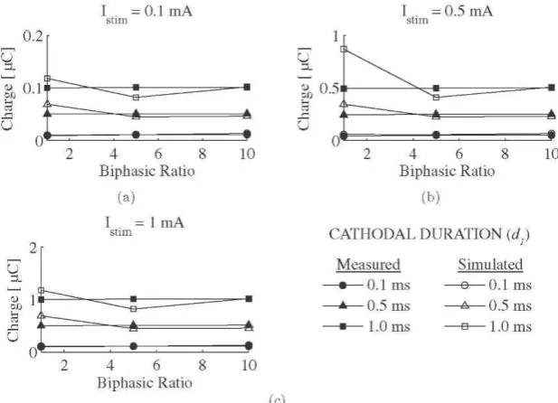
7(a), effectively compensated for its charge residues (figure 7(b)). Both waveforms in figures 7(a) and (b) demonstrated interference at 0.7-1 Hz. As this was present in both measurements, it has the same effect on the dc offset (or the remaining charge) and therefore does not affect the effectiveness of the method. Waveforms constructed with unequally charge phases had a 92% reduction ( n = 20) in the difference between pre-pulse potentials following a 30 s, 10 Hz pulse train compared to waveforms with equally charged phases. The experimentally determined Q2values showed strong agreement
(R2 = 0.95, n = 27) with the theoretically calculated Q2values from
the equivalent impedance model over a range of stimulus parameters (figure 8). Simulated results better matched the measured results for shorter pulse durations and larger biphasic ratios.
4. Discussion
[image:7.595.115.485.73.322.2]Cathodal-first biphasic waveforms were defined according to their amplitude, duration and biphasic ratio. A notable rise in the difference between pre-pulse potentials following a period of continuous pulsing occurred with increasing the cathodal amplitude (figure 4). This is expected because as the potential moves away from its open circuit potential, charge injection occurs through irreversible processes [39]. Without the ability to directly measure the charge lost at the interface, we used the change in pre-pulse potentials following a biphasic waveform
V M Woods et al
[image:8.595.139.456.78.334.2]as an indicator of the charge in the system [20]. The metal-saline interface was measured and modeled with an equivalent electrical network reflecting the electrochemical mechanisms of charge injection (figures 2(a) and (b)). Parameter selection for waveforms with equally charged phases was optimized for minimal charge accumulation by simulating the voltage across the electrode during a biphasic waveform. Similar to the parameter-dependent trend in
[image:8.595.145.457.82.198.2]figure 4, we found that simulated charge amounts were also correlated with the cathodal amplitude (figure 5). Interestingly though, biphasic waveforms with increased pulse duration and increased biphasic ratio had lower amounts of residual charge per amount of charge injected (figure 6). Single pulse analysis reported elsewhere showed that longer cathodal pulse did
Figure 7. Stimulation tests in a bicarbonate buffer solution comparing the voltage across the electrodes for a biphasic waveform with equally charged phases (a) and one with unequally charged phases determined according to the offset prediction technique (b). Both waveforms had a cathodal amplitude of 1 mA with a pulse duration of 100 μs and BR = 10 (frequency = 10 Hz).
[image:8.595.147.456.390.613.2]not necessarily cause less surface damage [37, 38]. Rather, longer pulse widths (50-1000 μs) have a slight increase in unrecoverable charge with higher charge densities for pulse-clamped platinum electrodes [37, 38]. This leads us to believe that the improved charge recovery is due to the effects of the counterbalancing pulse. The biphasic ratio was included in this analysis because it allows us to quantify how effective the shape of the counterbalancing pulse is at correcting the effects of the cathodal pulse. A larger biphasic ratio means that the amplitude of the second pulse is lower and the duration is longer. In effect, this would pull the voltage generated by the cathodal pulse toward the range closer to its open circuit potential. The larger the biphasic ratio, the less likely the potential will overshoot its open circuit value. Electrode corrosion is minimized the longer this lower amplitude countering pulse is applied because faradaic reactions associated with overshooting the open circuit potential are reduced. However, as the potential is returning from its cathodal peak toward its open circuit value, additional faradaic reactions can occur. These can act to reverse those driven during the up-sweep, if given sufficient time at the required reaction potential and if the initial products have remained close to the electrode surface. Otherwise, irreversible reactions can occur and lead to electrode damage. In general, further recruitment of faradaic reactions, reversible or irreversible, during the downward sweep of a biphasic voltage waveform is unavoidable. While we have presented evidence that the careful design of biphasic waveforms can minimize the difference between the pre-pulse pulse potentials following extended pulsing, there is an intrinsic cost associated with this method.
Waveforms with unequally charged phases assume that there is a finite amount of charge which can be added to an individual waveform such that it will produce a charge-balanced pulse train. During the application of the first pulse, the potential at the central (cathodal) surface drives electrochemical reactions that consume charge through platinum reduction, H-plating and H2 evolution [8].
The anodal surfaces experience an electrochemical situation at the opposite end of the voltage range, where charge injection occurs through platinum oxidation and O2 evolution [8]. During the second
phase of the applied current-mode signal, the biphasic ratio determines the extent of the pulse's countering processes. The cathode will experience anodic reactions and the anode will experience cathodic reactions. It follows that, with phasic imbalances, each surface will experience either more or less of the countering reactions depending on the polarity of the predicted compensation. McHardy et al [30] reasoned that these charge offsets increase the availability of products for reaction reversal when they would have otherwise been lost to diffusion processes during a waveform with equally charged phases. They presented the concept of 'cathodal protection' from a 'sacrificial anode'. Here, the countering reactions on the anode allow for a slight charge build-up on its surface in order to prevent damage at the cathodal surface. Within our measurement system, we analyzed the differential voltage across the electrodes because it was more appropriate for our purposes. The effects at an individual surface arecompounded into an indicatorofsystem stability in a manner well suited for monitoring during clinical implementation. We investigated the effect of small changes in the system on the system's behavior as a whole, making it difficult to identify single surface subtleties. As a result, these slight surface imbalances created a minimal difference in pre-pulse
potential following a pulse train. Within this situation, the benefit of biphasic waveforms with unequally charged phases arises from its capability to correct the damaging trends observed with conventional waveforms.
An equivalent model provides the opportunity to describe and predict the associated impedance states under a variety of stimulus conditions relevant to nerve activation. Its predictions are based only on the electrical approximations of the electrochemical mechanisms of charge injection. The inherent limitations of such a strategy explain why our simulations are accurate over a single stimulation cycle rather than a continuous pulse train [8, 22]. It must be noted that surface conditions encountered during a single pulse are much different than those occurring during a steady-state pulse train. However, the value of integrating single-pulse predictions based on the static model of the interface into a waveform design for continuous pulsing can be improved to better represent pulse-train conditions. If the surface impedance were periodically resampled and the model's RC components were updated on a much shorter time scale than 30 s, then the single-pulse simulations could better reflect the potentials driving the interfacial processes during a pulse train. The method of waveform design with unequally charged phases along with insights from interfacial simulations highlight that irrecoverable charge can be appropriately accounted for by exploiting the natural interfacial features of charge injection without the addition of advanced hardware or controls.
Acknowledgments
The authors would like to thank Dr Martin Schiittler of the Institute for Biomedical Microtechnology (IMTEK, Germany) for fabricating the electrodes used in this study. This work was also supported by the Whitaker Foundation (USA) and Esmee Fairbairn Foundation (UK).
References Q2
[1] Naples C G, Mortimer J T and Yuen T G H 1990 Overview of peripheral nerve electrode design and implantation Neural Prostheses: Fundamental Studies
ed W F Agnew and D B McCreery (Englewood Cliffs, NJ: Prentice-Hall) pp 108-45
[2] Grill W M and Mortimer J T 1995 Stimulus waveforms for selective neural stimulation IEEE Eng. Med. Biol. Mag.
14 375-85
[3] Jarvis J C and Salmons S 2001 The application and technology of implantable neuromuscular stimulators: an introduction and overview Med. Eng. Phys.
23 3-7
[4] Bhadra N, Kilgore K L and Peckham P H 2001 Implanted
stimulators for restoration of function in spinal cord injury Med. Eng. Phys. 23
19-28 [5] Rijkhoff N J M, Wijkstra H, van Kerrebroeck P E V
V M Woods et al
intraoperative testing in humans during implantation of a Finetech-Brindley system World J. Urol. 16 337-41 [6] Robblee L S and Rose T L 1990 Electrochemical guidelines for selection of protocols and electrode materials for neural stimulation Neural Prostheses: Fundamental Studies ed W F Agnew and D B McCreery (Englewood Cliffs, NJ:
Prentice-Hall) pp 25-66
[7] Merrill D R, Bikson M and Jefferys J G R 2005 Electrical stimulation of excitable tissue: design of efficacious and safe protocols J. Neurosci. Methods141 171-98
[8] Brummer S B and Turner M J 1977 Electrochemical
considerations for safe electrical stimulation of nervous system with platinum electrodes IEEE Trans. Biomed. Eng.
24 59-63
[9] Brummer S B, Robblee L S and Hambrecht F T 1983 Criteria for selecting electrodes for electrical stimulation: theoretical and practical considerations
Ann. New York Acad. Sci. 405 159-71 [10] Stieglitz T 2004 Electrode materials for recording and stimulation Neuroprosthetics Theory and Practice
ed K W Horch and G S Dhillon (Singapore: World Scientific) pp 475-516
[11] Donaldson N and Donaldson P E K 1986 When are actively
balanced biphasic ('Lilly') stimulating pulses necessary in a neurological prosthesis? I. Historical background; Pt resting potential; Q studies Med. Biol. Eng. Comput. 24 41-9
[12] Schuttler M, Andrews B J and Donaldson N 2004 Blocking of peripheral nerve conduction using ac signals: which frequency is best? Proc. 9th Annual Conf. of the Int. Functional Electrical Stimulation Society pp 324-6
[13] Kilgore K L and Bhadra N 2004 Nerve conduction block utilising high-frequency alternating current Med. Biol. Eng. Comput. 42 394-406
[14] Cogan S F 2008 Neural stimulation and recording electrodes
Annu. Rev. Biomed. Eng. 10 275-309 [15] Lilly J C, Hughes J R, Alvord E C Jr and Galkin T W 1955
Brief, noninjurious electric waveform for stimulation of the brain Science121 468-9 [16] Rubinstein J T, Miller C A, Mino H and Abbas P J 2001
Analysis of monophasic and biphasic electrical stimulation of nerve IEEE Trans. Biomed. Eng. 48 1065-70
[17] Rose T L and Robblee L S 1990 Electrical stimulation with Pt
electrodes: VIII. Electrochemically safe charge injection limits with 0.2 ms pulses IEEE Trans. Biomed. Eng. 37 1118-20
[18] Hibbert D B, Weitzner K and Carter P 2001 Voltammetry of platinum in artificial perilymph solution J. Electrochem. Soc. 148
E1-7
[19] Hudak E M, Mortimer J T and Martin H B 2010 Platinum for neural stimulation: voltammetry considerations J. Neural
Eng. 7 026005
[20] Mailley S, Hyland M, Mailley P, McLaughlin J A
and McAdams E T 2004 Thin film platinum cuff electrodes for neurostimulation: in vitro approach of safe neurostimulation parameters Bioelectrochemistry 63 359-64
[21] Weinman J and Mahler J 1964 An analysis of electrical properties of metal electrodes Med. Electron. Biol. Eng.
2 299-310
[22] Weinman J 1965 Biphasic stimulation and electrical properties of metal electrodes J. Appl. Physiol. 20 787-90
[23] Dymond A M 1976 Characteristics of the metal-tissue interface of stimulation electrodes IEEE Trans. Biomed. Eng. 23 274-80
[24] Smith B, Tang Z, Johnson M W, Pourmehdi S, Gazdik M M, Buckett J R and Peckham P H 1998 An externally powered, multichannel, implantable stimulator-telemeter for control of paralyzed muscle
IEEE Trans. Biomed. Eng.
45 463-75
[25] Loeb G E, Zamin C J, Schulman J H and Troyk P R 1991 Injectable microstimulator for functional electrical stimulation Med. Biol. Eng. Comput. 29 NS13-9
[26] Sit J J and Sarpeshkar R 2007 A low-power
blocking-capacitor-free charge-balanced electrode stimulator chip with less than 6 nA dc error for 1-mA full-scale stimulation IEEE Trans. Biomed. Circuits Syst. 1 172-183
[27] Schuttler M, Franke M, Krueger T B and Stieglitz T 2008 A voltage-controlled current source with regulated electrode bias-voltage for safe neural stimulation J. Neurosci.
Methods171 248-52
[28] Ortmanns M, Unger N, Rocke A, Gehrke M and Tietdke H J 2007 A 0.1 mm, digitally programmable nerve stimulation pad cell with high-voltage capability for a retinal implant Proc. IEEE Int. Solid-State Circuits pp 89-98
[29] Sooksood K, Stieglitz T and Ortmanns M 2009 An
experimental study on passive charge balancing Adv. Radio Sci. 7 197-200
[30] McHardy J, Geller D and Brummer S B 1977 An approach to corrosion control during electrical stimulation Ann. Biomed. Eng. 5 144-9
[31] Scheiner A, Mortimer J T and Roessmann U 1990 Imbalanced biphasic electrical stimulation: muscle tissue damage Ann. Biomed. Eng. 18
407-25
[32] Honert C van den and Mortimer J T 1979 The response of the myelinated nerve fiber to short duration biphasic stimulating currents Ann. Biomed. Eng. 7 117
[33] Katsuki R, Fujita T, Koga A, Liu T, Nakatsuka T, Nakashima M and Kumamoto E 2006 Tramadol, but not its major metabolite (mono-o-demethyl tramadol) depresses compound action potentials in frog sciatic nerves Br. J. Pharmacol. 149 319-27
[34] Kovacs G T A 1994 Introduction to the theory, design and modeling of thin-film microelectrodes for neural interfaces
Enabling Technologies for Cultured Neural Networks ed D A Stenger and T McKenna (New York: Academic) pp 121-65 [35] Woods V M, Triantis I F and Toumazou C 2008 A
reconfigurable and automated system for the study of stimulus waveform parameters Proc. 13th Annual Conf. of the Int. Functional Electrical Stimulation Society
pp 288-90
[36] Karunathilakaa S A G R, Hampsona N Aand Leekb R 1981
The impedance of two-terminal electrochemical cells Surf. Technol. 13
339-18 [37] Mortimer J, Bonner M and Daroux M 1990 Effect of pulsewidth and delay on stimulating electrode charge injection
in-vitro Proc. 12th Annual Conf. ofthe IEEE Engineering in Medicine and Biology Society vol 12, pp 1482-3
[38] Bonner M 1991 The pulse clamp method for analyzing neural stimulating electrodes PhD Thesis Case Western Reserve University, Cleveland, OH
[39] Brummer S B and Turner M J 1977 Electrical stimulation with Pt electrodes: II. Estimation of maximum surface redox (theoretical non-gassing) limits IEEE Trans. Biomed. Eng.